

Elektor MultiCalculator Kit
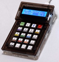
More than just a calculator. Measure light, temperature, differential temperature, decode NEC IR remote control codes and perform other tasks. 22 Modes of operation.
Board and software developed by Ruud van der Meer (RM electronics)
Schematic
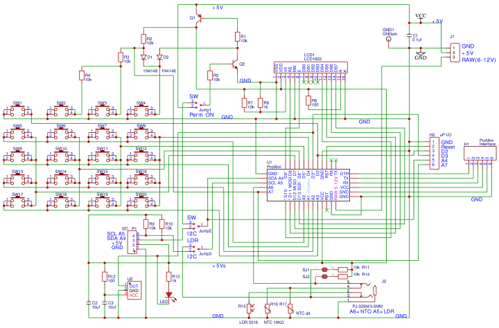
Fig.1. Schematic of the MultiCalculator
The MultiCalculator is built around a Pro Mini and is programmable, even after the construction is finished, through a 6way female header at the back. The software is bilingual, the menu language can be Dutch or English. Power supply voltage is 5 V, supplied via a USB-C plug at the back. Current is around 30mA. The design can also be used for other functions (using custom software) and can be programmed via the Arduino IDE. The serial ports have been kept free for monitoring or other functions. There are extra connections on the PCB, e.g.: GND, Reset, D2, D3, A4, A7 (connector H2, not used/fitted in the MultiCalculator). An I2C connection is available (connector P1, also not used/fitted in the MultiCalculator). To use I2C however, the required soldering bridges must be soldered then. Disabling via software is not possible with I2C enabled: dual-solder bridge 2 (I2C/Sw) next to R6 for SDA (A4) and dual-solder bridge 3 (I2C/LDR) next to R9 for SCL (A5). Only one solder bridge must be soldered of each dual-solder bridge on the PCB! The Pro Mini module only has so many I/O ports available. I/O ports A5 and A6 are available on the 3.5mm jack J2, connected by a track in solder bridges SJ1 and SJ2 to pullup resistors of 10kΩ (R11 and R14 respectively). These I/O ports can be used for temperature measurements or other applications (depending on the software). To sever the connections to these pull-up resistors cut the small track between the pads of SJ1 and SJ2. If the connection needs to be restored make a solder bridge between the adjacent pads. The LDR and NTC sensors are always connected to ground, and A5 (LDR/NTC) and A6 (NTC) respectively. On the PCB an NTC can be placed in two locations, R16 or R17. The two connections of R16 and R17 are connected in parallel so only 1 NTC must be mounted! Use R16 and leave R17 unmounted. R16 is farthest away from de module (should it get warm).
An analog input port is used to read switches SW2, SW3, SW4 by changing resistance through the selection of taps of series connection R2 (via D1), R3 and R4. SW2, SW3 are only used to a limited extent in the software. SW5 to SW20 are connected in a matrix. SW1 is used to change the mode of the MultiCalculator and is connected to a separate I/O port (D2). By pressing the MODE switch, the next mode of operation can be chosen. By pressing the mode button longer, the previous mode is chosen. In version 1.1 of the software 22 modes of operation are available.
SW4 is used to turn the MultiCalculator ON or OFF by software, depending on dual-solder bridge 1 next to R3 (On/Sw). If the solder bridge ON is made the MultiCalculator is always powered as soon as 5 V is supplied through the USB-C connector. If solder bridge Sw is made pressing SW4 will turn PNP transistor Q1 ON. It will pull R1 to ground via D2, the power supply is connected to the circuit and the module starts. SW4 must be pushed long enough for the module to make I/O port A4 high. Q1 is turned on through R5 and NPN transistor Q2. If A4 is low the MultiCalculator is switched OFF. The calculator can also be supplied with a voltage of 6-12 volt through the RAW connection on the PCB (J1). A small 5 V voltage regulator is part of the power supply circuit of the Pro Mini module. Switching ON is done by pressing the ON/AC button SW4 for a few seconds until text appears on the display. Switching OFF is done by pressing the ON button for more than 4 seconds. When the key is released, the MultiCalculator is turned off.
Originally the author used a SS8550 for PNP transistor Q1 and a 2SC9013 for NPN transistor Q2 as is indicated on the PCB. Due to availability these were replaced by types KSA708YBU and 2N3904. The exact type is not that critical but if a replacement is necessary pay attention to the pin order of the transistors. The types mentioned here have a different pin order than for instance types BC547 or BC337!
Programming the Arduino Pro Mini can be done via a USB-C to TTL converter (part of the kit). Make sure the jumper on the programming adapter is placed in the 5V position.
The custom enclosure is made of a total of 11 separate transparent acrylic panels. The top panels are dark brown transparent acrylic panels, the rest are clear. A USB-C connector is used connect a 5 V power supply.
Differential temperature measurement.
One mode of operation is not fully clarified in the user manual. To use the differential temperature measurement mode the cable of both waterproof sensors in the kit must be soldered to 3.5 mm plug (also in the kit). The plug can then be inserted in the 3.5 mm jack in the back of the MultiCalculator.
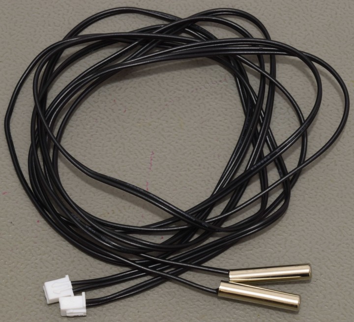
Fig. 2. The waterproof sensors as supplied in the kit
Cut off the connectors from the cables of the waterproof sensors. Each sensor should be soldered to the GND terminal of the 3.5 mm plug and the other wire of each sensor to one of the other contacts of the plug. Best is to cut the ground wires a few mm shorter so the other two are a bit longer and can each be soldered to one of the other 2 contacts of the 3.5 mm plug without having to bend the wires. The plug in the kit can be different than the one shown in the photo. Before soldering don’t forget to place the shell of the 3.5 mm plug over the cables of the sensors first. The plug in the kit can be different from the one shown in the photo.
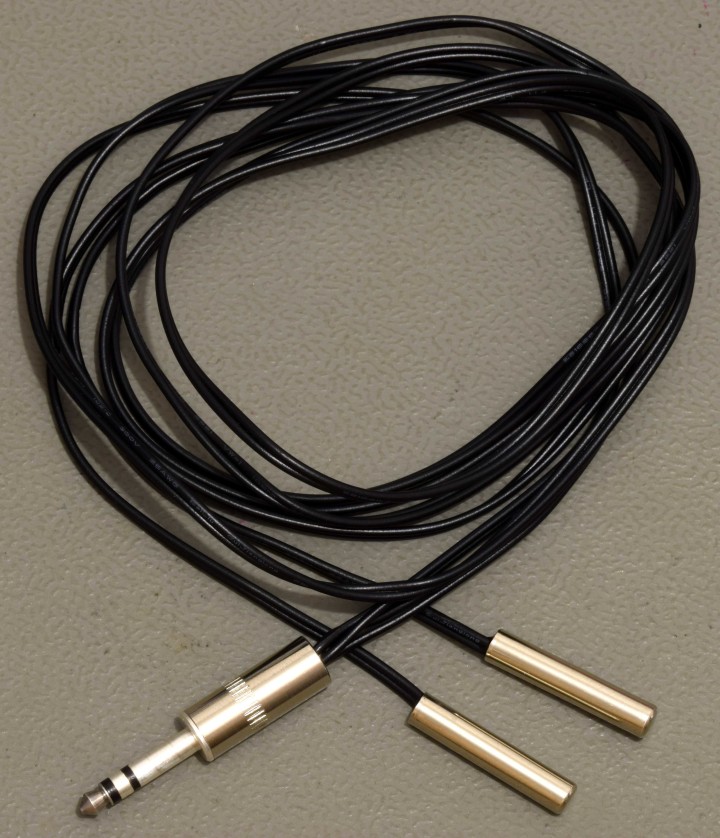
Fig. 3. 2 Waterproof sensors connected to the 3.5 mm plug
Measurements using the waterproof sensors are a bit slow because the NTC is place in a epoxy filled 5 x 25 mm round metal tube. Operating temperature of these sensors is -40 to +85 °C.
Details on construction and a description of all modes of operation can be found in the ‘Construction and User Manual’ (can be downloaded at www.elektor.com). Following photo’s give an impression
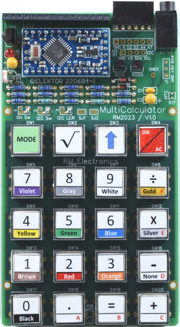
Fig. 4. All parts except the LCD fitted.
A 18.5 mm long pin header must be soldered to the display under an angle. Nothing is bent!
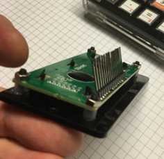
Fig. 5. The header soldered to the display
The USB-C connector must be mounted in the back panel before its wires can be soldered to the PCB.
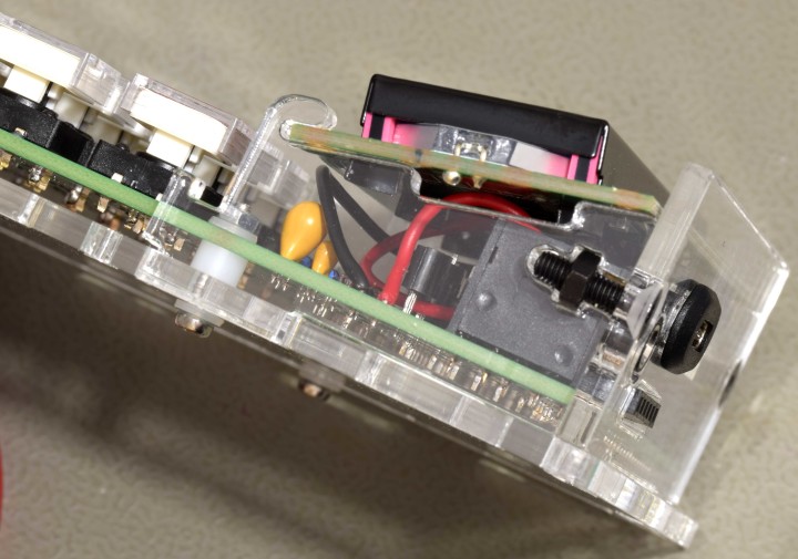
Fig. 6. Detail of back panel, display support with screws and M2 screw of the PCB.
Fig.7. Back of the finished MultiCalculator.
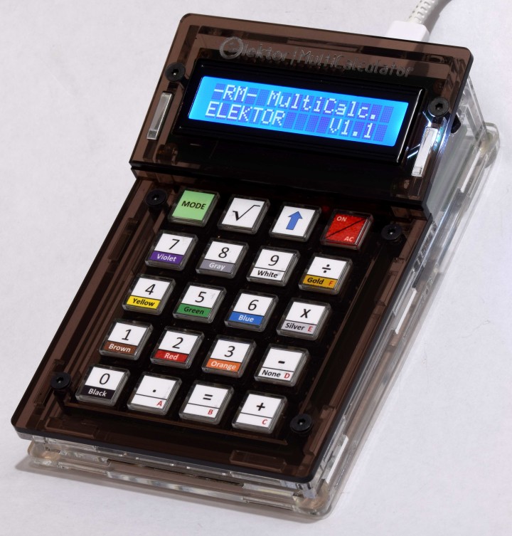
Fig. 8 The MultiCalculator is ready.
Specifications/properties
Power supply voltage 5V (USB-C)
Power supply current ≈ 28…32 mA
ProMini microcontroller module (ATmega328/5V/16MHz)
Programmable by the Arduino IDE (6way female pin header)
2x16 alpha-numerical LCD (LCD 1602, display color blue, white text)
20 labeled pushbuttons
3.5 mm jack to connect external sensors
Operating temperature of waterproof sensors -40 to +85 °C.
22 Menus (software version 1.1)
Functions:
Modes of operation (software v1.1)
1 – Calculator
2 – 4 Ring Resistor Code
3 – 5 Ring Resistor Code
4 – Decimal to Hexadecimal and Character (ASCII) conversion
5 – Hexadecimal to Decimal and Character (ASCII) conversion
6 – Decimal to Binary and Character (ASCII) conversion
7 – Binary to Decimal and Hexadecimal conversion
8 – Hz, nF, reactance Xc calculation
9 – Hz, µH, reactance Xl calculation
10 – Resistance calculation of two resistors connected in parallel
11 – Resistance calculation of two resistors connected in series
12 – Calculation unknown parallel resistor
13 – Temperature measurement
14 – Differential temperature measurement T1&T2 and Delta (δ)
15 – Light measurement
16 – Stopwatch with lap time function
17 – Item counter
18 – Display IR NEC code from a remote control
19 – AWG conversion (American Wire Gauge)
20 – Rolling Dice
21 – Personalize startup message
22 – Temperature calibration
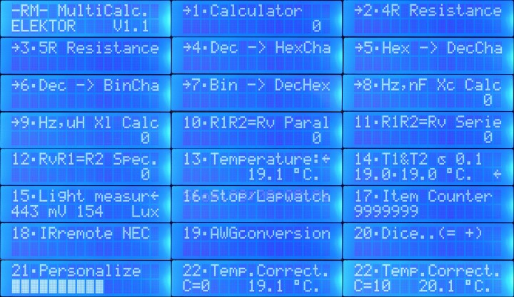
Fig. 9. Startup message and all 22 modes (message when selected) of the MultiCalculator.
Bill of Materials, contents of the kit
Resistor
R1,R2,R3,R4,R5,R7,R9,R10,R11,R14 = 10 kΩ, 167 mW, 1 %., body 1.9 x 3.4 mm
R6,R12 = 100 Ω, 250 mW, 1%, body 2 x 3.5 mm
R8,R13 = 1 kΩ, 167 mW, 1 %, body 1.9 x 3.4 mm
R15 = LDR GL5516, 5.4 x 4.4 mm, lead spacing 3.4 mm
R16 = NTC 10 kΩ, type 3950, 5% 10 kΩ
R17 = not needed
Capacitor
C1 = 100 nF, 50 V, 10 %, X7R, lead spacing 2.5 mm
C2,C3 = 10 µF, 25 V, 10 %, tantalum, lead spacing 2.5 mm
Semiconductor
D1,D2 = 1N4148, DO-35
LED = 3 mm (T1) LED, red
Q1 = KSA708YBU, TO-92
Q2 = 2N3904, TO-92
U1 = Mini Pro (ATmega328P, 5 V, 16 MHz)
U2 = TSOP14438
LCD1 = LCD module 16 x 2, Alphanumeric, 36 x 80 mm
Other
J1 = USB-C socket, chassis mounted, wired (5 V power supply only), 9 x 16 mm
J2 = 3.5 mm headphone jack, PCB mount PJ-325M (5 pins connections, 2 switched contacts)
H1 = 6way female header, right angle, pitch 2.54 mm
H2 = not needed
P1 = not needed
SW1-SW20 = 12x12x7.3mm Tactile Switches
SW1-SW20 = Keytop + clear cap for switches (cap is 11.8 mm square)
LCD1 = 16way male pin header, height 18.54 mm, pitch 2.54 mm, vertical
LCD1 = 16way socket, pitch 2.54 mm, vertical
FT232 Pro Mini USB-C TTL Adaptor (with 3 pin 3.3V/5V selection)
U1 = 12way pin header, vertical, pitch 2.54 mm (for Mini Pro)
2 x NTC 10 kΩ, Waterproof Temperature Sensor type 3950 10K, 1 m cable
3.5 mm plug
USB-A to USB-C cable, 1 m
Enclosure
4 x screw, M2, 12 mm, steel
4 x spacer sleeve, cylindrical, L: 3mm, Øout: 5mm, polyamide
4 x nut, M2, steel
8 x washer, M2, D=5mm, H=0.3mm, polyamide
4 x screw, M3, 6 mm, steel
4 x washer, M3, D=7mm, H=0.5mm, polyamide
4 x standoff, M3, Female-Female, Øout: 6mm L:8 mm, polyamide
4 x screw, M3, 10 mm, Head: countersunk, hex (Allen) key, HEX 2mm, steel
4 x screw, M3, 12 mm, Head: countersunk, hex (Allen) key, HEX 2mm, steel
4 x nut, M3, Plating: black finish, H: 2.4mm, steel
4 x self-adhesive foot; H: 3.8mm, transparent, polyurethane
6 panels made of 3 mm extruded acrylic transparent/clear sheet:
back panel, front panel, bottom panel, 2 side panels, U-shaped keyboard support panel
2 display support panels made of 5 mm extruded acrylic transparent/clear sheet
3 panels made of 3 mm cast acrylic umbra transparent sheet (dark brown):
display bezel, small support for display bezel, keyboard panel
Misc.
PCB 220684-1 v1.0
PCB
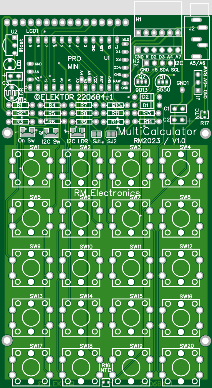
Fig. 10. Top overlay of PCB 220684-1 v1.0 of the MultiCalculator
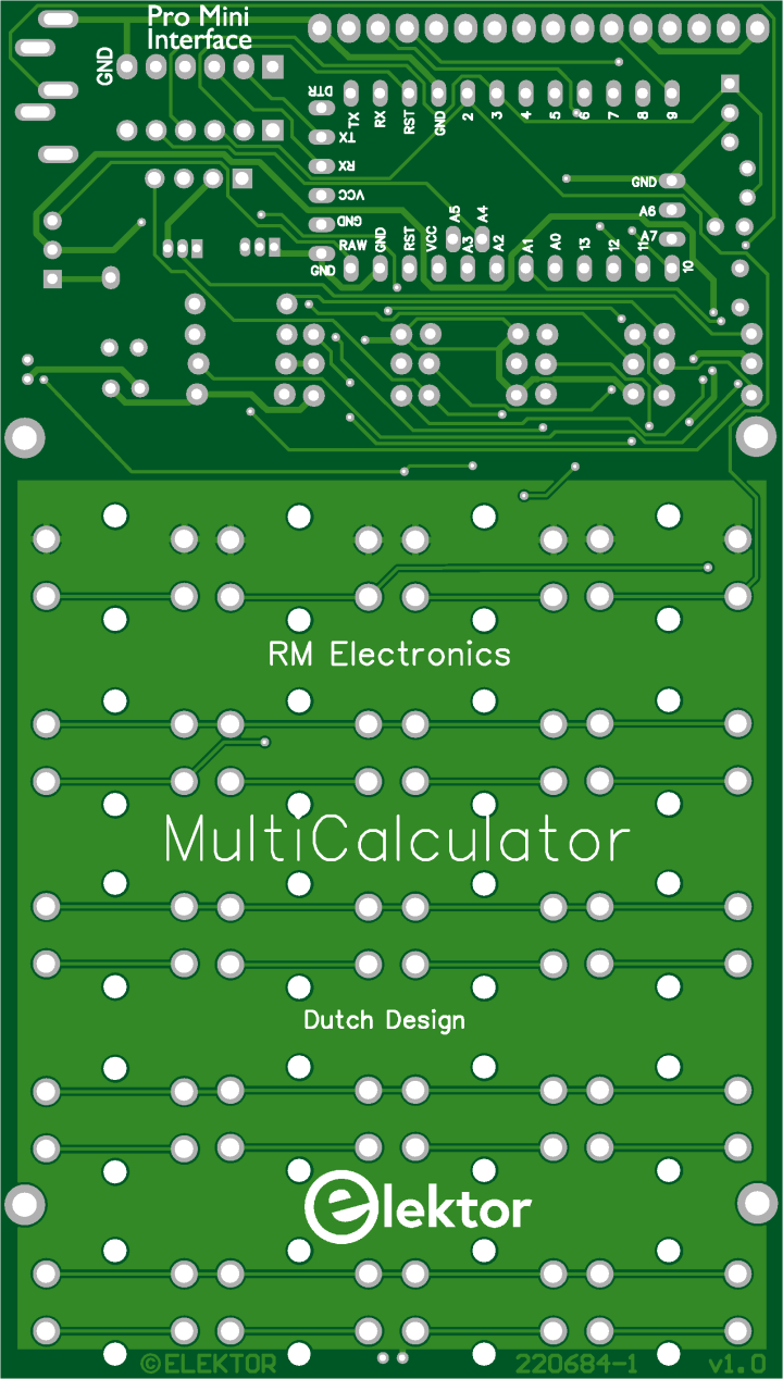 Fig. 11. Bottom overlay of PCB 220684-1 v1.0 of the MultiCalculator
Schematic
Fig.1. Schematic of the MultiCalculator
The MultiCalculator is built around a Pro Mini and is programmable, even after the construction is finished, through a 6way female header at the back. The software is bilingual, the menu language can be Dutch or English. Power supply voltage is 5 V, supplied via a USB-C plug at the back. Current is around 30mA. The design can also be used for other functions (using custom software) and can be programmed via the Arduino IDE. The serial ports have been kept free for monitoring or other functions. There are extra connections on the PCB, e.g.: GND, Reset, D2, D3, A4, A7 (connector H2, not used/fitted in the MultiCalculator). An I2C connection is available (connector P1, also not used/fitted in the MultiCalculator). To use I2C however, the required soldering bridges must be soldered then. Disabling via software is not possible with I2C enabled: dual-solder bridge 2 (I2C/Sw) next to R6 for SDA (A4) and dual-solder bridge 3 (I2C/LDR) next to R9 for SCL (A5). Only one solder bridge must be soldered of each dual-solder bridge on the PCB! The Pro Mini module only has so many I/O ports available. I/O ports A5 and A6 are available on the 3.5mm jack J2, connected by a track in solder bridges SJ1 and SJ2 to pullup resistors of 10kΩ (R11 and R14 respectively). These I/O ports can be used for temperature measurements or other applications (depending on the software). To sever the connections to these pull-up resistors cut the small track between the pads of SJ1 and SJ2. If the connection needs to be restored make a solder bridge between the adjacent pads. The LDR and NTC sensors are always connected to ground, and A5 (LDR/NTC) and A6 (NTC) respectively. On the PCB an NTC can be placed in two locations, R16 or R17. The two connections of R16 and R17 are connected in parallel so only 1 NTC must be mounted! Use R16 and leave R17 unmounted. R16 is farthest away from de module (should it get warm).
An analog input port is used to read switches SW2, SW3, SW4 by changing resistance through the selection of taps of series connection R2 (via D1), R3 and R4. SW2, SW3 are only used to a limited extent in the software. SW5 to SW20 are connected in a matrix. SW1 is used to change the mode of the MultiCalculator and is connected to a separate I/O port (D2). By pressing the MODE switch, the next mode of operation can be chosen. By pressing the mode button longer, the previous mode is chosen. In version 1.1 of the software 22 modes of operation are available.
SW4 is used to turn the MultiCalculator ON or OFF by software, depending on dual-solder bridge 1 next to R3 (On/Sw). If the solder bridge ON is made the MultiCalculator is always powered as soon as 5 V is supplied through the USB-C connector. If solder bridge Sw is made pressing SW4 will turn PNP transistor Q1 ON. It will pull R1 to ground via D2, the power supply is connected to the circuit and the module starts. SW4 must be pushed long enough for the module to make I/O port A4 high. Q1 is turned on through R5 and NPN transistor Q2. If A4 is low the MultiCalculator is switched OFF. The calculator can also be supplied with a voltage of 6-12 volt through the RAW connection on the PCB (J1). A small 5 V voltage regulator is part of the power supply circuit of the Pro Mini module. Switching ON is done by pressing the ON/AC button SW4 for a few seconds until text appears on the display. Switching OFF is done by pressing the ON button for more than 4 seconds. When the key is released, the MultiCalculator is turned off.
Originally the author used a SS8550 for PNP transistor Q1 and a 2SC9013 for NPN transistor Q2 as is indicated on the PCB. Due to availability these were replaced by types KSA708YBU and 2N3904. The exact type is not that critical but if a replacement is necessary pay attention to the pin order of the transistors. The types mentioned here have a different pin order than for instance types BC547 or BC337!
Programming the Arduino Pro Mini can be done via a USB-C to TTL converter (part of the kit). Make sure the jumper on the programming adapter is placed in the 5V position.
The custom enclosure is made of a total of 11 separate transparent acrylic panels. The top panels are dark brown transparent acrylic panels, the rest are clear. A USB-C connector is used connect a 5 V power supply.
Differential temperature measurement.
One mode of operation is not fully clarified in the user manual. To use the differential temperature measurement mode the cable of both waterproof sensors in the kit must be soldered to 3.5 mm plug (also in the kit). The plug can then be inserted in the 3.5 mm jack in the back of the MultiCalculator.
Fig. 2. The waterproof sensors as supplied in the kit
Cut off the connectors from the cables of the waterproof sensors. Each sensor should be soldered to the GND terminal of the 3.5 mm plug and the other wire of each sensor to one of the other contacts of the plug. Best is to cut the ground wires a few mm shorter so the other two are a bit longer and can each be soldered to one of the other 2 contacts of the 3.5 mm plug without having to bend the wires. The plug in the kit can be different than the one shown in the photo. Before soldering don’t forget to place the shell of the 3.5 mm plug over the cables of the sensors first. The plug in the kit can be different from the one shown in the photo.
Fig. 3. 2 Waterproof sensors connected to the 3.5 mm plug
Measurements using the waterproof sensors are a bit slow because the NTC is place in a epoxy filled 5 x 25 mm round metal tube. Operating temperature of these sensors is -40 to +85 °C.
Details on construction and a description of all modes of operation can be found in the ‘Construction and User Manual’ (can be downloaded at www.elektor.com). Following photo’s give an impression
Fig. 4. All parts except the LCD fitted.
A 18.5 mm long pin header must be soldered to the display under an angle. Nothing is bent!
Fig. 5. The header soldered to the display
The USB-C connector must be mounted in the back panel before its wires can be soldered to the PCB.
Fig. 6. Detail of back panel, display support with screws and M2 screw of the PCB.
Fig.7. Back of the finished MultiCalculator.
Fig. 8 The MultiCalculator is ready.
Specifications/properties
Power supply voltage 5V (USB-C)
Power supply current ≈ 28…32 mA
ProMini microcontroller module (ATmega328/5V/16MHz)
Programmable by the Arduino IDE (6way female pin header)
2x16 alpha-numerical LCD (LCD 1602, display color blue, white text)
20 labeled pushbuttons
3.5 mm jack to connect external sensors
Operating temperature of waterproof sensors -40 to +85 °C.
22 Menus (software version 1.1)
Functions:
- Decimal floating-point calculation.
- Binary, hexadecimal, decimal calculation, ASCII character viewer.
- Temperature and delta T. measurement
- Stopwatch with lap time.
- Decoder resistors codes.
- Reactance calculation for capacitors (Xc) and coils (Xl).
- Resistance parallel, series and supplement resistance calculation.
- Light measurement in mV and Lux.
- Item counter.
- IR decoder for NEC codes.
- AWG calculation with Maximum current calculation.
- Dice with roll simulation.
- Personalize startup message.
- Calibration of the temperature measurement (zero point correction).
Modes of operation (software v1.1)
1 – Calculator
2 – 4 Ring Resistor Code
3 – 5 Ring Resistor Code
4 – Decimal to Hexadecimal and Character (ASCII) conversion
5 – Hexadecimal to Decimal and Character (ASCII) conversion
6 – Decimal to Binary and Character (ASCII) conversion
7 – Binary to Decimal and Hexadecimal conversion
8 – Hz, nF, reactance Xc calculation
9 – Hz, µH, reactance Xl calculation
10 – Resistance calculation of two resistors connected in parallel
11 – Resistance calculation of two resistors connected in series
12 – Calculation unknown parallel resistor
13 – Temperature measurement
14 – Differential temperature measurement T1&T2 and Delta (δ)
15 – Light measurement
16 – Stopwatch with lap time function
17 – Item counter
18 – Display IR NEC code from a remote control
19 – AWG conversion (American Wire Gauge)
20 – Rolling Dice
21 – Personalize startup message
22 – Temperature calibration
Fig. 9. Startup message and all 22 modes (message when selected) of the MultiCalculator.
Bill of Materials, contents of the kit
Resistor
R1,R2,R3,R4,R5,R7,R9,R10,R11,R14 = 10 kΩ, 167 mW, 1 %., body 1.9 x 3.4 mm
R6,R12 = 100 Ω, 250 mW, 1%, body 2 x 3.5 mm
R8,R13 = 1 kΩ, 167 mW, 1 %, body 1.9 x 3.4 mm
R15 = LDR GL5516, 5.4 x 4.4 mm, lead spacing 3.4 mm
R16 = NTC 10 kΩ, type 3950, 5% 10 kΩ
R17 = not needed
Capacitor
C1 = 100 nF, 50 V, 10 %, X7R, lead spacing 2.5 mm
C2,C3 = 10 µF, 25 V, 10 %, tantalum, lead spacing 2.5 mm
Semiconductor
D1,D2 = 1N4148, DO-35
LED = 3 mm (T1) LED, red
Q1 = KSA708YBU, TO-92
Q2 = 2N3904, TO-92
U1 = Mini Pro (ATmega328P, 5 V, 16 MHz)
U2 = TSOP14438
LCD1 = LCD module 16 x 2, Alphanumeric, 36 x 80 mm
Other
J1 = USB-C socket, chassis mounted, wired (5 V power supply only), 9 x 16 mm
J2 = 3.5 mm headphone jack, PCB mount PJ-325M (5 pins connections, 2 switched contacts)
H1 = 6way female header, right angle, pitch 2.54 mm
H2 = not needed
P1 = not needed
SW1-SW20 = 12x12x7.3mm Tactile Switches
SW1-SW20 = Keytop + clear cap for switches (cap is 11.8 mm square)
LCD1 = 16way male pin header, height 18.54 mm, pitch 2.54 mm, vertical
LCD1 = 16way socket, pitch 2.54 mm, vertical
FT232 Pro Mini USB-C TTL Adaptor (with 3 pin 3.3V/5V selection)
U1 = 12way pin header, vertical, pitch 2.54 mm (for Mini Pro)
2 x NTC 10 kΩ, Waterproof Temperature Sensor type 3950 10K, 1 m cable
3.5 mm plug
USB-A to USB-C cable, 1 m
Enclosure
4 x screw, M2, 12 mm, steel
4 x spacer sleeve, cylindrical, L: 3mm, Øout: 5mm, polyamide
4 x nut, M2, steel
8 x washer, M2, D=5mm, H=0.3mm, polyamide
4 x screw, M3, 6 mm, steel
4 x washer, M3, D=7mm, H=0.5mm, polyamide
4 x standoff, M3, Female-Female, Øout: 6mm L:8 mm, polyamide
4 x screw, M3, 10 mm, Head: countersunk, hex (Allen) key, HEX 2mm, steel
4 x screw, M3, 12 mm, Head: countersunk, hex (Allen) key, HEX 2mm, steel
4 x nut, M3, Plating: black finish, H: 2.4mm, steel
4 x self-adhesive foot; H: 3.8mm, transparent, polyurethane
6 panels made of 3 mm extruded acrylic transparent/clear sheet:
back panel, front panel, bottom panel, 2 side panels, U-shaped keyboard support panel
2 display support panels made of 5 mm extruded acrylic transparent/clear sheet
3 panels made of 3 mm cast acrylic umbra transparent sheet (dark brown):
display bezel, small support for display bezel, keyboard panel
Misc.
PCB 220684-1 v1.0
PCB
Fig. 10. Top overlay of PCB 220684-1 v1.0 of the MultiCalculator
Fig. 11. Bottom overlay of PCB 220684-1 v1.0 of the MultiCalculator
Discussion (15 comments)
Whizz 1 day ago
The StopWatch overflowed after 00:04:15.5 which was caused when Sec and Tsc overflowed the Byte limit of 255 and 255 respectively. As minutes and hours were calculated from the truncated Sec variable, it all fell apart at this point. Now the variables are the correct size, the issue should no longer exist.
Note that the timer will return to 0 after 24hrs (defined in the calculator code) and there will be a time screw up after about 50days when the mills() function wraps around. Assuming you leave the StopWatch running this long and don't care about the 24hr reset occurring. This is caused by a 32bit overflow of the millis() counter in the Arduino core.
However, I have tried several computers and browsers, however I am unable to upload the files for user consumption. This would appear to be an issue with the Elektor website itself. When this is fixed, I can upload the source and hex files for anyone who would the files. I have reported the issue.
robral 1 month ago
I appreciated that the kit did not include lots of “hand-holding”, expecting us builders to figure things out. For me, the hardest part was the case. I did have to glue the USB-C connector on with clear gorilla glue; not very noticeable. I have had to file some holes in the top dark panel so switches don’t stick. No problem programming with version 1.2.
Seems to work except for 17 Stop/Lapwatch. When the time gets to 4 minutes and 15 seconds, on the next tick it always resets to zero. Is this a code problem? Problem persists with no panels on switches so the switches are not sticking. Same problem with power coming from USB-C or from programmer board. Seems doubtful it would be a power problem. Oh well, I guess I will have to figure this out.
robral 1 month ago
This tells me that something was changed in version 1.2 which causes this problem, but I need someone else to check their MultiCalculator. Same problem with version 1.3 which I believe is version 1.2
Whizz 1 day ago
Not an uncommon situation, but proving fiddly to resolve when it occurs. The ealier 1.1 version appears to be an earlier GCC compiler. The 1.3 version I created was quite a recent GCC version. And if I compile the 1.1 version in a recent GCC, it exhibits the same fault. I need to work out which IDE GCC version works, as clearly current versions do cause 8 bit issues. Forcing the GCC engine to compile as 32bit as declared is being difficult, because the optimiser does not always spot and accept the 'enforcement'.
I have several 'Arduino' projects on the go, and because this project isn't simply hook up to USB to flash, is a right pain. It needs an FTDI adapter, and this is a bit harder to hook up to switch between projects. Currently all my FTDI adapters are in use. But I am looking into this issue as I doubt Elektor or the original author are actively looking into the issue. I have no connection with either and I'm just working on this because I'm interested.
robral 1 month ago
Bin —> DecHex. Any 8 bit number starting with “1” visually looks correct (10101010=170/ AA). But if you enter an 8 bit number starting with “0”, the zero initially is displayed in the leftmost position but is then replaced there if a “1” is entered. I find this visually confusing because I want to see all 8 bits when dealing with binary (01010101=85 / 55 rather than 1010101=85 / 55. AA55 were commonly used, at least years ago, as a test pattern for RAM.)
Stop/Lapwatch. The Run function resets at 4 minutes 15 seconds. This makes sense as 4*60 = 240 plus another 15 seconds = 255, so a variable is rolling over to zero. This does NOT happen with version 1.1.
Whizz 3 months ago
Also included are HEX files for direct programming with AVRDude or AVRDudess without the need to compile first.
I've called this version v1.3. Nothing new, just the code fix.
DE180825 4 months ago
Thank you for your great multicalculator. It was easy to set up and everything worked right away. Only mode 8 (version 1.2) doesn't work. When you select it, the first line shows "8 Bin -> DecHex", the bottom line is empty. If you enter 0 or 1, the "x" in the first line is deleted and the second line shows "0 =0 / 0". No calculation takes place. In version 1.1. (mode 7) it works perfectly. It's a shame for me, because I would like to use version 1.2. and could also use the conversion from binary to hex/dec. It would be nice if you could take a look at your program. Many thanks and a happy new year! Joachim
DE180825 4 months ago
I found the error in BDKeyIn:
Ver.1.2:
if (key == '0') {Kt++;NN *= 2;}
if (key == '1') {Kt++;(NN *= 2)+1;}
Ver.1.1.
if (key == '0') {Kt++;NN=NN*2;}
if (key == '1') {Kt++;NN=(NN*2)+1;}
Just copy those two lines from V.1.1. over the two lines in V.1.2. and it works.
Best regards!
Joachim
NL0224290ID 4 months ago
Whizz 3 months ago
Tonny van Bommel 4 months ago
Nick Brok 6 months ago
I built the kit and it works fine. But in calculator mode I cannot enter 0.02. I can enter 1.02 is this intentionally or a bug?
HiTec 4 months ago
I'll rewrite the code complete over xmas. There's a 64 Bit math library fp64lib and I think, then it will be a useful calculator.
duodiscus92 7 months ago
My calculator works well when powered through the program adapter, but it doesn't work when powered using the
USB socket wired on J1. It start when I push SW4 but it goes out as soon I release SW4.
An idea ?
TonGiesberts 6 months ago
RuudMR 8 months ago
In the SW version 1.2 an extra function has been added.
Function 4, to decode EIA96 resistors.
This encoding is 2 digits and 1 letter in size.
Intended to encode SMD 1% resistors.
All other functions have now been moved up 1 number (hereafter).
There are 23 features available NOW.
The hardware has remained unchanged.
In order to be able to enter the correct codes, the keys template has been adjusted.
See the printouts of this. There is an English and Dutch version available.
For more information about the EIA96 encoding see:
https://www.scribd.com/document/334455533/SMD-Resistor-Examples-EIA-96-Code
Ruud vd Meer.
Alectronic 5 months ago
Like Wordpress for example.
Or let help Google for it finding this easy accessable link: https://www.tmatlantic.com/encyclopedia/index.php?ELEMENT_ID=51481
or this one:
https://www.hobby-hour.com/electronics/eia96-smd-resistors.php
or use the pdf also found freely without any hassle attached.
RESISTOR_COLOR_CODE_GUIDE.pdf (393kb)
SMD resistor examples (EIA-96 code).pdf (106kb)
BLE 8 months ago
My calculator switch on in a good way sw4 set power ON U1 and pin A4 goes high who maintain the power ON.
then the programm strat and run in a ggo way.
But when i try to switch it OFF, after the message " - I SWITCH OFF .- ", it doesn't really switch off .
Output A4 stay on 0.57 Volt. Voltage and Q1 collector still at 3.25 Volts.
Could anybody explain the process the switch off, or how is Q1 locked in the switch off mode .
Thank you
BLE
EN0183895ID 10 months ago
See photo enclosed.
tonvb 8 months ago
Whizz 4 months ago
Xavier C.L. Laboulle 10 months ago
For some reason I need to keep SW4 pressed at all times to maintain power on. The calculator shuts down after 4 seconds of inactivity or as soon as I release SW4. Could it be that I mounted Q1 and/or Q2 the wrong way around. I have the KSA708YBU in Q1 and the 2N390 in Q2, both facing the same way indicated on the PCB. Do you have any clue what's going on?
Many thanks in advance
TonGiesberts 10 months ago
Xavier C.L. Laboulle 10 months ago
Robert Krause 10 months ago
DE162629 10 months ago
Argentique*23 10 months ago
I measure 818 on root sqr and 682 on arrow.
In the soft :
In Line 238 I change ina 800 to 860 and 600 to 720
And Line 241 600 to 720.
And it s Ok.
blaudenbach 11 months ago
I finished the build of my new multicalculator but struggling with the programming of the module. I always running in the same error message:
fatal error: IRReadOnlyRemote.h: No such file or directory
The directory and file still exists. Can you give me/us a more detailled description about the Arduino programming.
Is there anything I have to edit before or are there missing libraries.
Thank you in advance for your support.
TonGiesberts 10 months ago
blaudenbach 10 months ago
Thank you.
Xavier Dominiconi 1 year ago
TonGiesberts 1 year ago
Xavier Dominiconi 1 year ago