

Wi-Fi RGB LED strip (120718)
Wouldn't it be nice, if you could put an RGB LED strip anywhere in your house? Wouldn't it be nice if you could control that RGB LED strip from behind your PC, smartphone or tablet? With the Wiznet WizFi220 hooked up to a webserver running on an ATmega328 or PIC18F14K50 you can!
Wouldn't it be nice, if you could put an RGB LED strip anywhere in your house? Of course, modules like that already exist, and they change colors automatically.
Wouldn't it be nice if you could control that RGB LED strip from behind your PC, smartphone or tablet?
Now, using the Wiznet WizFi220 hooked up to an ATmega328 working as a webserver we can!
PCB, bare, 120718-1
PIC18F14K50, programmed, 120718-41
Module, assembled and tested, 120718-91
Module WizFi220 Serial to WiFi Module (High TX Power), 130076-92
Keeping in mind that we need an entire webpage and I didn't really want to use an SD card for this, I decided to put the webpage in the progmem. It can be a big file, due to the use of sliders for color picking, but if you strip out the Jquery, it can fit into a smaller processor.
Update for 6-8-2012
I have added the schematics below.
For people who want to buy a LED strip I refer you to http://www.lnsoundwebshop.nl/c-645573/spaterwater-bestendige-strips/. Of course, you can always look at eBay, but I recommend this address.
Update for 7-8-2012
I finished the PC App for connecting the WIZnet module to a Wi-Fi network. Source and binaries have been added.
Update for 8-8-2012
Fixed some not so nice translating issues in the software.
I also commented a big part of the C code for the ATmega controller.
Migrated to a different (smaller) ATMmega. So the code had to be adjusted to that. Quick reminder: the current code does not work (yet).
The schematics have been updated as well for this change.
Update 12-9-2012
Up to the previous update, Koen, a trainee, worked on this project. He has left Elektor and I will continue this project. Corrected the circuit diagram to match it to the actual breadboard prototype.
Update 6-12-2012
I finally found the time to dive into the project. Rewrote the software so that I understand what is going on. Since Koen used an ATMega328 I ported the code to the Arduino Uno. When I have fully working Arduino code I will de-Arduino it. For the moment it only relies on the Arduino Serial port class and the analogWrite function. This is easy enough to replace by non-Arduino code.
Before Koen left he mentioned that he had problems with the Wizfi module closing ports on sockets or so all the time. He had come up with a javascript addition to JQuery to circumvent the problem. I have now discovered that the HTTP header he sent back after a GET request did not contain a “Connection: close” field. Adding this line seems to fix the problem so I can scrap the javascript hack.
Koen used GET to send RGB values, I want to use POST, which was meant for this kind of things.
I think I am almost there.
Update 7-12-2012
My prototype is working fine now, see photo below. It uses the POST command and sliders from JQueryUI. I don't like this too much, but don't see another option. The problem is that JQuery is too big to fit in the MCU so the PC has to fetch it himself from the internet.
The weird connection handling script has been deleted and the HTML code is pretty clean now. I've tested with Firefox, IE9, Android and iPad2. My Arduino code, including HEX file, is attached below. Note that since it is Arduino-based, the MCU must run from 16 MHz otherwise the serial port speed will be wrong.
I used the http://www.elektor-labs.com/9120502252 Wi-Fi shield to which I added a little board with three MOSFETs.
Usage:
Preconfigure the Wizfi220 module so that it can connect as a TCP server to your Wi-Fi network. Use a serial tool (Hyper Terminal or so) to do this. This is what I used (DHCP, you can do static IP too):
AT+WPAPSK=your-ssid,"your passphrase"
AT+NDHCP=1
AT+WAUTO=0,your-ssid
AT+NAUTO=1,1,,80
ATC=1
ATA
Wait for the module to connect. I chose DHCP, so do a AT+NSTAT=?
to get its IP address.
Now point your browser to the module's IP address and you should get a webpage with three sliders, a button and a color box. Color updates are send when you release a slider or click the button.
Update 17/01/2013
Although I have a working Arduino prototype, I decided to port the whole thing to a smaller MCU, especially smaller in size. Since I couldn't find a suitable AVR I decided to switch to the 20-pin PIC18F14K50 which happened to be lying on my desk. This MCU has USB inside and after a lot of porting effort I managed to fit a USB serial stack and the WiFi LED code in it. The goal now is to also be able to configure the WiFi module from the PC through the PIC. Koen wrote a PC configuration tool (in C#) that I would like to use without extra USB serial converter cables but it needs some reworking.
Limited time makes my progress slow, but I am getting there.
Update 21/02/2013
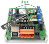
That's it, I am almost done. I designed a PCB for a small cheap ABS enclosure and I received the PCB this week. It is almost a perfect fit, I just have to move the USB connector slightly to the center. Also , I don't know how I managed to get it wrong, but I got it wrong, the Wifi status LEDs are not in the order I expected. Photos are below.
The board is working fine and can be used as either:
- a Wifi controlled RGB LED strip;
- a PIC18F14K50 rapid prototyping board with bootloader and USB and/or Wifi capabilities;
- a USB serial port, wireless if you want.
It has a on-board 5V and 3V3 power supply capable of delivering 1A total. Input voltage can be from 7 to 40V, or over USB. An extension pin header grants access to the unused MCU pins. The three output FETs (IRL540) are specified for up to 100V and can handle 20A easily. Every output can have a flyback diode so switching inductive loads like relays is also possible.
Update 10/10/2014
Finally added the Eagle files and PIC18F14K50 firmware. Sorry for the wait.
PCB, bare, 120718-1
PIC18F14K50, programmed, 120718-41
Module, assembled and tested, 120718-91
Module WizFi220 Serial to WiFi Module (High TX Power), 130076-92
Discussion (8 comments)
HaSch 9 years ago
Hi Clemens,
long time the board was lying in a corner because it always lost the connection to my WiFi after a short time. Now I found the solution, randomly: One have to switch off the powersafe mode of the WIZFi module by giving the AT-commands
AT
[OK]
AT+WRXPS=0
[OK]
After powersafe mode is off the board works nearly perfect. The only thing that is not so nice is that the board always forgots its settings. It would be nice if the settings of the sliders is memorized in the browser interface. In this case you could see the settings every time you start a new browser session and change the colour or intensity. It would be even possible to control the device over internet because there is a immediate feedback.
Can you adjust the interface in this sense? Unfortunately I'm unable to do.
Kind regards,
Hans
KoenBelgium 10 years ago
After a couple of months, suddenly all my modules (2) are no longer accessible via web page. I have reset/reprogrammed both as described in Elektor. Now the leds LINK & OK are on, on my WiFi router I see that they are connected (station list) but do not appear in my IP list and have no access.
When I assign a fixed IP addres I get the same problem. PING gives feedback but accessing via web browser not.
I already used another WiFi router but this gives me the same bad experience. PING ok but web browser not.
What can be the problem because I already ordered two more modules and do not want to end in the same situation?
KoenBelgium 10 years ago
ClemensValens 10 years ago
ClemensValens 10 years ago
antman 10 years ago
antman 10 years ago
KoenBelgium 10 years ago
Hi,
I notice that after a couple of hours/days(?) inactivity the module is no longer accessible via the webpage. On the Wifi module, all leds are out. Has somebody else the same problem and how did you solve it.
Now I need to turn off the power, wait 5 minutes and turn on the power again to have a new connection via the webpage.
Regards,
Koen
HaSch 9 years ago
Markus Künzle 10 years ago
KoenBelgium 11 years ago
I already ordered two kits but fail to soldering the WiFi card on the board. Result is two broken WiFi Cards. Is there a way to order a fully assembled board with WiFi card already soldered?
ClemensValens 11 years ago
clemo 11 years ago
Aragorn33 11 years ago
Hello,
I would love to build one of these boards... but am still fairly new to electronics, so knowing what values certain components are is a challenge. Looking at the schematic, there are several components (C1-C4 for example) that have no values associated with them. The same would go for the crystal (how many MHz is it). Would you be able to provide this information?
Also, more details on the actual connectors would be great, and what they are used for. K3, I understand. K1 and SV1 I am not exactly sure.
Any help is greatly appreciated!
ClemensValens 12 years ago