

Enhancing and extending the Elektor ExC standards
In this article I suggest two enhancements and one extension to the Elektor ECC and EEC micro-controller connector standards. I also propose a simple demonstrator project.
In this article I suggest two enhancements and one extension to the Elektor ECC and EEC micro-controller connector standards. I also propose a simple demonstrator project.
Discussion (1 comment)
JohnHind 9 years ago
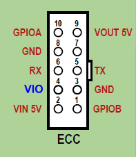
Enhancement 1: Adaptive Voltage ECC.
This enhancement dedicates one of the two unused pins in the ECC UART connector. Pin 4 becomes ‘VIO’. There are four use cases for boards supporting this standard:
A type 3 board can be easily designed using standard USB to serial converters. Using either the FT232R or the FT232H (FTDI) the separate IO power domain (VCCIO) can simply be connected directly to VIO. Using the CY7C65211, the entire chip may be powered from VIO and the USB power just drives VOUT. This avoids the need for level shifters in most cases, but an intriguing possibility is to design a USB to serial interface which is also able to adapt to proper RS232 signalling voltages (+/- 12v nominal). This would require a switchable level converter, perhaps bypassing a standard RS232 booster/converter with MOSFETS. The board should, of course, be clearly labelled with the voltage range it supports to avoid nasty accidents!
A type 4 board is even easier. It can be powered from the connector using a VIN input, VCC output voltage regulator and connecting VIO to VCC. Alternatively, it can ignore VIN and drive VIO from its own PSU. Best of all would be to use a microcontroller to monitor VIN (via a voltage divider) and drive VIO from a GPIO output pin only enabling it when VIN is present.
Extension 2: EBC RS485 bus connector.
For some reason almost all designs using the multi-drop, half-duplex bus seem to have fallen into the habit of specifying discrete wires on screw-clamp wire-to-board connectors. These are nasty, error-prone and time-consuming to work with. IDC ribbon connectors as used for ECC and EEC work nicely in a bus configuration and would be, IMHO, a much better choice.
My proposal is for a new 8-pin EBC standard (8-pin avoids confusion with ECC and EEC whilst making the ribbon wide enough that it is not too fragile). The pins are assigned as follows:
This layout is designed to keep the data wires next to each other and surrounded with ground connections for best common-mode noise rejection. It triples up the cores used for the power supply allowing fairly high currents over reasonably long distances.
My recommendation is to use the ribbon in a ring configuration – a bridge-board would have two EBC connectors to take the two ends of the ribbon which would connect around the equipment in a ring through the other nodes. This way, the bridge-board could carry both terminator resistors and inject power into both ends of the bus on a similar principle to ring-mains house wiring. It might be convenient to have a USB to RS485 converter on the same board as a diagnostic/development/host connection.
Enhancement 3: Direct Board-to-ribbon Connector Option.
In some cases, a direct board-to-ribbon connector such as the Amphenol TMM MicroMatch type will be more appropriate than a two-part connector as used currently. Broadly, these will be better for assemblies that are built once only (or at most torn down and rebuilt a few times during their lifetime). They are smaller in volume, usually lower cost, and provide a more robust assembly. However, two-part connectors remain more useful for rapid prototyping and educational use. I propose that future PCB designs for all the ExC connectors should accommodate either type of connector.
The Amphenol TMM connectors require a staggered pin layout whereas the two-part connectors are rectilinear. However, a PCB footprint could be devised with double-hole pads on one row to accommodate either staggered or rectilinear connectors.
Project.
I feel the need for yet another USB-Serial converter coming on! Oddly with all the converter designs Elektor have published before, none of them have used the ECC standard! I propose a “swiss army board” with voltage adaptive ECC and also a pair of EBC connectors and perhaps EEC for I2C and SPI.
ebc.png (12kb)