ESP32 Digital Voltmeter
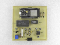
ESP32 - Digital Voltmeter using old style ADC conversion method.
High precision, good stability , negative and positive Voltages !
Range -2V to +2V .
Method of Voltage measurement - Dual slope integrating ADC conversion.
Please read the project updates for more information.
High precision, good stability , negative and positive Voltages !
Range -2V to +2V .
Method of Voltage measurement - Dual slope integrating ADC conversion.
Please read the project updates for more information.
Project Elements
ESP32 DVM7135 - Blynk IOT (PNG, 35.35 KB)
ESP32-DVM7135 Schematic (JPG, 586.39 KB)
ESP32 DVM7135 - Android Bluetooth APP (PNG, 247.62 KB)
Discussion (4 comments)

Gustavo Murta 7 years ago
For a few years I did many experiments with voltage reading with the Arduino. First, I used the Arduino ADC converter and anyone who has tried it, knows that the Arduino ADC is subject to noise in these readings. I do not know by now why, but it is certainly because of the type of ADC (SAR - Successive-approximation-register).
Then I tried out other tests with 12-bit SAR ADCs and 12-bit Sigma Delta ADCs (both low-cost). And I've also been frustrated with both. My dissatisfaction was mainly due to the instability of the readings!
When I was studying one Bench Power Supply circuit, this caused me interest in another type of ADC, dual slope ADC. So I studied the dual slope ADC, in deep. Now there are many other types of modern types of slope ADCs, three or four slope ADCs. My studies directed me to TLC7135, because it is a low-cost digital voltmeter, and I found it in electronics store of my city. Many older DVMs have used this similar Intersil chip. Now there are many other manufacturers, like Texas Instruments.
Intersil ICL7135 (now Renesas)
https://www.intersil.com/content/dam/Intersil/documents/icl7/icl7135.pdf
When I decided to get into the Elektor ESP32 Contest, I thought it was possible to convert my Arduino DVM to ESP32 DVM.
I had doubts with the power supply of the circuit. ESP32 works with 3.3V signals. Luckily, the PCF8574 I / O expander works with 3.3V as well. My question was, but with TLC7135, which voltage range does it work? Seeing the datasheet, I found that the minimum VCC is 4V! But in my tests, I tried with 3.3V and to my happiness, it works very well.The tests previously posted, prove that.
Another surprise to me was with the impressive ESP32 features to generate clock pulses. There are many ways to do this. And very accurate! This made my project easier. Thanks to ESP32.
Reply
Show more
0 Comment(s)

Gustavo Murta 7 years ago
In my project, I'm going to use the TLC715 Voltmeter. This chip should have an external clock. Several circuits I studied, use 100KHz or 120KHz to reject the 50Hz or 60Hz noise. My previous tests with Arduino, I chose 500KHz and the tests were very good. (TLC7135 maximum frequency is 1.2 MHz).
From TLC7135 Datasheet:
"Rejection of 50-Hz or 60-Hz Pickup
To maximize the rejection of 50-Hz or 60-Hz pickup, the clock frequency should be chosen so that an integral multiple of 50-Hz or 60-Hz periods occur during the signal integrate phase. To achieve rejection of these signals, some clock frequencies that can be used are:
50 Hz: 250, 166.66, 125, 100 kHz, etc.
60 Hz: 300, 200, 150, 120, 100, 40, 33.33 kHz, etc."
I want to use 480Khz in this design with ESP32 (50Hz and 60Hz noise rejection). Searching the WEB, I found an ESP32 DCO - Digitally controlled oscillator. I did some testing, and I think I'll use some code from there.
https://github.com/DavidAntliff/esp32-dco
Reply
Show more
0 Comment(s)

Gustavo Murta 7 years ago
As it is the first time I work with ESP32, I'm doing some ESP32 tutorials simultaneously.
And I'm very fascinated with many features, possibilities of using ESP32!
If you are interested:
https://jgamblog.wordpress.com/category/esp32/
https://jgamblog.wordpress.com/2018/02/05/conhecendo-o-esp32-introducao-01/
https://jgamblog.wordpress.com/2018/02/07/conhecendo-o-esp32-primeiros-contatos-2/
https://jgamblog.wordpress.com/2018/02/08/conhecendo-o-esp32-usando-arduino-ide/
Reply

Gustavo Murta 5 years ago
Hi Padakathu,
Suggestions for study :
https://datasheets.maximintegrated.com/en/ds/ICL7135.pdf
https://www.renesas.com/br/en/www/doc/datasheet/icl7135.pdf
http://ww1.microchip.com/downloads/en/Appnotes/00785a.pdf
http://ww1.microchip.com/downloads/en/Appnotes/00781a.pdf
File attached (old) - Understanding the Auto Zero and Common Mode
and more...
Regards,
Gustavo Murta
Reply

PADAKATHU R RANGASAMY 5 years ago
i need two channel measurements, first i tried to read two ICL7135 through two PCF7584, it works reads and give value, then i send to another ESP32 serial2 then string to float
float f = (volt1.toFloat());
converted it is working used for calculation.
But when we swtich on all the time not start reading both PCF7584 data.
Now trying to read from individual ESP32 calculation in one for that need to recive in a variable with polority signed voltage.
float f = (volt1.toFloat());
converted it is working used for calculation.
But when we swtich on all the time not start reading both PCF7584 data.
Now trying to read from individual ESP32 calculation in one for that need to recive in a variable with polority signed voltage.
Reply

PADAKATHU R RANGASAMY 5 years ago
Gustavo, i tried to convert signal and add to voltages. tried to convert using
float f = atof(Signal);
getting error like below
invalid conversion from 'char' to 'const char*' [-fpermissive]
Tried other few ways also still not getting
Please if you have any suggestion to get complete signed float value for calculations.
Thank you
float f = atof(Signal);
getting error like below
invalid conversion from 'char' to 'const char*' [-fpermissive]
Tried other few ways also still not getting
Please if you have any suggestion to get complete signed float value for calculations.
Thank you
Reply

Gustavo Murta 5 years ago
Hi PADAKATHU,
See that :
ESP32 Espruino: convert number to string in different bases
https://techtutorialsx.com/2017/10/26/esp32-espruino-convert-number-to-string-in-different-bases/
Regards,
Gustavo Murta
See that :
ESP32 Espruino: convert number to string in different bases
https://techtutorialsx.com/2017/10/26/esp32-espruino-convert-number-to-string-in-different-bases/
Regards,
Gustavo Murta
Reply

Gustavo Murta 5 years ago
Hi PADAKATHU,
I suggest you create some calculations to convert float in two's complement format.
https://en.wikipedia.org/wiki/Two%27s_complement
void PrintVoltage ()
{
Voltage = ((Digit5 * 10000) + (Digit4 * 1000) + (Digit3 * 100) + (Digit2 * 10) + Digit1) / 10000.0 ;
Serial.print(" Voltage = ");
Serial.print(Signal);
Serial.println(Voltage, 3);
}
Some things may interfere in zero calibration:
Regards,
Gustavo Murta
I suggest you create some calculations to convert float in two's complement format.
https://en.wikipedia.org/wiki/Two%27s_complement
void PrintVoltage ()
{
Voltage = ((Digit5 * 10000) + (Digit4 * 1000) + (Digit3 * 100) + (Digit2 * 10) + Digit1) / 10000.0 ;
Serial.print(" Voltage = ");
Serial.print(Signal);
Serial.println(Voltage, 3);
}
Some things may interfere in zero calibration:
- Voltage reference adjust
- type of capacitor C3 (0,47 uF)
- electronic noise and interference
Regards,
Gustavo Murta
Reply

PADAKATHU R RANGASAMY 5 years ago
Hello Gustavo, i checked for calculations reading stability. Readings are very stable, few issues I want to discuss here
I need to get voltage with signal (+/-) in a float variable for calculations
Tried to convert both voltage and sign to string and the string to float, not succeed, please if you know how to get the voltage with sign for calculation example value1-value2 (+1.580-+1.456).
Tried to send to another ESP32 serial port and done calculation, I want to convert in data Acquiring ESP32 Itself calculation
using 1Mohmm resister inbetween input low and input HI to settle down to zero, some bords not comming to complete zero completely 0.3-4mv floats there
Reply

Gustavo Murta 5 years ago
Hi PADAKATHU,
As you may know, the reference voltage of the ADC converter is the basis of all measurements. So if you need to measure 0 to 200 mV I suggest you change the reference voltage to 200 mV as well. But be careful not to exceed this limit on the ADC input.
Suggested reading:
Tips and tricks for designing with voltage references
http://www.ti.com/lit/ml/slyc147/slyc147.pdf
Regards,
Gustavo Murta
Reply

PADAKATHU R RANGASAMY 5 years ago
Gustavo, checked in your code the milli volt measurement stability, it is perfect and highly stable.
I am planing measure 0-2.0000amps 0.1ohm shunt resister to measure current, the voltage across shunt will be 0-200mv for 0-2.0000amps. Please could you explain which parts (resister capaciter) value need to change to use 200mv full scale (20000 counts for 200mv).
is the BUF OUT pin6 resister instead 100k need to change 10k? if i change reference volt 1.0000v to 100.00mv.
To generate 100.00mv reference, is LM336 2.5v will be stable or i need to use another like LM385 1.2v or TL431
the current measurement will not be continue. press and measure for 4 second. Please advice me the suitable way to measure 2000.0mA current which components needs to change
Thank you
Reply

Gustavo Murta 5 years ago
Hi PADAKATHU,
My conclusion was that the I2C Library of ESP32 was changed in a way that did not follow the protocol. See the original code I developed in 2017. Running perfectly without the artifacts suggested by Chuck. I just upgraded the IDE to 1.8.9.
DVM7135 Arduino Code (2kb)
Reply

PADAKATHU R RANGASAMY 5 years ago
Arduino code posted below, good stable with direct measurement. i will check in different environment and observe. Going to my job, i will check variations in my next vaccation after 4 weeks. if anything updates or anything mistakes in below code please advice me.
Thank you Gustavo
Thank you Gustavo
Arduino code (2kb)
Reply

PADAKATHU R RANGASAMY 5 years ago
Gustavo, working very good. yes i used your code it is really very usefull. thank you so much for spending time to helping me.
In ESP32 working very good and for my curiosity and i have more arduino nano boards i checked with arduino nano also with 500khz clock and rest all same as ESP32 circuit it is working GOOD. Two channel also working good for my experiment. Below attached serial monitor output.
Thank you so much
In ESP32 working very good and for my curiosity and i have more arduino nano boards i checked with arduino nano also with 500khz clock and rest all same as ESP32 circuit it is working GOOD. Two channel also working good for my experiment. Below attached serial monitor output.
Thank you so much
two channel dvm (93kb)
measure in nano (1710kb)
Reply

Gustavo Murta 5 years ago
Hi PADAKATHU,
Good news! Glad to see that your voltmeter is now running. Did you use my code?
The capacitor at the input causes the voltage variations to be slow. You can decrease the value of capacitor C6 to 100nF. If the input voltages vary between positive and negative, disconnect ground from the IN LOW pin.
With calibrations and improvements in a Sketch, more precision and stability you can get.
Post your improvements here.
Regards,
Gustavo Murta
Reply

PADAKATHU R RANGASAMY 5 years ago
Thank you so much Gustavo and Chuck (StickBreaker) for discuss and find solution. i used ESP32 ARDUINO CORE 1.0.1 and now using 1.0.0.
Working GOOD now, reading voltages from ICL7135. checked all three board by follow up the discussed code.
Below attached serial monitor working one photos.
Appart from coding may be due to components i am getting proper voltages when i am connecting 1.5v AA cell, after remove power source when "IN LOW and IN HI free" without any connection to measure also showing near preveous volts and slowly come down. once we toch IN LOW and IN HI then it becomming zero. i followed the components listed in your description C3 470nF polypropylene 400v, C2,C6: 470nf 100v.
Please advice me which components will affect this floating voltages in input.
Thank you so much Gustavo
ESP32 Serial monitor (177kb)
Floating voltages (182kb)
Reply

Gustavo Murta 5 years ago
Chuck (StickBreaker) helped me in Github and solved the problem!
I must change my Sketch.
https://github.com/espressif/arduino-esp32/issues/2949
Conclusion of Chuck :
Don't call Wire() from an interrupt context, Set a flag, then let the main loop do the work.
I can not understand this :
In past my sketch ran perfectly... and now not possible !
Only with new changes
Reply

Gustavo Murta 5 years ago
Hi, PADAKATHU
What is the version of ESP32 Arduino Core ? 1.0.0, 1.0.1 or 1.0.2 ?
I suspect there is now a conflict between I2C and PWM Channel 0 that I use to generate clock of 480 KHz to TLC 7135 (Voltmeter chip). Note that my project worked fine with old libraries.
https://github.com/espressif/arduino-esp32/blob/master/docs/arduino-ide/boards_manager.md
I openned today one Issue at ESP32 Arduino Github:
https://github.com/espressif/arduino-esp32/issues/2949
Regards,
Gustavo Murta
Reply

PADAKATHU R RANGASAMY 5 years ago
Thank you Gustavo for helping me to troubleshoot, i will wait for your check the issue.
i am using from begining 1.8.5 version arduino software as you mentioned version i tried. just now tried with 1.8.9v also and connected as you said pin3 GND to pin9 GND. Uploaded the linked code you given still getting "overvoltages" only continues after connect 1.5v battary.
I will wait for your research.
Reply

Gustavo Murta 5 years ago
While I am researching this problem, you may do a test.
Use Arduino IDE 1.8.5 and ESP32 Board version 1.0.0.
https://www.arduino.cc/en/Main/OldSoftwareReleases#previous
Connect Analog GND (pin 3) to IN LOW (pin 9) - for test.
Measure with 1.5v AA battery at inputs of DVM.
And run the sketch:
https://github.com/Gustavomurta/ESP32-DVM/blob/master/ESP32_DVM7135_PT_V1.ino
Regards,
Gustavo Murta
Reply

Gustavo Murta 5 years ago
HI PADAKATHU !
Today, I was able to reproduce the error that is being presented in your assembly!
I'm using Arduino IDE 1.8.9 and I upgraded the ESP32 board to the version 1.0.2 . And the same problem is occurring - overvoltage!
The I2C interface is crazy. Some change in libraries must have occurred. Please wait while I am researching what was changed to make the interface perform in the wrong way. I verified the error by using the logic analyzer on I2C. Wait for while.
I openned one topic at ESP32 Forum for this problem:
https://www.esp32.com/viewtopic.php?f=19&t=11261
In portuguese at my country (Brasil) :
http://labdegaragem.com/forum/topics/esp32-x-pcf8574-problema-de-leitura-i2c
Regards,
Gustavo Murta
Reply

PADAKATHU R RANGASAMY 5 years ago
Thank you Gustavo for continues helping me to troubleshoot, still facing problem, i followed your instructions to troubleshoot.
Made new neat circuit, double checked faulty components by same IC components working for display in LED using AT89S52. Checked connections voltage supply reference and measured with 1.5v AA battery, no success.
In proto board connected PCF8574 with pin 1,2,3 GND and used 3.3k resister I2C pull-up. Using I2C scanner checked communication was ok 0x20. Then programed “ESP32_DVM7135_PT_V1.ino” code in to ESP32. After program itself start gives “Over voltage” message not even connected clock or strobe in ICL7135. After connected one by one all cables and double check still getting “Over voltage” message.
Please help me to trouble shoot and can I get your earlier Arduino Uno code. i will try in other way. Or is it possible to directly read ICL7135 BCD in Arduino digital input pin without PCF8574. Please find the attached photographs of my steps out puts.
new circuit (1933kb)
new and old circuit (208kb)
new circuit backside (297kb)
after all connection (241kb)
after programed (219kb)
pcf8574 i2c check (173kb)
new and old circuit (208kb)
new circuit backside (297kb)
after all connection (241kb)
after programed (219kb)
pcf8574 i2c check (173kb)
Reply

Gustavo Murta 5 years ago
Hi PADAKATHU If your ESP32 voltmeter is sending overvoltage message, there is a problem. There may be a wrong connection or a faulty component.
I made some modifications for better results. R2 = 18 ohms, C2 = 470nF, C6 = 470nF, P1 = 20K pot. IN LOW pin connected to ground.
You can test the PCF8574 on the Protoboard first. Without any connection to the TLC7135, change the jumpers in the inputs and see the byte in the message output.
https://www.flickr.com/photos/jgustavoam/39420646405/in/photostream/
https://www.flickr.com/photos/jgustavoam/39420488295
Reply

PADAKATHU R RANGASAMY 5 years ago
Thank you sir, i will follow up you for troubleshooting, i connected 1.5v AA dry cell in input of ICL7135 please find the photo attached out put still overvoltages.
Mean time i will make another fresh circuit follow exchatly posted circuit.
Input 1.5v (1275kb)
Reply

Gustavo Murta 5 years ago
Padakathu ,
The reading is correctt ! You put the ESP32 Voltmeter in over voltage condition.
You can only mesure voltages between +2V and -2V. Read carefully the project.
"Tried to connect 2amp 5v usb power and measure the voltage still in -VCC Appears -3.22
between input terminals pin 9-10 measured near zero 4mv.
output at serial monitor showing "Over voltage"
For test, connect 1.5V AA battery at input of ESP32 Voltmeter.
Reply

PADAKATHU R RANGASAMY 5 years ago
Thank you so much Gustavo, for helping me to troubleshoot, double checked the circuits and voltages measured at
ICL7135 pin 01 (-VCC) must be -3.22V
ICL7135 pin 02 (Vref) adjust to 1.000V
ICL 7135 pin 11 (+VCC) must be +3.3V
not connect pin 9 (IN LO) to ground
Tried to connect 2amp 5v usb power and measure the voltage still in -VCC Appears -3.22
between input terminals pin 9-10 measured near zero 4mv.
output at serial monitor showing "Over voltage"
In addition measured with Oscilloscope
Clock out at ESP32 pin GPIO2 480KHZ
I2C scanner detecting PCF8574 (32, 0X20) Address
pulses at SCL 98KZH
ICL7135 BCD out pins binary pulses there
tried to replace the "OverVoltage ();" to "PrintVoltage ();"
printing in serial monitor "Voltage = +15.000" only continuously
Still facing the same problem display in serial monitor overvoltages
Please advice me If anything possible mistakes i may done.
below attached code i downloaded and outputs
output (146kb)
arduino code (2kb)
arduino code (2kb)
Reply

PADAKATHU R RANGASAMY 5 years ago
Gustavo, Thank you for immediate response, i tried first with ESP32 With PCF8574 i2c pull up 3.3k resister followed exactly same your circuit and code 480khz. Clock 18ohms resister at icl7135 pin4. It gives in serial monitor overvoltage only. Then tried with 100khz 27ohm resister at ICL7135 pin4. Still same the strobe frequency only reduced. After many atempt and made fresh connection with double check with ESP32. Then planed to try with arduino clock generated with timer2 100khz and 120khz resister at icl7135 pin4 27ohms used. PCF8574 i2c pull up used for arduino 10k ohms still not reading.
When i check with I2C scanner all time detecting 0x20 adress.
Any issues with laptop usb cable power supply? Still trying to get.
i will try again as you said above points and make fresh circuit and try with external power also. Thank you so much for suggestions. If anything possible mistakes i may done please advice me.
Reply

Gustavo Murta 5 years ago
Padakthu, this design is for ESP32! No Arduino Nano.
How did you generate your clock with Nano? The clock is 480 KHz.
Read the project carefully. Check all connections.
My project is very interesting. And it works perfectly
If you want to use with the Arduino Nano, the resistors should be at 4K7 ohms at I2C.
The positive voltage will be + 5V and negative voltage of -5V.
What code did you use with Nano?
I need to remember my project with Arduino ...
Reply

PADAKATHU R RANGASAMY 5 years ago
Gustavo, Thank you for your very usefull post, i tried many I2C ADC as you said not stable reading. i tried your code to read ICL7135 BCD value. getting only overvoltage in serial print. tried PCF8574 ic with 3.3k pull up and PCF8574 module also, clock generation ok, strobe getting but value unable to read and print in serial monitor. i tried with arduino nano also still not reading from PCF8574, same IC and connections working with direct LED display ok. could you please suggest me what may be the issue and guide me to read ICL7135 adc value in serial monitor.
Thank you
Thank you
Reply
Show more
43 Comment(s)

Gustavo Murta 7 years ago
I was reading today ESP32´s forum about ADCs , and I found some possibles bugs in Voltage readings. So, it reinforced my desire to make my project !
I hope that ESPRESSIF fix theses problems as sooon as possible.
https://github.com/espressif/esp-idf/issues/501
https://github.com/espressif/arduino-esp32/issues/92
https://github.com/espressif/esp-idf/issues/164
https://www.esp32.com/viewtopic.php?f=12&t=2334&p=10942#p11351
I hope that ESPRESSIF fix theses problems as sooon as possible.
https://github.com/espressif/esp-idf/issues/501
https://github.com/espressif/arduino-esp32/issues/92
https://github.com/espressif/esp-idf/issues/164
https://www.esp32.com/viewtopic.php?f=12&t=2334&p=10942#p11351
Reply
Show more
0 Comment(s)
Updates from the author
Gustavo Murta 5 years ago
https://github.com/Gustavomurta/ESP32-DVM
Gustavo Murta 6 years ago
https://www.hackster.io/botletics/esp32-ble-android-arduino-ide-awesome-81c67d
https://github.com/nkolban/ESP32_BLE_Arduino/blob/6bad7b42a96f0aa493323ef4821a8efb0e8815f2/examples/BLE_uart/BLE_uart.ino
ESP32 sends data from the DVM7135 to the Android Tablet via Bluetooth. See attached screen copy. Upload the Sketch ESP32_DVM7135_BLE_V2.INO in ESP32.
I Build my Android Application with Tunkable - very easy to implement. With some modifications of Timothy´s Project. Upload the ESP32_DVM7135_BLE.AIA file to the Tunkable web site. http://app.thunkable.com
Install Tunkable application on your Android device. Export Application APK from site using QR code. To install on Android Device, you must unblock installation on Android configuration.
Once installed, turn on Bluetooth and scan ESP32 DVM7135 device to pair with it.
Open ESP32 DVM7135 application and connect it !
ESP32_DVM7135_BLE_V2.INO:
ESP32 DVM7135 Android Application - screen copy (248kb)
Send Data from ESP32 to Tablet via Bluetooth (3kb)
Gustavo Murta 6 years ago
See attached PCB diagrams - Upper side, Lower side and Silkscreen.
I did some modifications for best results. R2 = 18 ohms , C2 = 470nF, C6 = 470nF, P1= 20K pot.
IN LOW pin connected to ground.
The circuit may be powered by 5V / 1A power supply at micro-USB Connector of ESP32 Module. (ex: Smartphone charger).
Connector CN1 may be used do adapt other circuits, as Voltage divider ou amplifier, Current sensor, ohmmeter, etc. The program (sketch) was unchanged.
My project have many possibilities of use :
GitHUB of Project ESP32 - DVM7135 ( schematics, codes, images)
https://github.com/Gustavomurta/ESP32-DVM
List of Parts :
Module - ESP32 DEVKIT
DVM - TLC 7135
I/O Expander - PCF8574
Negative Voltage Regulator - ICL7660
Voltage Reference - LM336 2.5V
P1 - 20 K linear pot
R1 - 2.2 K ohms 1/8W
R2 - 18 ohms 1/8W
R3 - 100 K ohms 1/8W
R4 - 100 K ohms 1/8W
R5 - 3.3 K ohms 1/8W
R6 - 3.3 K ohms 1/8W
C1 - 10 uF /16V
C2 - 470nF
C3 - 470nF Polyester
C4 - 1 uF /16V
C5 - 1 uF /16V
C6 - 470nF
C7 - 10 uF /16V
C8 - 10 uF /16V
C9 - 10 uF /16V
Wire connections (2811kb)
Connector CN1 identification (2296kb)
esp32-dvm7135-f04.jpg (2350kb)
esp32-dvm7135-f05.jpg (2275kb)
esp32-dvm7135-f06.jpg (2343kb)
esp32-dvm7135-v3.jpg (436kb)
ESP32 DVM7135 PCB - lower side (93kb)
ESP32 DVM7135 PCB - upper side (93kb)
ESP32 DVM7135 PCB - silkscreen (95kb)
Gustavo Murta 6 years ago
I choose Blynk because it is easier to implement IOT with ESP32. Not the best, but it works!
My ESP32 DVM sent voltage values to my Tablet (Blynk application) through the Blynk Cloud Server.
The sending data rate must be at least 1 value per second. Restriction of the free Blynk server.
You must configure the router's SSID and password in that Sketch.
The Token Key is what you can get from the Blynk Application configuration.
Blynk Getting Started Guide ->https://www.blynk.cc/getting-started
Blynk Documentation -> http://docs.blynk.cc/
Blynk Sketch generator -> https://examples.blynk.cc/
Creating Blynk APP project :(see attached screen copy)
Create a new Project
Project Name = ESP32 DVM7135
Choose device = ESP32 Dev Board
Connection Type = WIFI
Theme = dark
Authorization Token will be sent to your email ( insert in Sketch)
Select at Widget Box :
LCD
Blynk LCD Settings : (see attached screen copy)
Input :
Input [0] - virtual pin V0
Input [1] - virtual pin
Messages :
/pin0.###/ Volts
none
Youtube Video - ESP32 DVM7135 Blynk IOT Tests :
https://youtu.be/8PL2q0f5Bow
This is the code I used :
https://github.com/Gustavomurta/ESP32-DVM/blob/master/ESP32_DVM7135_Blynk01.ino
esp32-dvm7135-blynk01.png (35kb)
esp32-dvm7135-blynk-settings.png (207kb)
esp32-dvm7135-blynk-creating-project.png (65kb)
Gustavo Murta 7 years ago
Reading AN017 Application Note (The Integrating A/D Converter - ICL7135), I was reminded that I can make some improvements on the 7135 DVM. And today I made some tests. And to my happiness, I finnaly got the expected linearity and accuracy in my project. I added 27 ohms resistor in series with Integration capacitor (pin 4). I am very satisfied with the results. I also added diode and 100k resistor in series from pin 4 to ground.
In application note :
" Maximum Clock Frequency ( in theory) :
Because of the 3μs delay in the comparator, the maximum recommended clock frequency is 160kHz.The clock frequency may be extended above 160kHz, however, by using a low value resistor in series with the integration capacitor. The effect of the resistor is to introduce a small pedestal voltage on to the integrator output at the beginning of the reference integrate phase (figure 6) ."
The Integrating A/D Converter (ICL7135):
https://www.intersil.com/content/dam/Intersil/documents/an01/an017.pdf
resistor in series with the integration capacitor (29kb)
Gustavo Murta 7 years ago
ESP32 reading BCD data from each of five digits (56kb)
TLC7135 - Strobe pulse and Clock pulses (480KHz) (50kb)
ESP32 reading BCD data from DIGIT 5 (56kb)
ESP32 - I2C interface data (52kb)
+2V at input / CH1=TLC7135 pin 4 CH2 = TLC7135 pin 6 (68kb)
-2V at input / CH1=TLC7135 pin 4 CH2 = TLC7135 pin 6 (70kb)
+2V at input / CH1=TLC7135 pin7 CH2 = TLC7135 pin 6 (67kb)
+2V at input / CH1=TLC7135 pin8 CH2 = TLC7135 pin 6 (67kb)
-2V at input / CH1=TLC7135 pin8 CH2 = TLC7135 pin 6 (67kb)
+2V at input / CH1=TLC7135 pin 21 CH2 = TLC7135 pin 6 (65kb)
-2V at input / CH1=TLC7135 pin 21 CH2 = TLC7135 pin 6 (67kb)
-2V at input / CH1=TLC7135 pin 26 CH2 = TLC7135 pin 6 (60kb)
Gustavo Murta 7 years ago
is combined with ±1 in 20,000 count accuracy and a 2.0000V full scale capability. It features high impedance differential inputs, nearly ideal differential linearity, true ratiometric operation, auto zero and auto-polarity.
These Digital Voltmeter is designed to provide interfaces to both a microprocessor and or a visual display. The digit-drive circuit outputs digits D1 through D5 and multiplexed binary-coded-decimal (BCD) outputs B1, B2, B4, and B8 provide an interface for LED decoder/drivers as well as Microcontrollers.
Analog Circuit (see Analog Section figure) :
A measurement cycle for the TLC7135C consists of the following four phases:
1. Auto-Zero Phase (A/Z):
The internal IN+ and IN- inputs are disconnected from the terminals and internally
connected to ANLG COMMON. The reference capacitor is charged to the reference voltage. The
system is configured in a closed loop and the auto-zero capacitor is charged to compensate for offset voltages in the buffer amplifier, integrator, and comparator.
2. Signal Integrate Phase (INT):
The auto-zero loop is opened and the internal IN+ and IN- inputs are connected to the external terminals. The differential voltage between these inputs is integrated for a fixed period of time. Upon completion of this phase, the polarity of the input signal is recorded.
3. Deintegrate Phase (DE+ for positive voltage and DE- for negative voltage):
The reference is used to perform the deintegrate task. The internal IN- is internally connected to ANLG COMMON and IN+ is connected across the previously charged reference capacitor. The recorded polarity of the input signal ensures that the capacitor is connected with the correct polarity so that the integrator output polarity returns to zero. The time required for the output to return to zero is proportional to the amplitude of the input signal. The return time is displayed as a digital reading and is determined by the equation 10,000 × (VID/Vref). The maximum or full-scale conversion occurs when VID is two times Vref.
4. Zero Integrator Phase (Z/I):
The internal IN- is connected to ANLG COMMON. The system is configured in a closed loop to cause the integrator output to return to zero. Typically, this phase requires 100 to 200 clock pulses. However, after an over-range conversion, 6200 pulses are required.
The other external components needed to make precision DVM are a reference, a clock and a negative power supply.
Reference Voltage:
The full scale reading of 20,000 will occur when VIN = 2 x VREF. Recommended Reference Voltage is 1.000 Volts with high stability for high accuracy absolute measurements. In my DVM I used LM336 2.5V Reference diode with easy adjustment of reference voltage. Use a precision DVM to adjust this voltage.
Clock Frequency :
The clock frequency is chosen to obtain the desired conversion rate, and to maximize the normal mode rejection of power line frequency interference. For both 60Hz and 50 Hz rejection, the 480 KHz was choosed for me. The ESP32 generates this clock pulse with good accuracy. The conversion rate is directly proportional to the clock frequency, with each conversion taking 40,002 clock cycles.
Then my DVM project has a conversion rate of 12 samples/second.
Negative Power Supply:
Since the DVM board is supplied with only positive voltage (+3,3 V), I used the old-style CMOS Voltage converter ICL7660 to supply negative voltage (-3,3v). Simple and efficient for low current consumption. It works fine !
Digital Circuit (see Digital Section figure) :
In my design, the STROBE, RUN/HOLD, CLOCK IN control signals are connected directly on ESP32.
CLOCK IN receives clock pulses from ESP32. RUN/HOLD is used to enable/disable the DVM.
And STROBE line generates interrupts pulses in the ESP32. The other data from DVM is acquired by the PCF8574 I/O Expander. It uses I2C interface to communicate with the ESP32.
The only digit strobe used is DS5 (MSD) to receive data, and the BUSY output is ignored. The STROBE output goes low five times per conversion cycle. Each STROBE pulse of the TLC7135 generates an interrupt in the ESP32 to acquire BCD data and status of Over-voltage, Under-voltage and Polarity lines.
The first STROBE pulse occurs in the middle of DS5 when BCD data for the most significant digit (MSD) is available on outputs B1–B8. STROBE also pulses LOW during the following DS4 through DS1 signals, after which STROBE remains high until the next conversion cycle. Therefore, only one STROBE pulse occurs for each digit select, and each STROBE corresponds to a BCD digit in MSD-to-LSD order. When reading the ADC data, the ESP32 simply reads BCD data during each STROBE pulse and stores that data in memory corresponding to the number of STROBE pulses received.
References :
The Integrating A/D Converter (ICL7135):
https://www.intersil.com/content/dam/Intersil/documents/an01/an017.pdf
ICL7135 and TLC7135 Datasheets:
http://www.ti.com/lit/ds/symlink/tlc7135.pdf
https://datasheets.maximintegrated.com/en/ds/ICL7135.pdf
https://www.intersil.com/content/dam/Intersil/documents/icl7/icl7135.pdf
Simplify A/D Converter Interface with Software:
http://ww1.microchip.com/downloads/en/AppNotes/00785a.pdf
Integrating ADCs: A Tutorial
http://ltwiki.org/files/LTspiceIV/examples/LTspice_cmosedu/_Extras_LTspice/Integrating_ADC/IntegratingADC_tutorial.pdf
Gustavo Murta 7 years ago
tlc7135-integrator-output.JPG (48kb)
bcd-flowchart.JPG (57kb)
Gustavo Murta 7 years ago
Today, I am very happy. I did the convertion of my project from Arduino to ESP32. And it's working !!
Impressive qualities of my project :
Specifications of TLC7135:
http://www.ti.com/lit/ds/symlink/tlc7135.pdf
Now, I will do many tests to improve the circuit. Hablity of access by WiFI and BLT not implemented yet.
My project have many possibilities of use :
First Code (ESP32 - ARDUINO IDE) working with success:
https://github.com/Gustavomurta/ESP32-DVM/blob/master/ESP32_DVM7135_PT_V1.ino
Console Arduino IDE - Positive voltage reading (example)
Console Arduino IDE - Negative voltage reading (example)
Circuit diagram of Digital Voltmeter - ESP32 (432kb)
Gustavo Murta 7 years ago
Today I found a good explanation of using the ESP32 PWM LED with the Arduino IDE.
https://portal.vidadesilicio.com.br/controle-de-potencia-via-pwm-esp32
(in Portuguese)
And I tested this code successfully! 480 KHz with 2 bit resolution and good accuracy.
Gustavo Murta 7 years ago
https://www.flickr.com/photos/jgustavoam/39420488295/in/album-72157665409004158/
I did my first test with I2C Interface using Arduino IDE. And it works !
I2C scanner based on code of Nick Gammon http://www.gammon.com.au/forum/?id=10896
Very simple ! The I2C clock frequency is almost 100 KHz (97.96 KHz). I can't change this.
NOTE > PCF8574 - max frequency = 100 KHz (does not work with 400 KHz).
PCF8574 Datasheet = https://www.nxp.com/docs/en/data-sheet/PCF8574_PCF8574A.pdf
Circuit Diagram - SDA = GPIO_21 and SCL = GPIO_22 .
Very Important = You MUST use Pullup Resistors of 3K3 ohms.
Without then it does not work ! I still do not know, how to configure (Arduino IDE) pullup internal resistors. Change jumpers A0,A1 and A2 to modify address. Default PCF8574 address is 0x20 ( Decimal 32).
Picture of circuit diagram:
https://www.flickr.com/photos/jgustavoam/39420646405/in/album-72157665409004158/
Decoding I2C Pulses with Logic Analyzer :
https://www.flickr.com/photos/jgustavoam/26446652648/in/album-72157665409004158/
I2C Scanner (Arduino IDE 1.8.5) :
Console IDE (115200 Bps)
Gustavo Murta 7 years ago
Dual slope integrating ADCs (and other similar methods) are used in many handheld DVMs until today .
I wish to convert my project to use with ESP32. Then, voltages readings can be acessed by Wifi or Bluetooth ,too. Many utilities of this voltmeter - measure positive and negative voltages , forward and reverse current, etc.
I was very impressed with stability of readings. Both main objetives of my project - precision and stability. With ADC´s Arduino is not possible to do this. Then , I developed this project.
To know some about Voltmeter chip , datasheet bellow: (incredible ! More than 30 years old - since 1986)
http://www.ti.com/lit/ds/symlink/tlc7135.pdf
Sorry my english mistakes.