

ESP32 GPS Car Logger

GPS Logger for my car! Track where you go, whenever you go!
Goal of this project is to get a complete log of where my car was, how far it went, how fast it went, and so on...
It started out as an idea to track some of my activities. Some smaller ideas were done in the past, like tracking my coffee consume or my expenses.
So naturally I figured it was time to step up my data tracking game. That's how this project came to live. Following goals I defined (together with my brother):
- Get GPS Coordinates (longitude / latitude / altitude / time) whenever the car is started / moving
- Write everything on an SD card attached to the main controller
- Provide access to those logs via WiFi (Http or Ftp)
- Show position via LCD or OLED display
- Don't mess up my cars battery / burn my car
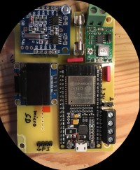
With these points in mind my first prototype around an ESP32dev board was created. It had an ESP32 as it's core component, an OLED Display connected via i2c interface, a GPS antenna (GY-NEO6M) connected via UART and a step-down converter to transform the 12V car battery voltage down to 3.3V for the ESP.
With the next update I'll go on about the first prototype (hardware) and some of the design flaws it had. Furthermore I'll go over the current status of the project, the software and some of the design decisions made.
It started out as an idea to track some of my activities. Some smaller ideas were done in the past, like tracking my coffee consume or my expenses.
So naturally I figured it was time to step up my data tracking game. That's how this project came to live. Following goals I defined (together with my brother):
- Get GPS Coordinates (longitude / latitude / altitude / time) whenever the car is started / moving
- Write everything on an SD card attached to the main controller
- Provide access to those logs via WiFi (Http or Ftp)
- Show position via LCD or OLED display
- Don't mess up my cars battery / burn my car
With these points in mind my first prototype around an ESP32dev board was created. It had an ESP32 as it's core component, an OLED Display connected via i2c interface, a GPS antenna (GY-NEO6M) connected via UART and a step-down converter to transform the 12V car battery voltage down to 3.3V for the ESP.
With the next update I'll go on about the first prototype (hardware) and some of the design flaws it had. Furthermore I'll go over the current status of the project, the software and some of the design decisions made.

Updates from the author
eike 6 years ago
But here is the next update. It will mostly concern the software again, as this was the main focus of my latest work.
First of all, whoever feels like plunging into my work, here you get the chance. I put my software into my gitlab repo, feel free to go through it (it's a little messy and some things aren't really smart, like my event distribution, but it was a nightly first shot, I will rework it. Maybe.).
https://gitlab.herdserv.de/eike/GPS_Logger
So, what's happening there?
1. The ESPAsyncWifiManager connects to my network or starts an AP so I can configure the WiFi.
2. Worker instances will be created (WifiControl, JsonWebSocket,GPSLogger)
3. OTA and and simple FTP will be set up
4. Entering main Loop.
5. Cycle through all worker and call ->run()
WifiControl
The WifiControl mainly manages the HTTP Server. I designed it for another project, where is used to do some UDP Broadcasting to announce it's presence but here it's mostly an HTTP Server. Not sure if I will merge it with the JsonWebSocket worker.
JsonWebSocket
So far not doing too much, will be the receiver and decoder for Json Documents. I plan some dynamic Index.html setup to see the last X log entrys (pushed via websocket maybe), basically mirroring Serial.println(...) while a websocket is connected. A dynamically created Json document will be part of this.
GPSLogger
The actual logger and hardware representation of the Neo-6M Module. Does all the processing and logging onto the SD card / SPIFFS.
The generated Webpage is currently a mix of some easy JS, charts.js and some css thrown together with gulp to reduce it's size. It's also a bit messy but works for me.
David Hughes 6 years ago
Karim Idrissi 6 years ago
I'm really intereseted in your project, it's exactly what I was looking for.
Can you please update the link of the code ? as it's not wokring anymore.
Thanks!
eike 5 years ago
I migrated my own git from gitlab to the more lightweight solution gitea and moved the repos as well. Currently I can't publicly share, but I'm on it to fix that.
Just wanted to say I'm still here, only didn't work actively on this project for a while. But I'm willing to share my code (though I'm sort of embarrassed about the mess).
Until I fix the GIT thing you can use this attached archive of the project...
eike 7 years ago
I wasn't entirely sure at first if I'd actually want to work with the arduino core for the ESP or if I'd rather work with the ESP_IDF framework directly, as it brings more transparency and more flexibility. On the other hand the arduino core brings a ton of ready to use libraries and even more to download out there.
After a short argument with myself I settled for the arduino core simply because of the almost unlimited number of libraries for almost everything I could possibly include in my project. At first I made a little check list what I needed to get the logger going:
SD card? Check. (built in)
OLED? Check. (Adafruit SSD1306, Platformio #ID: 1513)
GPS? Check. (TinyGPSplus, Platformio #ID: 1655)
Wifi? Check. (built in)
Webserver? Check. (ESP Async Webserver, Platformio #ID: 306)
My first approach was is a plain program that constantly waits for new data from the gps antenna to then display and log it. Thrown together in one night it basically worked out of the box (after previous mentioned hardware flaws were worked out of course).
Current program flow sort of looks like in the attached pdf document. There are currently three main worker objects. One responsible for WiFi and Webserver related actions (wifiControl), one dedicated to GPS related tasks (logging) and one to decode and interprete json documents. I will elaborate the software in depth when I actually decide to make it entirely public.
In later stages the whole logger will be controllable via web user interface, all communication between ui and logger will be realized with websockets. The web UI will include something like live updated gps position (lat/lon/alt), sort of a debug page, a file list and some control elements where the log level and target (sd/serial/spiffs) can be changed.
I will not upload my firmware at this point as it is still in mid-development. With my next post I will probably make it public (link to my gitlab page).
Here is a list of all installed libraries which I use in this project:
Adafruit GFX Library @ 1.2.3 [Up-to-date]
Adafruit SSD1306 128x64 @ 1.1.2 [Up-to-date]
ArduinoJson @ 5.13.0 [Up-to-date]
AsyncTCP @ 1.0.1 [Up-to-date]
ESP Async WebServer @ 1.1.1 [Up-to-date]
ESPAsyncTCP @ 1.1.3 [Up-to-date]
TinyGPSPlus @ 1.0.0 [Up-to-date]
eike 7 years ago
- ES-WROOM-32 Dev Board
- GY-NEO6MV2 GPS Module
- SD Card reader
- RTC Realtime clock module
- i2c OLED Display (monochrome 64x128 px)
- MP1584 based step down converter
- additional break out for 3 GPIOs
The attached image shows the first EAGLE diagram I put together. Now, there are a few design flaws which I will now describe. They will be fixed in my next hardware revision.
1.) The RTC Module
Though it makes perfectly sense to keep track of time, it's utterly useless here since accurate timestamps are provided with the GPS signal. Should have known that...
2.) SD Card connection
Technically not wrong but what I did not know at that time was that GPIO 12 is also used at boot time to select NV FLASH voltage.
" If you pull MTDI high on reset then the internal VDD_SDIO regulator will start up at 1.8V not 3.3V. The value of the pin is read before this power domain's regulator is enabled, and before any user code can be executed (as the user code is loaded from flash). "
3.) Additional GPIO break out
Already corrected in this drawing, I started with breaking out GPIO0, GPIO2 and GPIO4. GPIO0 is used to select wether to boot normal or in flash mode (https://github.com/espressif/esptool/wiki/ESP32-Boot-Mode-Selection).
4.) Buffer capacitors
This has already been fixed in the drawing but as you may see in my original picture of the prototype there were no buffer capacitors at first. I did not anticipate the extreme load changes the esp32 can put on the power supply. The module used has a 1amp rating, but as it turned out it's terrible at reacting to quick load changes.
After I fixed those design flaws the board is now actually ready to go. I am working on an updated hardware revision with some more improvements (ideas / contributions are very welcome).
In my next post I will go over the first bits of software.
gpslogger2.jpg (247kb)