
Fading LED a different way
A different approach...
I came up with a different approach to let a LED fade in and out.
When two separate squarewaves, with a slight frequency difference of about 0.5 Hz, are combined, the output squarewave pulsewith will vary between 50% and 100% ("due to phase shifting"). But the LOW state varies between 0% and 50%.
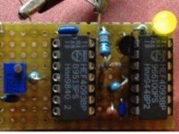
So I used two CD4093 NAND gates, with Schmitt-trigger action, to build two 200 Hz oscillators, one with with a fixed resistor, and the other with a 20 turn potmeter, to be able to adjust a 0.5 Hz frequency difference between them. This results in a linear fading LED, driven by a FET, as can be seen on the video.
The reason why I used two separate CD4093's is the fact that I found out that the schmitt-trigger points are influenced internally by the output sink-current, resulting in 'locking' the two oscillators when the frequency is nearly the same!!!
I tried to minimize this phenomena by separation, but the effect remains.
After decreasing the frequency from 2 KHz to 200Hz, the effect was gone.
This circuit is a bit temperature sensitive, but the principle works well :-)
When two separate squarewaves, with a slight frequency difference of about 0.5 Hz, are combined, the output squarewave pulsewith will vary between 50% and 100% ("due to phase shifting"). But the LOW state varies between 0% and 50%.
So I used two CD4093 NAND gates, with Schmitt-trigger action, to build two 200 Hz oscillators, one with with a fixed resistor, and the other with a 20 turn potmeter, to be able to adjust a 0.5 Hz frequency difference between them. This results in a linear fading LED, driven by a FET, as can be seen on the video.
The reason why I used two separate CD4093's is the fact that I found out that the schmitt-trigger points are influenced internally by the output sink-current, resulting in 'locking' the two oscillators when the frequency is nearly the same!!!
I tried to minimize this phenomena by separation, but the effect remains.
After decreasing the frequency from 2 KHz to 200Hz, the effect was gone.
This circuit is a bit temperature sensitive, but the principle works well :-)
Discussion (3 comments)