

I-Board – poor man's T-board
Thanks to the idea of Andy Tallack we became “free” from the Arduino platform using his T-boards. See his contribution at http://www.elektor-labs.com/project/t-board-ucontroller-prototyping-simplified-130581-i.13808.html
Thanks to the idea of Andy Tallack we became “free” from the Arduino platform using his T-boards. See his contribution at http://www.elektor-labs.com/project/t-board-ucontroller-prototyping-simplified-130581-i.13808.html
Then why did I adapt his design to a I-board for the ATMEGA328?
Because at some stage I like to free my breadbord again for an other design and move the design on the breadbord to a PCB. And I think you like that to do also. At that point I always try to use a poor man's solution: can a holes-print, strips-print or a ready available lab-print be used? If all these solutions become too difficult I start to design a customized PCB. The ready available prints are much and much cheaper (~ 3 euros) than to have a prototype PCB specially made (at eurocircuits or printplaat.nl or ...).
From DIL to SIL
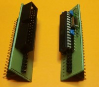
And then I encouter a problem with the T-board. Its headerpins are set in DIL (dual-in-line) format. If I want to use a T-board on a stripsprint I have to cut the strips underneath the T-board and how well I design the print, I always end up with a couple of pins on the “wrong” side of the T-board. They have to marschalled to a extra seperate strip. The I-board for the ATMEGA328 is simply a small board with it's headerpins in SIL (single-in-line) format. Oke, it is a dedicated PCB, but being very small (20 x 60 millimeters) and thus much cheaper than a big dedicated PCB with everything on it.
Furthermore the T-part is gone: no programming interface and powersupply. For programming interface I use a a small simulatorboard with the same pinheader layout in SIL format. By flatcable it is connected to a standard cheap prototyping board (~ 5 euros) for the Arduino. So I can design hardware and software in parallel (as I am used to) using a standard Arduino Uno, connected by its USB port to the programming PC.
The SIL pinheader has 22 pins: the 20 I/O pins (A0 .. A5, 0 .. 13) and pins for GND and VCC. When you use the simulatorboard a jumper on the Arduino prototypingboard let you select if you want to use the 5V power supply of the Arduino or that you provide it from your stripsprint. The ATMEGA328 is most probably not the only chip who needs 1.8 – 5.5V, so you must design that anyway on your print.
Single-in-line and single-layer
Two cheap boards with a SIL connector calls for single-layer boards, further reducing costs. The only consession is that the I-BOARD-ATM has 5 (isolated) wire bridges. Besides them you have to solder the two 22pF caps (C1, C2), a 100 nF capacitor (C3) and the 16.000 Mhz Xtal (Q1). I plan to use the I-board in a future project on a stripsprint which I call YABCC (Yet Another Button Cell Charger), a very not userfriendly charger, but at which I can set all the parameters myself.
Attachments
The photos with this proposal are selfexplaning enough. Therefore there are no schematics. At PCB's you find the layouts for I-BOARD-ATM (where the ATMEGA328P sits with C1, C2, C3 and Q1) and I-BOARD-ARD for the simulator board. Wiring the Arduino prototype board to the flatcableconnector is straight forward, with 1 exception: the wires for I/O 9 .. 13 are “crossed”. Because there is no software you will not find anything here. In the other zip files you will find the gerberfiles and a pdf file how to burn a bootloader in a bare ATMEGA328P using a Arduino, so for every next project you only have to buy a seperate ATMEGA328P (~ 7 euros) not a complete Arduino board. As your project is finished, you pop the ATMEGA uC out of the Arduino Uno and on the I-Board-ATM, which you exchange for the simulatorboard I-Board-ARD which you used so far.
Discussion (4 comments)
JohnHind 10 years ago
It seems to have the disadvantages of the 'T' design (occludes many of the contact points on the breadboard) without the advantages (uses both sides of the 'gutter' so as compact as possible). If you settle for single-in-line why not just a simple vertical board with a right-angle pin header on one edge? This would occlude none of the breadboard, would not be limited in size (could be as high as necessary), and would be simpler to make.
I am still searching for a design that has the same footprint as a DIL package. This would sit in the gutter of a breadboard, or could be inserted on a target board in the same socket as the final IC. However I have not come up with a good design - best I can do is a two-part PCB with a vertical board tabbed into a horizontal board. (This assembly would also be a 'T' shape, but in three dimensions). But that involves tricky corner-soldering by hand.
Thinking caps on guys, we can do better!
AndyTallack 10 years ago
rolandinchania 10 years ago
rolandinchania 10 years ago
sil.jpg (50kb)
rolandinchania 10 years ago