With some modifications we can improve this kit a lot.
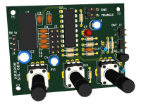
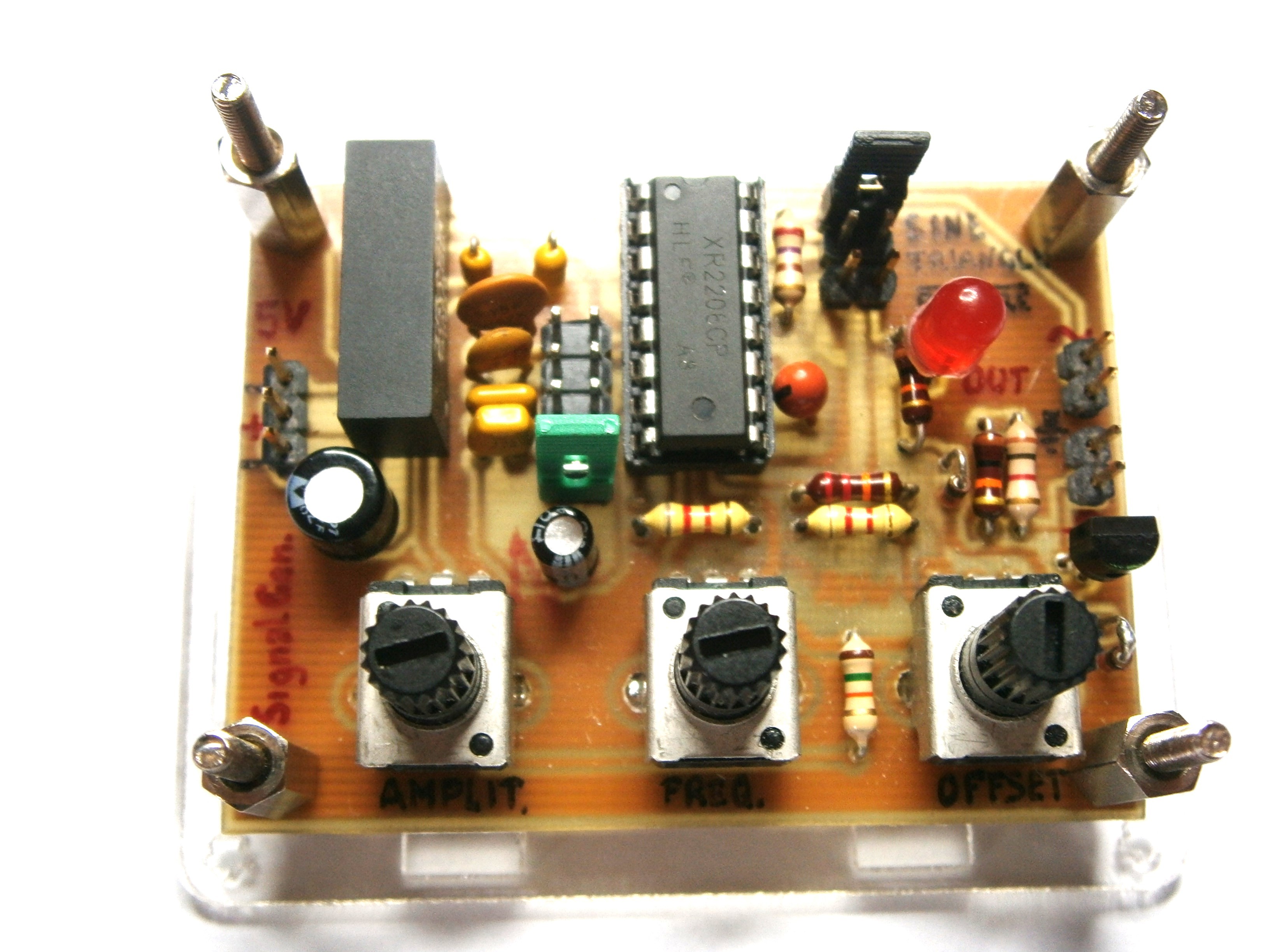
Improve the XR2206 Function Generator Kit
Recently a review of a low-cost function generator appeared in Elektor Labs and for this reason I decided to also publish my personal experience with this kit.
Some time ago I purchased this kit because I needed a small and simple portable sinusoidal / triangular signal generator for basic laboratory experiments. I knew the circuit and I knew I had to make some changes, for example inserting a high value decoupling capacitor at the output because the output signal has a DC offset equal to about half the supply voltage.
What I didn't know, however, was that the XR2206 chip was faulty. I purchased other chips, and they have the same defects, I learned later that the original manufacturer (EXAR and then MaxLinear) stopped producing them and the ones found are probably Chinese clones. The defects of the chips, which I have detected, are two: the regulation of the wave symmetry (pins 15 and 16) does not work, the 25k trimmer as shown in fig.12 of the data sheet has no effect. The other flaw is much worse, these chips cannot be powered with a voltage higher than 11V. At higher voltages the XR2206 becomes unstable and the outputs oscillate uncontrollably (on the kit instructions it is written that "over 12V the signal may not be stable"). At 10V they seem to work well with limited and acceptable distortion for simple experiments.
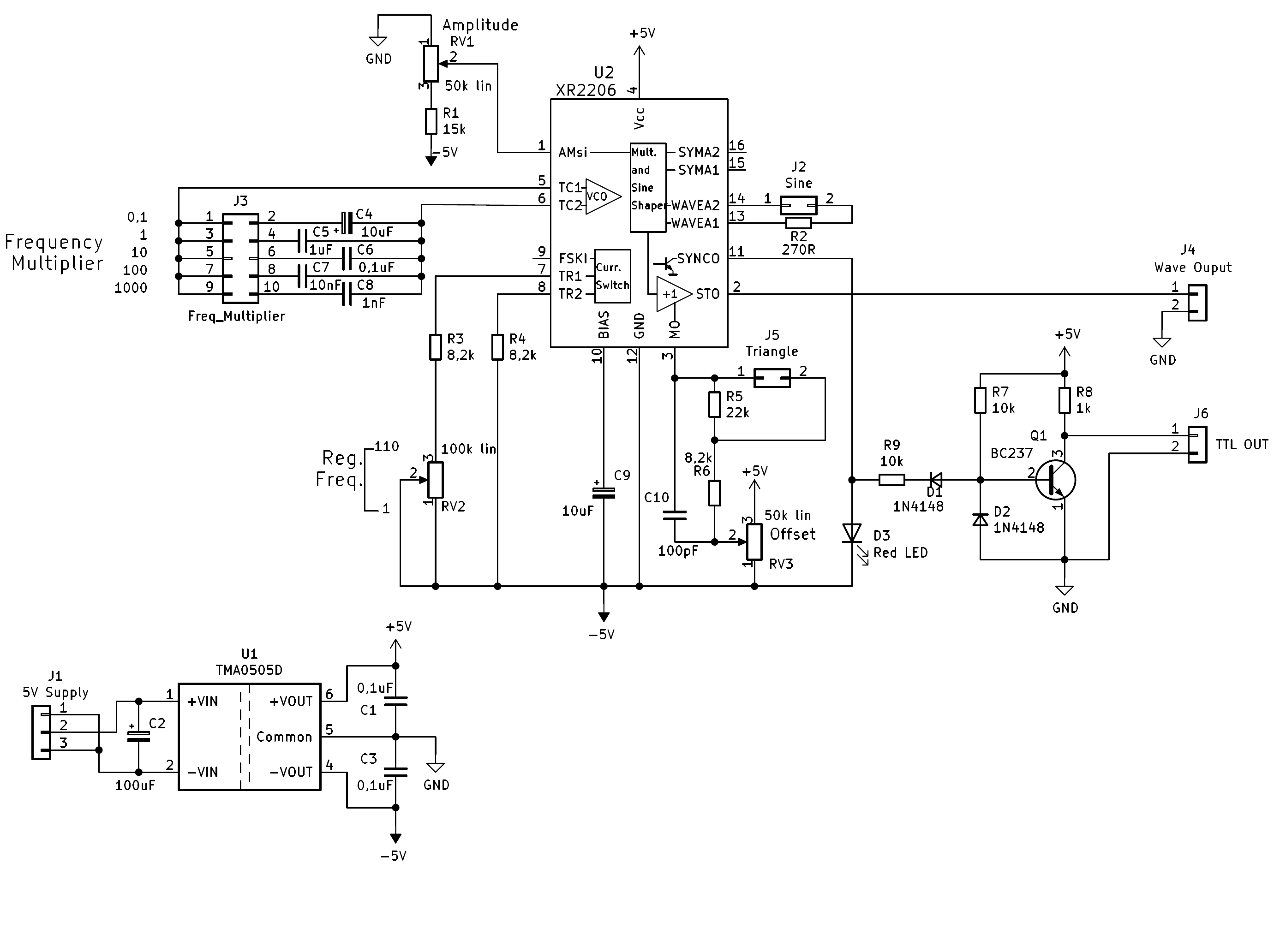
At this point I decided to modify the circuit adapting it to my objective and using most of the components from the kit. I redid the printed circuit with KiCad, the files of which I enclose. The PCB has the same dimensions as the original, it can be mounted on the plastic of the base, but the components are moved compared to the original and therefore the rest of the container is unusable. The modifications consist in the use of a small 1W DC/DC converter (TMA0505D), 5V +/-10% input isolated from the +5V and -5V outputs and a transistor for the square wave output. With the DC/DC converter the current absorption of the 5V input circuit is approximately 70 mA, it is therefore possible to power the generator with the USB of the portable PC (such as Arduino, Raspberry, etc.), from the same circuit under test , from Power Bank or mobile phone charger. The output signal can be injected at any point in the circuit, because the generator is isolated, and the coupling capacitor is not mandatory but optional. The offset adjustment was necessary, the amplitude adjustment changed and the square wave output is limited to a TTL compatible pulsating wave. The red LED diode limits the voltage range on pin 11 to around 1.7V and is used to limit intermodulation noise on sinusoidal and triangular signals (always present on this chip, even on the originals).
The other features and limitations of this signal generator remain the same:
Frequency: from <1Hz to >100kHz in 5 selections.
Theoretical output impedance 600 Ohm (from data sheet).
Measured: Output wave approximately 3Vpp on 1000 Ohm load, 4.5Vpp with no load.
From the oscilloscope screens (attached files) you can see the performance of the circuit, above 90kHz the signal decreases, at 100 kHz it is reduced to 2Vpp on 1000 Ohm load.
Login
No account yet?Register for free!
Forgot password?
Please enter your email address. Instructions for resetting the password will be emailed to you now.

Discussion (1 comment)