Infinite RGB LED Cube with Flowcode

By Ben RowlandAfter being inspired from the Xmas tree blog post I started looking around at what other people were doing and I came across a simple single colour 8x8x8 LED Cube project on Instructables.
By Ben Rowland
After being inspired from the Xmas tree blog post I started looking around at what other people were doing and I came across a simple single colour 8x8x8 LED Cube project on Instructables.
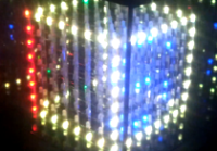
The post was great and looked simple enough so I thought I would have a go at it myself as well as making a Flowcode component to allow me to simulate and easily develop programs for any size of LED cube. I planned on a larger single colour version of the cube but then realised that to double the display meant potentially quadrupling the number of LEDs and connections required and so scaled down my thinking a bit and instead went for the RGB LED approach. This then went further and I thought up a way of making it a useful enough item that I could get away with installing into my living room. Being inspired from infinity mirrors made into tables on YouTube I thought what about we box up the LED cube with glass and mirrored car window tint and create an infinity cube. Installed onto the center of a nice largish second hand coffee table, I might just get away with that one ;)
A step-by-step guide is detailed below, as contributions... more to come!
For convenience sake, all reference files and additional downloads can be found in the main site (here), and not inside the contributions.
--
Coming soon...
We will look into creating some animations to display on the cube using the Flowcode component and look into scripting techniques to allow us to control this via the Flowcode 6 simulation using USB communications or via a file located on an SD card.
--
Videos:
- Simple test routine driven from a ECIO40P
- Basic animations using Flowcode v6
Discussion (7 comments)
Jaime G.-Arintero 11 years ago
In the BOM (see main site) I have listed the common drivers as FETs however I didn’t have any FETs to hand so I instead used TIP122 transistors. A FET would essentially allow the LEDs to run at a much higher efficiency because there is practically no voltage drop across the rails of the FET and so the voltage is nicely shared between the series resistor and the LED. A transistor on the other hand normally has around a 0.7V drop between the collector and emitter which means at high current you are wasting a lot of energy as heat. The TIP122 transistor I am using are pretty bad due to their high current nature having a voltage drop of around 1V. I thought I would try the transistor approach first just because I had them to hand and couldn’t wait, the LEDs are plenty bright and the transistors barely get warm so it’s not all doom and gloom. If I had planned for this I could have dropped my resistor values a bit to compensate for the voltage drop and maintain the 20mA current to the LEDs. Again you live and learn. I’ll get some of the FETs ordered up as I would quite like to have higher brightness and obviously long term this is a more efficient solution. Also because I did the common driver as a separate piece of veroboard it is very easy for me to go in later and replace/upgrade any of the inner workings without having to disassemble everything. Checking each LED was still working ok using the test routine below I then covered the exposed pins of each LED with some electrical tape just to avoid any potential shorts if things start to move around inside the compartment. The schematics I used to connect everything up can be downloaded in the main project site.
I used some pieces of veroboard to allow me to connect an ECIO directly to my 5V power supply and to create the common drivers. A 5V power supply must be used to allow the large current to flow without generating any additional heat. A standard low dropout regulator would likely become far too hot to go near and would likely burn out depending on the input voltage and drive current. For the final version I intend to use something with a bit more beef so maybe an AVR, an ARM or a dsPIC from the new EP range. The Flowcode LED Cube component is flexible so will work with pretty much any microcontroller family apart from 8-bit PICs as these cannot have arrays greater then 256 bytes in size. I made sure that I socketed my microcontroller to allow me to switch devices easily without having to re-make another host board.
I used some chunky bits of wood with 45 degree cuts to create a frame that I screwed onto the underside of the LED base and then carefully placed the electronics into the frame and padding appropriately with some bubble wrap so things didn’t rattle around. Using some thinner pieces of wood I created a bottom to keep the electronics in place when lifting the cube, this then got screwed in place. Remember to add a hole to allow your power supply to be connected. Some of the popular switch mode power supplies come in small metal cases so this could also be included inside the box to neaten things up a bit. You may also want to leave the USB cable connected to the ECIO to allow you to A) reprogram without having to re-open the casing and B) for communications via USB should you want to go down this route using the Flowcode USB components.
Jaime G.-Arintero 11 years ago
With the cube carefully shifted upside down and rested on the glass (ask a friend for help just in case the glass is a bit loose) I started work on the wirings to connect my circuit boards from Part 1 to the LEDs. Each LED leg was bent at a 90 degree angle to secure the LED in place against the board. With each LED I bent one leg to the left, one upwards and the other to the right. I then sanity checked that all the LEDs were bent the same way so I could be sure of the colour assigned to each pin.
I then took the 8 x 24 way ribbon cables connected to the driver boards from Part 1 and carefully split the cables into sections of 3 before splitting up the ends into singular cables and stripping around 3mm of insulation from the ends. As long as you are consistent and wire RGB or BGR for every single cable then the wiring will work fine with the Flowcode component. If you mix and match the wiring then you will have problems. Remember that we used a slightly larger series resistor to drive the Red channel so this can be used as a guide to double check your wiring the right way. Once the anode wiring was done, the cathode wires were cut down to a reasonable length and bent out the way. I connected some lengths of fairly thick cable to each of the cathode wires and the covered the remaining bare wire with electrical tape.
Try and keep the ribbon cables between the drivers and the LEDs and between each driver board as short as possible without making them too short otherwise you will start having problems with the buffer drive chain where some values may get updated out of sequence on the chain due to cross talk. If you do start having these problems then try and separate the individual cables as much as possible using tie bands. If there are still problems then maybe look into applying some kind of grounded shielding to the cables using foil or metal mesh, if you do then this be careful to try and eliminate any potential for shorts so your power supply doesn’t go up in smoke. My cube with neatened up wiring works well and only seems to have a cross talk related glitch about once every 100 refreshes or so which is fine for me. Before I started with the neatening and reducing of the ribbon cables I was experiencing monumental glitches on every single update.
20140103-234526.jpg (200kb)
20140106-001107.jpg (206kb)
Jaime G.-Arintero 11 years ago
As each complete panel was finished I made sure to give it a full test while it was still in the jig to ensure that every LED lit correctly and that there were no breaks or shorts in the panel. To do this I connected long lengths of wire to my 5V power supply. At the end of one of the pieces of wire I soldered the larger of my two resistor values used on the driver board from Port 1 and this allowed me to drive all of the LEDs without any risk of damage. Using my trusty metal ruler pressed against the unconnected common leads shown above on the left I was able to temporarily short all the common pins together to ground meaning I only have to test each column pin once rather then having to test each and every LED individually. To get the panel of LEDs out of the jig I just gently pushed on the top of each top LED in turn and repeated until the entire panel popped loose.
After all the LED legs were bent and all the LEDs were assembled into panels it was time to start joining the panels together. I laid the first panel flat on a desk and soldered two lengths of straight wire to each the cathode wires one at either side of the panel to provide a good level of support and a bit of redundancy just in case one of the solder connections on one of the wires were to fail. To obtain the straight wire I used the technique of holding both ends with a pair of pliers and pulling hard. I had to experiment with a few different types of wire before I found one that would be happy with the current from 64 x 3 LEDs and would also straighten nicely without too much effort on my part. The wire I ended up using was enamelled so rather then sanding it off I simply put the pieces of wire into my wood burning stove for 10 mins while the enamel burned away. After each cathode wire were connected and checked for straightness I used a few small cigarette filter boxes to space the next panel away from the first. Taking my time to ensure everything was as lined up as possible I repeated this process until all of the panels were together and then gave the LEDs another full test to ensure I hadn’t missed anything. 9V batteries are also meant to be good for using as spacers so long as you tape off the terminals so you can’t blow any of the LEDs with the excess voltage.
The cube once fully assembled is fairly strong but all it would take would be a bit of weight applied in a wrong place and all that work would be ruined. I used the same piece of MDF board that I used to create my jigs and drilled 5mm holes into this at the correct pitch for the legs of the bottom row of LEDs to go through the MDF. To work out the pitch I took measurements from outer left LED to outer right LED on both sides of the cube and then averaged the spacing, then repeated for front to back. I then drilled a further 8 x 3mm holes along one edge for the cathode wires to come through to the cube. I also routed a 6mm groove for my glass cover to fit into and spray painted the wood as this would be near impossible after the LEDs are mounted. Finally I used some of the mirrored tint detailed later on to provide a mirrored effect to the top surface of the painted MDF and poked holes in where the holes had been drilled. I thought about routing a nice shape onto the edge of the base but by then it was getting dark outside and I was eager to move onto the next stage.
I had thought getting the legs of the LEDs through the holes in the base would be easy, I was wrong… :(
The only way I could do it was to use a small object like a TV remote control to wedge up one side of the cube leaving me free to tease the legs on the other side of the cube into the holes a panel at a time using my trusty tweasers. Once an entire panel was in I moved the remote a bit, applied a small amount of pressure to the top of the cube and then moved on to the next panel. After doubling back a few times I had most of the wires in the holes and after a bit more checking and teasing I managed to get the entire cube in and flush with the base board. Phew. This is very frustrating so I would advise getting into the right frame of mind before starting this part of the build and then to take your time as much as possible to avoid any unnecessary stress and damage to your solder joints. A joint failing near the center of the cube might mean you have to take it back off it’s mounting base and unsolder some of the panels so anything you can do to avoid this is worth doing. Saying this I was not all that patient with mine and it happily took a fair deal of abuse with no real negative consequences. Thinking about it if you have access to a stepped drill bit or similar then it would be possible to cone the holes slightly and maybe make it easier to get the legs into place. Either way you’ll get them in there eventually and can have yourself a well deserved rest.
complete-panel.jpg (182kb)
Jaime G.-Arintero 11 years ago
For anyone who wants to replicate the project but without access to a 3D printer they can use the build method documented here. I recommend you read through this anyway as it covers the build process better then I ever could.
The first step for assembly was to take all 512 LEDs and bend them correctly. To do this I drilled a 5mm hole in a piece of wood and checked that a LED fit snugly and flush to the wood but could also be removed easily. Once I had my hole correct I draw some guide lines to help with the bending. The lines I drew were one vertical running through the centre of the hole, one horizontal line running through the centre of the hole and one horizontal line running through the very edge of the hole. A metal ruler came in very handy during the bend stage. The pictures below show the jig to bend the LED as well as the steps to follow when bending the LED’s legs.
Insert the LED into the jig ensuring you have got the LED in the correct orientation. The pins should all be sat on the first horizontal line and the cathode pin should be the second pin from the left.
bending-jig.jpg (67kb)
1st-bend.jpg (36kb)
2nd-bend.jpg (43kb)
3rd-bend.jpg (204kb)
Jaime G.-Arintero 11 years ago
As I’m making a 8x8x8 LED cube we will need at least 512 LEDs to complete the project plus a few spares just in case we damage any of the LEDs or find some duds. I got the 5mm, common cathode, diffused RGB LEDs shown below for around £30 (around 37€ / $50) for 600 LEDs on eBay they say they are diffused but other reports lead me to believe that they are not as diffused as you might like. One method of add extra diffusion might be to sand the LEDs slightly using fine grade sand paper or roughly cut the top off the led using a saw. For 512 LEDs this might be a big task to get them all uniform so I will see what they look like when they arrive before deciding what to do with them.
To save on the number of signals we need to control the individual LEDs (512 x 3 = far too many to think about) we will use a multiplexing technique to only light a single row of 64 LEDs at any one time. If we can strobe each row fast enough then persistence of vision will allow the entire display to appear static to the eye. The instructables article linked above covers this technique very well so I recommend you look there if you want to know specifics.
Controlling 64 RGB LEDs is no easy task considering each LED requires 3 signals to drive each colour channel. This totals up to 192 control signals which is much higher then the I/O count on most microcontrollers. To allow us to do this I have created a custom PCB design using Proteus which can be used as a template for your own home made PCBs. Alternatively you could do the board using veroboard and roadrunner wire as shown in the Xmas tree post. The PCB design features 3 x 8-bit buffer ICs which can be used to store the state of 24 individual outputs or 8 complete RGB LED signals. The 8-bit data signals are passed from one buffer to the next by using a clock signal and the boards can be chained together using ribbon cable to create a display of any size. For my 8x8x8 display I need 8 boards connected together to drive the 8×8 lower row of the display. The modular driver board technique requires just 10 control signals from the microcontroller to function, 8 to form the data bus and an additional 2 signals for the Chip enable and clock signals. The remaining 6 wires on the ribbon cable are used to pass the 5V and Ground supply rails to the driver ICs. Details of the board can be found in the attachment at the end of the post. A further board could be used to drive the cathode FETs but for 8 rows we can probably get away with just using a spare microcontroller port.
I had my PCBs made professionally from Eurocircuits for about £120 for 20 of the boards. Its very nice to have professionally made PCBs as you know they will work correctly without a lot of effort but they could be made much cheaper by using home made PCB methods such as drawing with a permanent marker onto photo sensitive PCB boards before exposing in a UV box and then etching. CNC made PCBs are a good option too. It’s been a while since I made my own PCBs but if you take your time they generally work a lot better then they look.
You may want to see a picture of my controller boards connected together using DIL headers (below, under 'photos'), IDC connectors and ribbon cable. The top board has the 24-way IDC cable fitted but the other boards are currently missing this.
leddriver.jpg (179kb)