
Interrogation lamp (or possibly a bicycle light) [140002-I]
On discovering that my previous design based on a blocking oscillator and diac strobe pulser was a bit heavy on the battery, it seemed about time to attack the problem from a different angle with an oscillator that is easier to tweak for the most favourable characteristics.
On discovering that my previous design based on a blocking oscillator and diac strobe pulser was a bit heavy on the battery, it seemed about time to attack the problem from a different angle with an oscillator that is easier to tweak for the most favourable characteristics. Also, a stobing front light on a bicycle is rather less useful than strobing at the rear.
The oscillator chosen for this project is the age old and time tested complementary astable, many people build this circuit without the 10R resistor between Q1-C and Q2-B, but this means that Q1 tries to dump the charge of any supply decoupling capacitor into Q2's B/E - the circuit would object quite strongly to this! The prototype was built and tested without a decoupling capacitor and exceeded expectations, but 100uF or so might come in handy if the battery leads are more than a few inches. In its simplest form, this oscillator would drive narrow spikes of current through the load, this trait is modified by the inclusion of the 220R resistor in series with the timing capacitor. Obviously it is neccessary to widen the pulse from a mere spike in order to pump some energy into the inductor.
Essentially this has been a largely junk box project, so some effort has been made to accomodate constructors whose junk box isn't as interesting as mine. This oscillator is quite capable and could probably boost 2 cells to drive a white LED without the output pair, but then Q2 would have to be carefully chosen to handle the current peaks, and then of course Q1 would need selecting as being capable of driving Q2, by shoving the heavy lifting onto transistor pair Q3 and Q4, Q1 and Q2 can be pretty much any more or less similar PNP/NPN pair, it is highly likely that anything in the historic TUN/TUP designation would do the job. Q4 is pretty much any convenient NPN transistor in a TO126 package, something might be found in a TO220 case that will do the job but if its too hefty Q3 might have to be beefed up to drive it properly.
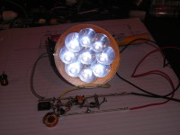
This circuit will drive a bank of paralell white LEDs, the prototype was put through its paces with a 9 LED array/reflector salvaged from a £0.99p headband worklight bought from the Family Bargains store chain, this had not given quite the results hoped for when used as a test load for some other prototypes (now dropped) - but on this circuit the LEDs are bright enough to be painful to look at. The circuit has been tried with a TO220 style (allegedly) 3W LED bought from Maplin some years ago, the circuit clearly has no problem driving one single power LED, maybe a 1W puck would give better results than the TO220 style LED, a 3W puck would be wastefully under utilised.
The bit most likely to frighten anyone is the inductor, an examination of a cheap 2D LED flashlight revealed a tiny (disguised as a resistor) choke, marked as 47uH. It was clear from the outset that such a tiny component wouldn't handle the power being aimed for, but the inductance of 47uH seemed as good a place to start as any. A search of the junk box turned up a 32uH ex-motherboard toroid, and a 51uH ferrite bobbin ripple choke from an old switch mode PSU. Both were tried and any difference between the two wasn't obvious. A higher inductance can be used if the timing capacitor is increased, but at about 10nF or so and you're getting into the top of the audible range.
all testing was done with a pair of AA Ni-Mh cells, its obviously the most economic option but its worth remembering the "sudden death" discharge curve of nickel chemistry batteries, although this is compensated to some extent by the boost converter, so you'd probably lose more than you gain by using alkaline.
Its worth stressing at this point that using nickel batteries with their "sudden death" discharge curve in bicycle REAR lights is a really bad idea!
I was notified of a problem with this design, which I replied to immediately - but heard nothing since.
It seems to have fallen between the cracks!!!
Discussion (2 comments)