

IR Remote Control Learning Dimmer or Heat Control [140279-I]
This circuit has the following features: it works with the main frequencies of 50 or 60 Herz, it works with the main voltages of 117 or 220 VAC, it is connected in series...
This circuit has the following features:
- It works with main frequencies of 50 or 60 Hertz.
- It works with main voltages of 117 or 220 VAC.
- It is connected in series with the load and can replace any conventional switch without any modifications.
- It works with only one switch.
- It can control the brightness level of any heat element, incandescent or alogen lamp.
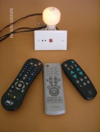
- It has the ability to learn up to four control codes of a common infrared control.
--> look for the file description.zip in others files
I updated the sofware: now it has the capacity to store 8 codes!
I want to thank Ton for his help to modify the circuit to operate with 230 VAC as well as by his valuable time and effort that help me to detect some bugs in the code.
Discussion (3 comments)
vishal gupta 8 years ago
Please share 2.0 version circuit link if possible and possible to add opto for zero crossing detector.
TonGiesberts 8 years ago
TonGiesberts 10 years ago
front-view.JPG (479kb)
rear-view.JPG (567kb)
TonGiesberts 10 years ago
We were charmed by the idea of a dimmer that can learn codes from practically any remote control. After some changes in the schematic to make sure the circuit can handle 230 VAC with standard parts (specifically resistors), we designed a PCB and tested the circuit (Schematic v1.0). To our surprise R5 and R6 burned out immediately. It took some measuring and thought about what could be the cause of this. Obviously there’s more current flowing through C2 than theoretically is the case with just 230 V at 50 Hz, and should be less than 50 mA. At some point it dawned to us that it must be the triac (TRI1) somehow. Depending on the moment of triggering and polarity of the mains voltage, capacitor C2 is discharged through D1 (and the rest of the circuit) or D2. This means at peak voltage the current (spike) would be more than 60 A. Of course the triac and C2 can’t handle this for long and certainly not two little ¼ W resistors (R5/R6). Also the working voltage of standard ¼ watt resistors is often not more than 250 V. In the case of 230 V mains this should be more than 350 V. That’s why the discharge resistor parallel to C2 is divided in to two in series. Also the original resistor in the divider for the zero crossing detection is split in two for the same reason.
To make connecting cables easy and taking high currents into account we used faston type connecters that are screwed onto the PCB. In principle with a different inductor (e.g. 22 µH/11 A , 1422311C from Murata Power Solutions) and a higher heat sink (lower thermal resistance) for HS1 even 10 A is possible. The footprint for the radial inductor L1 has two different lead spacing’s. For the heat sink a Fischer SK 129 63,5 STS can be used. It has a thermal resistance of 4.5 °C/W. Together with the junction to case and case to mounting-base thermal resistances the temperature of the junction will get over a 100 °C (environment temperature 25 °C. For long term use this is to high. A good rule of thumb is a junction temperature should not go beyond 70 °C. In the case of maximum loading (10 A) forced cooling is advised. In our present design with a 5 A maximum and 6.5 °/W for the heat sink the junction temperature will be around 65 °C or so. This depends largely on the environment temperature. especially inside an enclosure. If a fuse with a higher current rating is used the text on the PCB should be changed (take a little sticker with the correct value and place it on the present 5 A T value).
To solve the problem with the excessive dissipation in R5 and R6 in schematic v1.0, in schematic v2.0 C2 is directly connected to the mains. We already placed the direct connection between the load and the mains terminal on the PCB to make wiring easier. It’s also easier this way to make other connections parallel to the load and/or the mains. The two resistors are replaced by a single 1 W/350 V resistor. On the PCB however is room for two standard ¼ watt resistors (2 x 47 Ω) in series.
The original gate resistor R2 of 22 Ω has been increased to 120 Ω, a lower value will seriously overload the respective processor pin. The triac BTB16-600SWRG is a digital one (suffix SWRG) and has a more sensitive trigger current of 10 mA (min.). Downside is it’s not snubberless, hence the need for RC network R1/C1.
After extensive testing and tweaking of the software (by Juan) we finally have a good working dimmer that that can learn most codes of remote control. To control and enter the program mode the two buttons are horizontal tactile switches and are placed on the edge of the board. These buttons have an elongated shaft and extend about 11 mm beyond the edge of the PCB. This way if they protrude through a plastic enclosure with the PCB at maximum distance, we can be sure the construction has a class II isolation. The transparent enclosure should also be transparent for IR light, then there’s no need for an extra hole for the IR receiver IC2. It’s located right next to S1 and S2 at the edge of the board. The triac can be directly mounted onto the heat sink. It's connected to terminal A2 which is also connected to the metal tab of the TO-220 case. Use a small amount of thermal compound to lower the thermal resistance between heat sink and triac. To make the electrical resistance of the solder joint of A1 and A2 of the triac lower, extra openenings are made in the solder mask to make it possible to solder the pins flat to the PCB. There’s a hole, in both L1 and the PCB, to mechanically fix L1. A plastic 4 or 5 mm screw (at least 27 mm long) can be used. Don’t use a metal screw here!
In case a little flickering is visible when dimmed try lowering R7 and R8 (schematic v2.0) to 220 kΩ. Also increasing the value of C9 can help (< 10 nF). A larger value will cause a larger shift in the triggering point of the triac.
Warning: the whole circuit is connected to the mains! Never work on or touch the circuit if it's still connected to the mains. Unplug first.
We placed two versions of the software: -11 learns 4 codes and -12 learns 8 codes.
Programming the circuit is easy. Just push S2 for about 3 seconds and push 4 (or 8) buttons on one or more remote controls. To signal the circuits enters programming mode the lamp will go on and off twice. Each time a button is pushed the lamps briefly lights up.Some remotes send a full data set the first time a button is pushed and just a repeat after that. Push the same button on the remote two or more times. This also needs to be done for the RC5 code (has a toggle bit).
A build-in prototype is yet to follow.
Would be nice if Juan could tell us more about the software…
140279-1-ir-remote-control-schematic-v200.jpg (1155kb)
Topoverlay of PCB 140270-1 v2.0 (35kb)
Copper on bottom of PCB 140279-1 v2.0 (12kb)
Software for 4 remote control codes (33kb)
Software for 8 remote control codes (41kb)
140279-51.jpg (308kb)
140279-52b.jpg (173kb)
Juan.Canton 9 years ago
AADiSanto 9 years ago