

Irrigation Controller

Let's face it: I'm a poor gardener. This project shall help me watering and monitoring the plants on my balcony.
Introduction
Let's face it: I'm a poor gardener. My main problem: Forgetting to water the plants. I'm thinking about this problem for many years now. Many ideas came to my mind, but I didn't actually start something in this regard.
In 2017, sometime between spring and summer, I stumbled across the Gardena MicroDrip system. It's a starter-kit that uses a (indeed very very small) pump within some sort of water reservoir. The last part was pretty important, because my balcony has no direct water tap. The kit came with some pipe, some drippers, the water pump and a very basic controller. The controller is able to do some fixed-interval programs, but you can't freely program it.
I'm aiming at more flexibility in regard to watering the plants. The basic idea is still to use fixed intervals, but drop waterings in case of rain or extend the watering time if the sun was shining heavily.
Goals
In the first step, I'm going to implement just the fixed interval watering. That's more or less what the simple Gardena controller can do, but with the addition of monitoring the water reservoir. This will allow me to receive alarms, when the water level is too low. Additionally, the pump won't run dry anymore as it does with the Gardena controller. This is what I expect to be completed within the competitions' runtime.
At a later stage - after the competition, the second step will be adding more advanced logic to make the watering more flexible. The basic idea will be to still to use fixed intervals, but drop waterings in case of rain or extend the watering time if the sun was shining heavily. I'm planning to address this step much later this year.
Hardware platform
My hardware platform is based on an ESP32. I designed a base board with some relays, power supply, UART interfaces (for sensors, e.g. the fill level sensor for the reservoir) and the ESP-WROOM-32 module.
On the top edge of the board are connectors for power, the relay outputs and the UARTs. The connectors are screw terminals which can be disconnected without loosening the screws, which might be handy when installing the hardware in its IP67 enclosure.
The design has two switching regulators: The first one is the main regulator for the 3.3V I use to power the ESP32 and all other digital stuff on the board. The second regulator is used to power the relays and external sensors. This regulator is normally off and can be activated via a GPIO of the ESP32. The UART level-shifters are also held in standby by default and can be powered up by the ESP32 on demand. I did this to reduce the power consumption as much as possible. I plan on driving the whole system on solar power sometime in the future. That's also the reason why I connected an ADC channel to the power input for voltage monitoring.
The fill level sensor (which is another project on its own) will be connected to one of the UARTs. Measurements will be triggered via a simple command/response scheme. I decided to decouple the two projects to try out different approaches for measuring the fill level in the real world. With the use of a generic command interface it doesn't matter how the level is actually measured.
Project resources
The software source code is published on Github where I will also publish up-to-date documentation: https://github.com/mwick83/irrigation_ctrl
The hardware will also be published on Github: https://github.com/mwick83/irrigation_ctrl_hw
I also blog about the project on my website under the hashtag #IoP - Internet of Plants.
Updates from the author
mwick83 6 years ago
I did have a minor issue lately regarding SNTP: When powering the system up, the SNTP sync didn't work out (due to bad WiFi reception). The implemented logic scheduled the next sync four hours in the future. Therefore, with the default time set, the first irrigation happend at the wrong time. I changed the SNTP resync logic, so it will try to resync every 10 minutes in case an attempt failed.
So, what's missing from my first plan until the end of the contest? The reservoir fill level sensor didn't work out. I am planning a different approach for the future: I intend to measure the static water pressure within the reservoir. That seems to be what professional sensor do as well. I already looked around for sensors and found a candidate from NXP. What's causing me headaches is how to mechanically connect the reservoir with the sensor and making the sensor water-proof for outside use.
I also ordered some Bluetooth LE plant sensors (Xiaomi Mi plant sensor), which are able to measure moisture, temperature and light intensity. The ESP32 with it's bluetooth capabilities seems ideal to connect the sensors locally to it.
mwick83 6 years ago
As a side note: The switch to CEST last night worked without a hickup!
mwick83 6 years ago
SNTP request are now fully controlled by the IrrigationController. This is due to the fact that a time update could cause an active irrigation to be canceled. Therefore the IrrigationController plans SNTP updates if irrigation is idle and upcoming events are far enough in the future (60 secs are currently configured).
Some other misc fine-tunings I did:
Wakeup times have been corrected and separated for deep sleep and non-deep sleep cases. Previously, events have been missed after deep sleep, because lastIrrigEvent wasn't preserved and was initially set right after the event, we were wakeing up for. Wakeup times should now be better and lastIrrigEvent is now also stored in RTC memory (storage mechanism needs to be refactored later).
I also increased the polling interval when near to an event. Otherwise MQTT updates are sent pretty often and start to flood the network. With the now stored lastIrrigEvent (RTC mem), overshooting shouldn't bee too much of a problem anymore. Startup-time (non-deep sleep) is something around 600 ms, with a polling interval of 500 ms we can be off by 1100 ms at most.
My serial logger and Raspberry Pi relay output logger are running again. I hope I got the algorithm stable now.
mwick83 6 years ago
That's the reason why I implemented configuration options to disable battery monitoring and/or reservoir fill level monitoring. If one is disabled, it will not take part in the decision if an irrigation should take place or not. This not only allows continuing with the development regardless of the fill level sensor, but it also adds more flexibility in the hardware setup.
One other missing piece in the software is proper SNTP handling. The control logic requires to be notified of changes in the system time to work properly. Manually setting the time through the debug console is no problem at all, because I have all the software under my control. But the SNTP implementation is part of the lwIP stack used in the ESP-IDF. It doesn't signalize any state changes at all. According to a discussion on Github, I'm not the only one needing such a feature and it looks like it's already in development. I hope it will go public soon. Otherwise, I would have to patch the ESP-IDF sources, which would not be publicly available.
mwick83 6 years ago
I have chosen to publish the voltage and reservoir fill level in mV and "percent multiplied 10" to prevent the usage of floating point variables as much as possible.
mwick83 6 years ago
I'm using a slightly modified version of the gpio-monitor found on the Raspberry Pi community forum. Other than that, a serial monitor connected to the debug console is logging the debug output of the controller itself as well. That should give some insight in case something goes wrong.
Here's an example of logged events (time is displayed in UTC): The start of each line displays the date and time the monitored GPIOs have changed. The next three digits show the current state of the three monitored GPIOs. They represent the state of the MAIN, AUX0 and AUX1 relay outputs (left to right).
mwick83 6 years ago
The logic is implemented within a (FreeRTOS) task. I chose using a task to have the flexibility to keep the controller running all the time (e.g. in the development and configuration phase) or run the task just once every "now and then" and put the processor into deep sleep most of the time.
The first flow chart shows the initialization phase of the task. There is nothing special there: It basically waits for WiFi and the system time being set. Both waiting times do have a timeout. That is to ensure the controller tasks comes up without a network connection.
After initialization the task enters its task loop. It doesn't explicitly exit it ever. The only time it "exits" is when the processor enters deep sleep, because a wakeup from this state will reboot the system right from the very beginning. The task loop is illustrated in the second flow chart.
In essence, the task loop does the following:
Flow chart: IrrigationController task loop (46kb)
mwick83 7 years ago
The events are represented by a separate class (IrrigationEvent), which are managed by the IrrigationPlanner. The planner is being periodically polled by the main controller task. The planner is still missing a query method for the actual tasks to perform. It also uses only hard-coded events, but that will suffice for now.
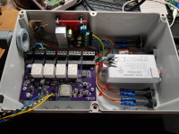
The hardware is also starting to take shape. I mounted the board in the IP67 enclosure. I ordered a buck+boost converter plus a switching AC/DC power supply. The buck+boost converter combo is used to later power the device by solar (+ battery backup), which varies widely in the input voltage, i.e. it can be below or over the needed voltage of the connected pump (approximatly 14VDC).
All the components have now been properly mounted within the enclosure, including fuses on the primary (mains) side and both secondary power rails.
The image shows all components mounted within the IP67 enclosure. Only the connection to the pump and the water reservoir sensor is missing. (147kb)
mwick83 7 years ago
I haven't tested the UART connections yet, but that's what I plan to to next (hardware-wise).
The software is also starting to take shape:
The configuration of the WiFi and other services is currently hardcoded in the file include/networkConfig.h. The repository contains a template version of the file. I'm planning to change the configuration mechanism either by providing console commands or by implementing a webserver.
This is the main PCB of the Irrigation Controller (135kb)