

The L-Board: T-Board Reimagined
I am a great admirer of the Elektor T-Boards, but the compromise these require has always bothered me. The long bar of the ‘T’ has to be kept as narrow as possible making for a difficult board layout. It inevitably ends up substantially wider than the 10mm ideal occluding a large proportion of the breadboard contact points.
Discussion (2 comments)

JohnHind 9 years ago
I placed the horizontal PCB under the insulator member of the pin header because in an earlier iteration a right-angle two-row pin-header was proposed soldered to the vertical board with conventional through-holes. This configuration may still be preferred although it makes for a more congested PCB.
However, using the straight pin-header, it may be simpler to invert the horizontal PCB and place it above the insulators on the pin headers both sides.
Another variation using the straight pin-header is to fit a two-row pin socket on the lower edge of the vertical PCB making it detachable.
JohnHind 9 years ago
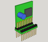
I call this structure an L-Board. It uses a two-row pin header on one side of a 10mm wide horizontal PCB and a single row header on the other. The pins on the inner row of the two-row header are trimmed flush with the bottom of the PCB which connects it to the adjacent pin on the single-row header. This assembly spans the gutter of a breadboard without occluding any contact points. It is the same design for all L-Boards and can be made in any length, using a low-cost single-sided volume produced PCB, and cut to length as needed.
The application specific circuit board must be double-sided and 1.8mm thick, which conveniently is the most common double-sided PCB stock used by pooling services. This board sits between the two rows of pins on the top side of the two-row header and has pads on both sides which are soldered directly to the pins. The board can be any height as necessary to accommodate the components and can have connectors, switches and indicators along the top edge.
As well as avoiding occlusion of contacts across the width of the breadboard, L-Boards are stackable without gaps along the full length of the breadboard gutter. Contrast this with the T-Boards which have to be mounted near one end of the breadboard since the short leg of the T will occlude any contacts under it.
Updates from the author
JohnHind 8 years ago
pcb4009top.png (414kb)
pcb4009bot.png (346kb)
PCB Gerbers (19kb)
PCB DesignSpark Project (36kb)
JohnHind 8 years ago
For information, V-Cut means that a grove is milled part way through the board on the top and on the bottom leaving a thin shim of material joining the boards. After pick-and-place assembly, the board parts can be snapped appart cleanly by hand.
Bottom view of PCB (174kb)
PCB Manufacturing Plots (21kb)
PCB Design Files (DesignSpark PCB) (49kb)
JohnHind 8 years ago
The schematic for the LV8548 section is direct from the datasheet with the simple inclusion of the recommended 10uF bypass capacitor.
The CYBLE-224116-01 section includes the recommended suppression inductors (the best option of separate inductors for each of the three supplies) and the optional VREF bandgap bypass capacitor (1uF) which may be omitted if not required. One of the strengths of the PSoC chips is a very wide power supply span (all the way from 1.71V to 5.5V), but this is compromised in this module by the narrower span of the RF Amplifier which provides the extended radio range. This chip may be disabled for standard Bluetooth 5 power, but if enabled the radio supply voltage must be between 2V and 3.6V. To mitigate this restriction provision is made for a low drop-out regulator to power the RF amplifier at 3.3V from input voltages above 3.5V (the specified dropout is 178mV, but assume 200mV to allow some headroom). I'm not sure how the regulator will behave in dropout: if the output simply follows the input with minimal losses then it may be acceptable to leave the regulator in circuit for the full voltage range. But provision has been made to replace the regulator with a link if necessary. Finally, the debug/programming signals are brought out on a 2mm pitch pin-header for easy connection to a CHIPKIT USB bridge broken off a low-cost Cypress prototyping kit.
When I discussed this design with Eurocircuits, they suggested using V-Cuts instead of the break-routed design shown. This might be a better solution if available as it would make the boards a little smaller and would simplify final assembly. An assembly frame will probably be necessary for pick-and-place (pretty much essential for the PSoC module) but it will probably be optimal to panelise multiple iterations in the same frame and V-Cuts could be used between the iterations and inside the frame as well.
Final assembly involves breaking the board parts off and cutting the gutter-strip to length. Then insert and solder a pin-strip into the middle row of gutter-strip holes. Trim these pins off flush with the board underneath. Now insert pin strips in the other two rows and solder. The pins on the far side of the gutter may be trimmed off above the board if desired. Finally, the carrier board is stood up between the two closest rows of pins and the pins soldered to the lands front and back. The long pins under the gutter-board are then positioned correctly to span the gutter of a standard breadboard without wasting any contact points.
PCB Bottom View (254kb)
PCB CAD Files - DesignSpark PCB (49kb)
PCB Manufacturing Files (22kb)
Schematic for PCB Design (115kb)
ClemensValens 8 years ago
That is looking pretty neat, well done. Regarding the panelisation, why not make three panels, one for each board?
JohnHind 8 years ago
Actually a Eurocircuits engineer suggested a better solution (if available) - V-Cut. I have posted a revised version designed for this.
JohnHind 8 years ago
1. Cypress CYBLE-224116-01. This is a PSoC (Programmable System on a Chip) combined with a RF power amplifier supporting Bluetooth Low Energy (BLE) 4.2 with extended range (up to 400 metres). In addition to BLE, the main chip in this module is an ARM M0 32-bit processor core with an extensive analogue and digital peripheral set. It should be noted that this module is brand new and is only available in samples at the time of writing. If necessary it can be substituted with an earlier model dropping back to Bluetooth 4.1 and, if unavoidable, also dropping the extended range capability.
2. LV8548MC. This is a beautifully minimalistic driver chip with only ten pins capable of driving four outputs from a wide input voltage range. It can be used to drive two small DC motors with direction control, or a single stepper motor or four separate solid state switches for relays or simple level shifting.
The proposed L-Board kit is intended to complement one of the Elektor Sensor Kits to provide a full breadboard-based educational experience in robotics or IoT. Even without using the BLE capability, the PSoC module provides everything needed to interface with practically any sensor including op-amps, ADC and current DAC for biasing as well as digital peripherals for I2C and SPI and the ability to create new digital peripherals using programmable logic. In contrast to some competing BLE implementations such as the Laird module familiar from earlier Elektor articles, the PSoC module makes it relatively easy to use BLE Profiles and to create your own Custom Profile. This approach uses BLE in the manner intended by the specification rather than via a generic serial port emulation profile and ad-hoc application protocol. The module can be configured for the full range of BLE roles meaning that two (or more) modules can communicate with each other without requiring a PC, tablet or phone as client.
Cypress produce a large range of very economically priced development boards for their PSoC chips. Most of these are breadboard friendly, but suffer from the occlusion problem that was the motivation for the development of the L-Board format. However it is difficult to compete with Cypress's subsidised prices. The PSoC BLE modules are a notable exception and are not available on breadboard friendly PCBs. The module itself is practically impossible to solder without access to a professional PCB assembly facility. The author has already had an application specific board design professionally manufactured using this type of module (by Newbury Electronics).
Cypress's CY8CKIT-145-40XX kit is particularly good value at around 12 GBP. For this ridiculously low price you get a full USB programmer/debugger based on a PSoC M4 ARM processor, a PSoC M0 target chip and a PRoC BLE module as an additional target. The board also includes break-off capacitive touch panels with LED indicators. It actually costs less than the three ARM chips purchased singly! However the PRoC (Programmable Radio on a Chip) is much cut down from the PSoC versions lacking most of the interesting analogue and digital peripherals. The USB programmer/debugger can be broken off and used with any ARM based PSoC (or PRoC) and this is a very low cost way of purchasing a general purpose programmer/debugger for these chips and modules. Cypress offer the development software, PSoC Creator 4.0, for free. Sadly this is Windows only and uses C rather than a more modern object oriented language such as C++, but it does feature extensive automatic code generation from graphical schematics and dialogs. The entry cost for ARM-based PSoC and PRoC development is therefore very low financially and quite reasonable intellectually.
The LV8548MC from On Semiconductor will open up the world of robotics by providing an actuation interface to go with the sensors. Compared to other motor driver chips, this chip is beautifully simple and versatile allowing it to be re-purposed for practically any modest current drive requirement. It does not need a logic supply, only load supply voltage, ground, four inputs and four outputs. The inputs accept a wide range of voltages 1.8 to 5.5 volts which covers the entire range of the PSoC and all digital chips in common use. With all its inputs below 0.7 volts (or open circuit), the chip turns off and consumes virtually no power. The outputs can be operated at 4 to 16 volts and each can drive up to 1A. They can source as well as sink current and go open circuit (however the drivers are arranged in pairs and you cannot have both outputs in the pair pulling high simultaneously, or one off with the other on). The chip can drive two DC motors bidirectionally (full bridge) with freewheeling and active breaking and speed control if the inputs are driven with a PWM signal. Alternatively it can drive a single stepper motor with appropriate input sequencing. The PSoC module is capable of providing these PWM or stepper waveforms using dedicated digital peripherals. Finally the outputs can be used individually as switches to control inductive or resistive loads or perform logic level shifting (from 3.3V to 5V).
http://www.cypress.com/file/331006/download
http://www.mouser.3dco.uk/ProductDetail/Cypress-Semiconductor/CY8CKIT-145-40xx/?qs=2mW%252bF1zkL3gCnQtA7gYuXw%3d%
http://www.onsemi.com/pub_link/Collateral/LV8548MC-D.PDF
ClemensValens 8 years ago
This sounds very interesting indeed, nice chips. However, I am not sure if I understand it completely. You mention a three-part pcb, but only two components. Is the gutter strip the third part? Then what is a gutter strip? A horizontal board with pins on both sides of the breadboard gutter? The two other boards are plugged vertically on the gutter strip, is that it?
Are you also going to write software for the PSoC?
REgards,
Clemens
JohnHind 8 years ago
I have software written for another project (separate code for a PRoC module and for a PSoC non-BLE chip) which could be readily adapted. Also Xamarin client code for Android. Covering this properly in print would be a much longer article, but a simple example could be posted on line and maybe consider a follow-up article covering in more detail later?
Cypress also have a lot of example code online:
http://www.cypress.com/blog/100-projects-100-days