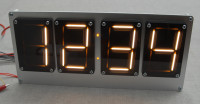
LEDitron display [150448]

LED bulbs with LED "filaments" are becoming increasingly popular. These filaments consist of a glass strip with a large number of small blue LEDs wired in series deposited on them. This assembly is coated with a yellow phosphor which converts the blue light emitted by the LEDs into white light with a spectrum resembling that of an incandescent bulb.
LED bulbs with LED "filaments" are becoming increasingly popular. These filaments consist of a glass strip with a large number of small blue LEDs wired in series deposited on them. This assembly is coated with a yellow phosphor which converts the blue light emitted by the LEDs into white light with a spectrum resembling that of an incandescent bulb.
These "filaments" are now also on sale on eBay for very low prices as a component for DIY purposes. As such I decided to try to make a 7 segment display with them.
Everyone who is into vintage electronics probably knows about numitron tubes. These are in fact an early (1970's) display type consisting of a glass tube with 7 incandescent filaments arranged in a typical 7 segment configuration. You simply pass current through the filaments you want to be lit up, and they literally light up exactly like a light bulb.
Unfortunately, most of these numitrons are quite small so I decided to make a larger one using the LED filaments from eBay. The display in the picture measures 8x11 cm and was made of laser cut acrylic, but you can use other materials as well. The front which is now made of transparent acrylic can also be replaced by colored acrylic which will act as a filter.
To power these LED filaments, a small step up converter based on a 555 which steps up the voltage to around 50-70V, will work just fine. For driving the segments, MPSA42 and MPSA92 transistors will be suitable. These are cheap and suitable for higher voltages.
I included a schematic for a circuit which will drive 2 displays using multiplexing. The circuit is based on a previous design I made for driving IN-9 tubes. The output voltage should be adjusted for +/- 70V so that the average current through the filaments is 3 to 4 mA. More current is possible, but then the filaments will be too bright for this application.
I finally got the time to design a PCB for this project. As the first tests were successful I'll make a video of a few of these displays within a few days.
The current design allows controlling 2 displays using multiplexing but it can easily be expanded to drive more displays. As the power supply easily can deliver more than 100mA it should be possible to drive 4 or even more displays. For the electrolytic capacitors we used Nichicon capacitors with a very low ESR.
In the meantime we modified the mechanical design as we had some issues connecting the LED filaments when using the first design. We now use turned pin contacts to connect the filaments which also allowed the make the display unit more compact. You will find the new CAD files attached with this project. The new design also provides a 3mm hole for a 3mm LED in case you wish to have a decimal point.
A video of the test setup is here: https://vimeo.com/130684970 Note that the flickering in the video is due to interference between the multiplexing frequency of the display and the camera's shutter speed. As our goal is to drive 4 displays eventually, the display is on 25% of the time. In real life there is no flickering. Driving voltage is around 80V and the display is clearly visible even under sunlight conditions. When using an Arduino, the sketches for our IV-3 project can be reused to drive these displays.
A new video of a test setup with 4 displays is available on Vimeo: https://vimeo.com/135479489
The circuit is running at 85 V and everything stays relatively cool with 4 displays as load. Only the inductor warms up a little to approximately 45 °C. The refresh rate is now twice the refresh rate of the IV-3 project, otherwise some flickering was noticeable.


Discussion (6 comments)