A GPS Tracker that uses the LoRa network to transmit its position. Data will be processed with NodeRed and stored in a database.
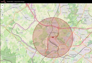
After the LoRa-Node has been first used in the LoRa-Switch this is the second project where this is used as core for an application. The LoRa-Node combines a MCU , LoRa-Module and the reqiered components for the battery on one PCB that can be programmed with the Arduino-IDE and the STM32duino as with the STM32CubeIDE. To get software to the chip you can use a USB to Serial converter and some jumper wires. As the bootloader is included in the chip as ROM you even don't lose any space for your software and you can't accidentally overwrite the bootloader. But most of the features have already been told. This shall now focus on the use as LoRa-Tracker. In the end will will show a Node-Red setup that can generate maps like this in a browser window:
The ingredients you need, and also you can find on other commercial tracking devices:
MCU, here we use a STM32F072 ( 64kb Flash, 16kB Ram )
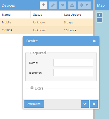
Fimrware 1.6 has been released with CayenneLPP support for data transmission. Also while a Node-Red flow for tracking may be a good start, more can be done. By using Traccar and a small Node-Red flow for data Conversation you can get even better tracking with free to use software. For this to work install Traccar onto a linux powered device like a Raspberry Pi by getting the software at [https://www.traccar.org/download/] and following the installation instructions at https://www.traccar.org/linux/ . After the setup is compleate you shall be able to connect to Traccar using the IP of it with port 8082 .e.g. http://127.0.0.1:8082 . You need to add a Tracking device
You can choose as name what you like. The identifier will be important as this needs to match the one inside the Node-Red flow we will show later. We use "TK103A" as an example here. Confirm your settings and a new Device will show up.
It won't be shown as online now, now you need to import the Node-Red flow and add a few parameter. Setup your TTN Account so you can receive Data form the Application you created inside TTN.
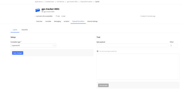
Update the LoRa GPS Tracker to the latest Firmware Version and use CyanneLPP for Data transport. Make sure your Device within the TTN has the same device name as choosen inside Traccar. For the TTN make sure you have the Payload decodung set up propperly, and name your device TK103A.
The next step is to import an configure the Node-Red flow. You can grab a copy in the Dowloads of this page.
This will forward TTN Messages from the LoRa GPS Tracker to Traccar.
Assembly
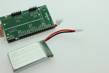
As energy source you can use AAA lithium batteries ( 10440 type ) or you can use lithium packs that are normally used in drones. These come 5 pieces with charger for less than 20 bucks and offer 720mAh. The drawback is that you need to attach a connector, suitable for the battery. Molex types are most common to find ( 51005 Molex connector ) the counterpart is less often to find on warehouses starting with an “A”, but common cell on flight models as spare parts. So may have a look at a model shop nearby. If you get cells with JST connectors this makes it really easy as you can find more often the prebuild cables online. Also note that it can be beneficial to solder the wires on the top for later easy access to disconnect the cell form the main pcb Fitted with the connector the LoRa-Node now looks like this
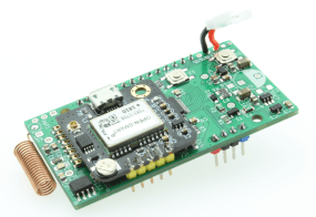
Next step will be the placement of the GPS module. This needs to be connected straight over the LoRa-Node pcb.
Flying circuits
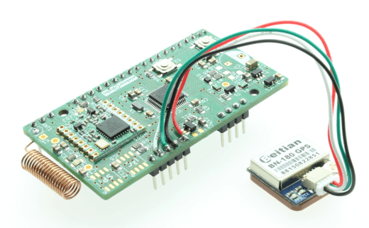
This will work well if you use the rechargeable batteries for drones. If you are going to use AAA lithium rechargeable batteries this will make it not fit inside the Hammond 1551 enclosure. You can use a Beitian BN-180 GPS module instead. This module must be placed in transparent heat shrink tape to avoid shorts on the batteries
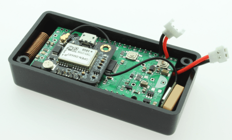
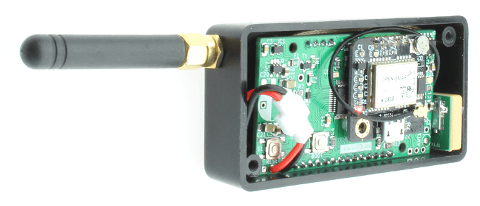
If you squeeze everything in a box the result will look like this
This will be a tight fit for the components a be warned, even if the coil antenna looks nice and small, the radiated power is not as much as with a straight peace of wire. To give some figures, you will lose about 30dBm in this placement compared to a straight wire antenna. This will be a huge difference and reduce the range from 1km down to less than 10 meter. This means an external antenna is highly recommended to good transmission performance. The GPS antenna works decent and will get the job done. An active one with a 28db LNA integrated will help the module to acquire a position faster an can, even that it is using some power, lead to a longer runtime. If you intend to use an external antenna, the whole setup will look like this:
Power usage and estimated runtime
When it comes to power usage, you will often find the low µA values for standby. And while we get 150µAh for sleep, powering the mcu ram and have power losses across all components, this is not the worst part. With that we will get form a 720mAh cell, assuming we can get 600mAh out of it, about 4000 hours standby, in theory ( 166 days , so more than half a year). The worst part is the time while the GPS module is working, adding 55mAh to 60mAh to the power consumption. Also the MCU will take 2mAh to 3mAh as well as the short time where the LoRa module will take 100mAh max for transmit. While the transmitter is less than a second, the main amount of power is drawn from the GPS module.
As the lab has really poor reception conditions, a kind of worst case test, the receiver will take up to 10 minutes for a cold start and about 2 to 3 minutes for a hot start. Cold start means that the receiver has no valid information left in his memory about the GPS satellites needed for position calculation and a hot start means that some or even all information are still valid. This leads to an average of four minutes runtime for each position we need to get, and this is what will primarily affect the runtime.
Keeping that in mind the interval used to determine the position will heavy give the amount of runtime we can get out of the battery. There are some ways to get a bit extended runtime. One is the use of an active antenna, that will draw may 5-7mA additional but reduce the time for a position. Another option is to use a bigger enclosure and a battery that will give a higher capacity.
is:
Inside the Software
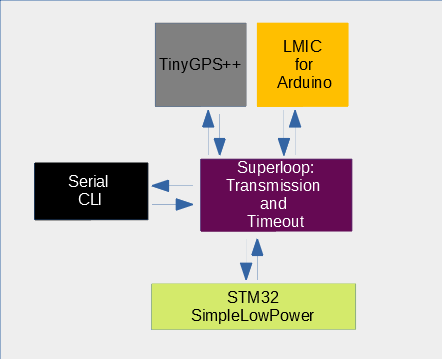
The software itself is done with the Arduino framework for the STM32. This allows to most of the Arduino libraries you already know for the STM32 and give use access to the TinyGPS++ and the LMIC for Arduino, two components that will be the main core for the software itself. Some other libraries are also included to get everything working. The main disadvantage of using the Arduino framework is the amount of code space used in the end. While having 64kB the firmware will eat up 89% of it, so the room for more features is limited with the current mcu if the Arduino framework is used. Besides this we will have a short look on what modules are inside the software:
We a basic super loop that moves data from the GPS UART to the TinyGPS++. From the TinyGPS++ the current GPS state i polled, and if a valid position is detected, send via the LMIC to the LoRaWAN.
If a certain amount of time has passed, the software will disable the GPS module and send a message with no valid GPS position. After one of these two events the STM will have the GPS disabled by cutting power and enter for a given time the sleepmode. So far this is very easy, but what dose the CLI and why have we no numbers here for the timespans used?
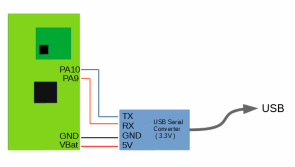
Well within the CLI, that can be access by a USB-Serial Converter, you can setup the parameter. This is the same connection that is used also for the firmware upload to the mcu.
So you can open a terminal software of your choice, like putty or the Arduino serial monitor and start configuring the device
So you can configure the device with the information you get from e.g. The Things Network. For an easy start use APB mode and enter the required credentials. These are the NWKSKEY, APPSKEY and DEVADDR. To set the Device into APB mode just use "set ACME APB". This is basically all it needs, the data rate will be as default SF7BW125, fastest mode, shortest range. You can change this with "set datarate SF9" to use SF9. The rates of SF12 and 11 are not supported as this will void the rules of the TTN for statically configured devices.
All transmissions here will be without any acknowledge form the LoRaWAN ( TTN ). Two things that will have influence of your battery runtime are the GPSTIMEOUT ( default 10 minutes ) , the time that the system will wait to get an valid GPS position, and the interval used to transmit the position ( default 15 minutes ).
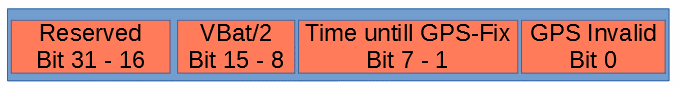
The device will transmit the data as a set of bytes to the TTN, the payload has the following format:
The status currently only indicates if the position is valid or not. This format is not ideal but working, as we use some bytes more than needed with a better data coding. In the four status bytes we have encoded some additional information
This can later help to deterime the power used for the current tracking and also give a forcast how long the cells will last.
The setup is working now and if we are in range of a TTN Gateway new data should arrive. The included Node-Red Workspace will be able to grab the data form the node, write it to log files and show the data on a map in a webbrowser window.
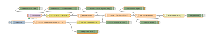
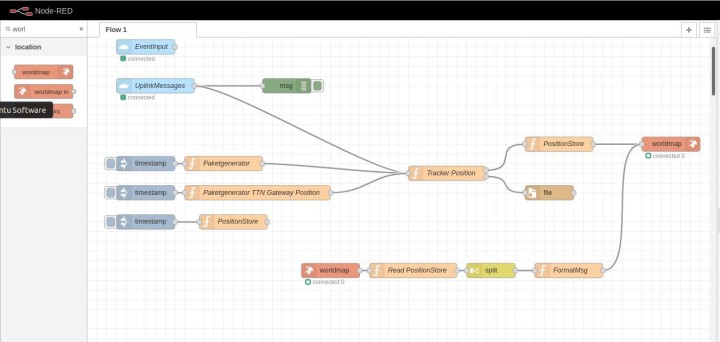
We assume that you are familar with the Node-Red setup. You need to have the following nodes installed:
If this is all in place you can impot the atached JSON file and should get a workspace like this:
Be aware that you need to enter you ceredentials into the UplinkMessages Node. For that all information can be aquired form the TTN Console, and everything should be good to go.
Login
No account yet?Register for free!
Forgot password?
Please enter your email address. Instructions for resetting the password will be emailed to you now.


Discussion (3 comments)
HaSch 2 years ago
The project still doesn't work as it should. After switching to Traccar, adjustments were still required, which are still open. Data doesn't end up at Traccar and that's very bad. In return, the data ends up twice in TTS V3, which is also not good. To remind the open issues:
Data does not arrive in Traccar.
Data arrive twice in the TTS V3.
Data should be stored as CSV on the Raspberry Pi local.
It would be great if the project could finally be completed.
German version:
Leider funktioniert das Projekt immer noch nicht, wie es soll. Nach der Umstellung auf Traccar waren noch Anpassungen erforderlich, die immer noch offen sind. So landen die Daten nicht bei Traccar und das ist ja nicht Sinn der Sache. Dafür landen die Daten doppelt in TTS V3, auch nicht gut. Um die offenen Punkte in Erinnerung zu bringen:
Daten kommen nicht in Traccar an.
Daten treffen doppelt im TTS V3 ein.
Daten sollten als CSV auf dem Raspberry Pi lokal abgelegt werden.
Es wäre großartig wenn das Projekt endlich abgeschlossen werden könnte.
EN0175803ID 3 years ago
Does anybody has the stl files for the housing?
Mathias_Claussen(Elektor) 3 years ago
Best Regards
Mathias Claußen
HaSch 4 years ago
This is a fascinating project that leaves plenty of room for your own modifications. For example, I have integrated a charging circuit for a battery that can be ordered for little money in China, e.g. this one here. They are mostly based on the IC TP4056 and deliver 1A charging current. Since this is usually too much for a small lithium-ion battery, you have to modify the small board and this is how it works: You have to identify the resistor that is connected to pin 2 of the IC and has a standard value of 1k2. The charging current should have about half the battery capacity in mA. Since my battery has 500mAh, I can charge it with 250mA. To do this, the SMD resistor on the board must be exchanged for a resistor of around 5k. If you do not do this and charge the battery with 1A, you risk the death of the protective circuit built into the battery. In battery operation, it is always useful to have a switch that disconnects the battery from the board when the tracker is not needed, no matter how little energy it needs. If you install the tracker in a housing for which the circuit board is intended, you can no longer see the LEDs without further take action. Here a few pieces of transparent filament help as light guides that make the LEDs visible from the outside. In my making out there are three on the front for the green and red LED of the LoRa board and for the red LED of the GPS module, as well as two on the top to be able to observe the status of the battery charge. There are big differences in quality when it comes to GPS antennas. If the GPS module does not achieve a fix within a reasonable period of time, you should try a different antenna. I used an antenna that still works inside the case.
Deutsche Version:
Das ist ein faszinierendes Projekt, das viel Raum für eigene Modifikationen lässt. Ich habe zum Beispiel ein Lademodul für einen Akku integriert, wie man es für kleines Geld in China bestellen kann z.B. dieses hier. Die Module basieren meist auf dem IC TP4056 und liefern 1A Ladestrom. Da das für einen kleinen Lithium-Ionen Akku meist zu viel ist, muss man das kleine Board modifizieren und das geht so: Man identifiziert den Widerstand, der mit Pin 2 des ICs verbunden ist und standardmäßig einen Wert von 1k2 hat. Der Ladestrom soll etwa die Hälfte der Batteriekapazität in mA haben. Da mein Akku 500mAh hat, kann ich ihn mit 250mA laden. Dazu muss der SMD-Widerstand auf dem Board gegen einen Widerstand von etwa 5k ausgetauscht werden. Macht man das nicht und lädt den Akku mit 1A, riskiert man den Tod der in den Akku eingebauten Schutzschaltung. Im Batteriebetrieb ist immer auch ein Schalter sinnvoll, der den Akku vom Board trennt, wenn der Tracker nicht benötigt wird, ganz gleich wie wenig Energie er benötigt. Baut man den Tracker in ein Gehäuse ein, für das die Platine ja vorgesehen ist, hat man ohne weitere Maßnahmen keinen Blick mehr auf die LEDs. Hier helfen einige Stücke transparentes Filament als Lichtleiter, die die LEDs von außen sichtbar machen. In meinem Exemplar sind das drei an der Front für die grüne und rote LED des LoRa-Boards und für die rote LED des GPS-Moduls, sowie zwei an der Oberseite, um den Status der Akkuladung beobachten zu können. Bei den GPS-Antennen gibt es große Qualitätsunterschiede. Erreicht das GPS-Modul in einem überschaubaren Zeitraum keinen Fix, sollte man eine andere Antenne ausprobieren. Ich habe eine Antenne verwendet, die auch innerhalb des Gehäuses noch funktioniert.
img-2164.jpg (495kb)
img-2163.jpg (383kb)
img-2165.jpg (688kb)
img-2166.jpg (617kb)
img-2168.jpg (785kb)
img-2169.jpg (731kb)