
Mastering Distortion, Example for Audio Amplifiers
Amplifying components like transistors, tubes, or Field-Effect Transistors (FETs) are inherently nonlinear. This makes the design of high-quality linear amplifiers both complex and costly. An alternative approach to achieving overall linearity, without relying on extra amplification stages or extensive feedback, involves using a feedforward system to compensate for distortion.
A practical example of building a system to linearize distortion in an audio amplifier.
The human auditory system is highly sensitive to distinct tones, making it exceptionally capable of detecting even the slightest distortions in sound. This sensitivity is especially critical in audio applications, where minor imperfections can be easily perceived. Therefore, having a high-quality, linear audio amplifier is essential for accurate sound reproduction and maintaining audio fidelity.
The human auditory system is highly sensitive to distinct tones, making it exceptionally capable of detecting even the slightest distortions in sound. This sensitivity is especially critical in audio applications, where minor imperfections can be easily perceived. Therefore, having a high-quality, linear audio amplifier is essential for accurate sound reproduction and maintaining audio fidelity.
However, creating a truly linear amplifier poses significant challenges. Amplifying components like transistors, tubes, or Field-Effect Transistors (FETs) are inherently nonlinear, meaning that the output signal is not a perfect, scaled-up version of the input, leading to potential distortion. To mitigate this, feedback techniques are often employed to improve linearity. While effective in reducing distortion, feedback loops also decrease the amplifier's overall gain. Consequently, additional amplification stages are typically required to achieve the desired level of signal amplification while maintaining linearity. This makes the design of high-quality linear amplifiers both complex and costly, especially in high-fidelity audio systems.
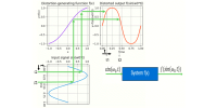
An alternative approach to achieving overall linearity, without relying on extra amplification stages or extensive feedback, involves using a feedforward system to compensate for distortion. Instead of adding more stages or increasing feedback, this method accurately measures the distortion-generating function, f(x) , inherent in the amplifier. A compensating function, g(x), is then applied to the signal before it enters the amplifier. This compensating function is designed to counteract the specific distortions produced by the amplifier.
By first processing the signal through g(x), and then passing it through the amplifier with its distortion function f(x), the system achieves a linear output, leveraging the mathematical property that f(g(x))=x . This approach can reduce the need for additional amplification stages and extensive feedback, potentially lowering costs while still ensuring high linearity in the overall system. However, it requires precise measurement and compensation, often implemented digitally, to ensure accurate distortion correction.
Results
Results
The overall distortion for a full-scale signal improved significantly from an initial Total Harmonic Distortion (THD) of 10.95% on the distorted signal f(sin(w0*t)) to a remarkably low THD of 0.0066% on the fully compensated output signal f(g(sin(w0*t))).
For demonstration purposes, an exaggerated level of distortion was applied to the Distortion Generating Function f(x), resulting in a THD of 10.95%. Using a Least Mean Squares (LMS) curve fitting technique, the compensating function g(x) was successfully estimated, reducing the overall compensated distortion level to a THD of 0.0066%.
Further improvements in reducing distortion are possible by employing more advanced methods to refine the estimation of the compensating function g(x).
With increased computational effort in determining the compensating function g(x), the Total Harmonic Distortion (THD) was further reduced from 10.95% to as low as 0.0000085%.
Note: when looking in Mastering_Distortion_Audio_Example001.pdf you could also have a look into chapter 6 first :-)
By SigMul, aug 2024.
Discussion (0 comments)