The Summer Circuits 2022 contained a circuit suggestion that I adapted to my ideas and my tinkering box
I have often wanted to be able to measure very small resistors or BLDC motors properly. When I looked in my tinkering box, I found most of the important components for this project.
However, I allowed myself a few deviations. For example, I still had a 6 volt power supply unit which I liked better than a battery or rechargeable battery power supply. These are usually empty exactly when you need the device. I also wanted to save myself the expense of a ready-made, expensive DC voltage converter for the potential-free supply of the digital voltmeter; I had already built something similar in the past. This somehow took me longer than I thought, but in the end my experiment with a DIY transformer made from a small shell core worked.
I also didn't want to buy the selector switch as I still had a similar part from a printer switch. However, it only had two positions and it was a mental exercise to extend it to 4 stages. Looking at the sensitive contacts of the switch made me doubt whether the selector switch could really withstand the measuring current of up to 1 ampere in the long term and might not cause a significant error or even "smoke out". So I switch the current with three relays, which also makes the wiring easier.
The power supply works with two secondary windings and two-way rectification, so I was able to obtain the 24V for the relays from the transformer. The backlight of the digital voltmeter, which needed more than the stabilised 6 volts, could also be activated as a "switch-on control".
It also took me a little time to recognise the traps that Elektor had probably included in the circuit diagram. The resistance values for 1mA current are quite wrong, and you also have to look at the data sheet for the LM317 to be able to make the correct wiring.
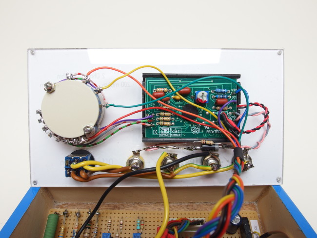
The back of the front panel. Thanks to the relays, the tangle of cables could be kept to a bearable level.
In Elektor, special test leads are recommended to eliminate the resistance of the cables. However, the problem of contact resistance remains with this suggestion. I have simply installed two more sockets and can work with four cables. This means that the voltage to be measured across the device under test is independent of the resistance of the cables carrying the measuring current and the contact resistance of the terminals. However, as this is not always necessary, I can connect the sockets with a switch and then also work with two normal cables.
I have broken new ground for the first time in the construction of the housing. I have little trouble building an enclosure from a few plywood boards. The problem is rather to create an attractive surface. So I came up with the idea of ironing a hot-glue-coated film from model aircraft construction onto the raw plywood surface. This quickly resulted in an attractive and sufficiently hard-wearing exterior for the device. I also always have difficulties with the front panels and their labelling. I drew the texts for the controls on the computer and printed them out. The paper is now simply clamped between two thin panes of plastic glass.
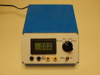
I think the result looks well. Literally, but above all technically. After adjusting the current sources with the trim pots or by connecting fixed resistors in parallel, I have a sufficiently accurate measuring device for small resistors.
As my English skills are still in need of improvement, I have translated this text with "deepl.com".
Login
No account yet?Register for free!
Forgot password?
Please enter your email address. Instructions for resetting the password will be emailed to you now.


Discussion (3 comments)
Inch-o 1 year ago
With 1A max current the 317 is a bit at its limit... Maybe look after the LT1085 which is declared at 3A, still being housed in a TO220 casing.
As said, a very nice and useful gadget to have at hand, also for checking resistance of cables/wires, used in harsh working conditions, which can be corroded and possibly are not easily accessible for visual inspection!
The enclosure is very nice. At first sight it looks very professional!
When FR4 PCB material was still available in quantities, I used to make the enclosures out of it...
Excellent electrical noise shielding... ;)
PicoPete 1 year ago
Not to seem negative, the project explanation is OK as far as it goes but there are a number of things that should be clarified IMO (In My Opinion) including some explanation about testing and calibrating the device.
First, the schematic for the project is somewhat odd-looking, at least to me as I am used to seeing more "traditional" symbols. So I don't know if this is a result of the authors particular schematic progam used or the schematic program Elektor uses.
Second, the author states that there's is an error as a result of "Elektor Traps" (what are Elektor Traps?) and says: "It also took me a little time to recognise the traps that Elektor had probably included in the circuit diagram. The resistance values for 1mA current are quite wrong, and you also have to look at the data sheet for the LM317 to be able to make the correct wiring. " Specifically...
"The resistance values for 1mA current are quite wrong, and you also have to look at the data sheet for the LM317 to be able to make the correct wiring."
So what are the correct values for the 1ma resistance (and which resistors are we refering to?), and why the need to look at the datasheet for the LM317 for "the correct wiring:??? Why isn't the schematic correct to begin with. If the schematic is wrong then why publish an incorrect schematic?
Third, regardless of any error which may be corrected later, the device needs to be "calibrated" or tested to ensure it functions as expected, so why aren't there any suggestions or instructions on calibration?
Forth, what are the tolorences of the resisors, wattage ratings (I see what looks like 1 or 2 watt resistors) and TCO ?
Fifth, It would be nice to see a BOM with part sourcing and tolerance and TCO if applicable.
Sixth, what are the specifications of the device overall, i.e. what's the minimum resistance it can accurately read, error, etc?
Seventh, it would be nice to include an example of measuring a number of small-value resistances and explain things.
I don't want to seem picky and it looks like a really interesting project, but consider that someone with little experience might decide to build this device and a little more information might make the difference between success and failure.
I look forward to a corrected schematic that spells out the correct resistances and tolerances and that identify any "critical" parts.
Lutz Kather 1 year ago
the resistance value for 1mA is indeed wrong, 1250 Ohm if the LM317 has no tolerance would be correct
However, as this has a tolerance, it must be adjustable in this range, including taking into account the resistance tolerance of 1%, I would provide a 5% adjustment range for the resistance value here, i.e. 1250 Ohm +/- 5%, resulting in 1187 Ohm to 1313 Ohm.
The actual setting range with the circuit diagram values is 279 Ohm to 1345 Ohm, so the usable range of the potentiometer is only approx. 10% and the setting is more difficult than necessary.
With the E12 series you could set the value from 1100 to 1443 ohms with R6=R7=2.2k and a potentiometer with 2K and would use 33% of the setting range
With values from the E24-E48 series or by connecting E12 fixed resistors in series, you could even use 91% of the setting range with R6=2K R7=2.9K and a potentiometer of 1K, which would be a good dimensioning.
The same applies to 9mA, only 17% of the setting range is used, instead of R9 and R12 = 100 Ohm and R10 = 100 Ohm and potentiometer 500 Ohm, it would be better to select R9 and R12 = 120 Ohm, R10 = 270 and potentiometer = 100 Ohm, so that 75% of the potentiometer's setting range is used.
for 99mA R13 R15 = 6.5 Ohm (???) and R14 330 Ohm are also not a good choice, the target would be a resistance of 12.62 Ohm at 1.25V and 99mA, so 12.5 is achieved, which is only 1% nominal deviation, which is not a real problem at 5% error, but what speaks against choosing R13 and R15 = 6.8 Ohm (E12) and R14 = 180 Ohm, so you only have 0.15% nominal deviation.
The question arises as to why a calibration option has been omitted here
Up to this point, the power dissipation is less than 70mW and can be covered well with metal film resistors, which in principle can be 5-10 times higher, with measuring devices you should not go to the limits of the power dissipation due to self-heating, factor 5-10 is a good value to stay below.
However, the 999mA is not a good solution at all, firstly because the nominal value deviates by 1.9% and secondly because the 1.5 Ohm has a power loss of over 1W. You need an expensive measuring resistor, which quickly costs 20€ for 1% tolerance and 3W
You can connect several good metal film resistors with 0.6W in parallel, because of the power reserve I would connect 6 times 8.2 Ohm in parallel and additionally a 15 Ohm value, so you have approx. 0.1% nominal deviation.
With the non-calibratable currents, however, the 4% of the LM317 remains and the 1% for the resistors
I would therefore take a different approach in principle, I would set all currents with fixed resistors and rely on the printed values through suitable parallel/series connection, but choose 0.1% resistors, which are only twice as expensive and therefore ok
But then I would not adjust the current to 1mA, 10mA, 100mA and 1A but 4% higher because of the potential tolerance of the LM317
Before the voltage measurement, I would then place a voltage divider, with which you can reduce the voltage by up to 8%, in case the LM317 does not have 1.25V -4% but 1.25V +4% and my currents would also be nominally 4% too high, therefore 8%.
Then I would only have to trim once and would have each measuring range with max +/- 0.1% error, that would be my idea for the task
The wiring is not correct, there is no current path through these resistors that define the current.
If you use adjustable resistors 1% standard resistor are ok
This would also answer the question about power loss. A parts list would be useful, but what is easy to get for hobbyists in Germany can be a problem overseas, but of course a suggestion as a hint would be helpful.
Calibration instructions are an important point for inexperienced hobbyists, and this simple project is clearly aimed at this target group. This could be done with the help of several resistors with 0.1%, but it is important to have all measuring ranges and perhaps an Excel template where you can enter the measurement results with actual and target value for each range. That's how I do it professionally.
The project is interesting and your tips are all correct, I hope I was able to help a little with my comments.
Lutz Kather 1 year ago
BastlerRolf 1 year ago
The symbols for resistors and others are correct following European Standards.
Lutz Kather 1 year ago
The 1.25V reference is between OUT and ADJ, which results in the constant current for the DUT. According to the schematic, the current would not be limited by the resistors but by the current limit of the LM317 or the power supply, whichever is lower
Senior Editor, Elektor 1 year ago
Kind Regards.
Roberto Armani