

Mini alarm with radio remote control for electric bike
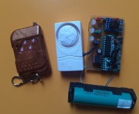
My son acquired a rather special electric bike... See img -> the-cycle :) It's all the rage in the area, so I suggested that we first equip it with a simple and unpretentious alarm, in order to warn it if the object moves. In the corner of a cupboard I had a few 433Mhz transmitters and receivers and a door alarm that had been given to me. These two products are easily found on the internet at low prices. I combined these products with an ATtiny85 and a tilt ball to create a remote control alarm system.
Combine an ATtiny85 with a hacked door alarm and a 433mhz 4 (or 2) button remote control, to build a cycle alarm.
We use :
- output D3 of the radio module for detection of the alarm mode in use
D3 radio module connected to PB4, pin 3 of the ATtiny.
- output D2 of the radio module for detection of stopped alarm mode
D2 radio module connected to PB3, pin 2 of the ATtiny.
- the VT output of the radio module for confirmation of one of the two messages
VT radio module connected to PB1, pin 6 of the ATtiny
When commissioning, through PB0, pin 5 of the ATtiny, we activate a transistor which acts as power ON. (beep beep)
Originally, when activated, my door alarm emits two tones.
When turned off, no tone, hence an LED to display the status of the alarm stopped
An OFF alarm info LED indicates the alarm status. Connected to PB2, pin 7 of the ATtiny.
Code : Mini_Alarm.ino in zip
NOTA : For the tests and my ears, I replaced the alarm buzzer with an LED
I integrated the whole thing into a 4-battery carrying box, stripped of its interior partitions
Some holes were made to release the sound of the siren
The door alarm is missing its base, its batteries and the I L S contactThe base served as a template for the effector with two holes on the battery holder box in order to screw the siren into it.
The green LED is stuck at the level of the switch removed from the battery box
Two wires for the 5v power supply come out of the closed battery box once equipped with the internal ATtiny 8Mhz duly programmed with the package_damellis
The alarm is installed in the electrical trunk where the motor drivers are located.
A power supply was found there, I connected the alarm to this power supply even after the bike ignition was turned off.
I inserted an HW 083 power shield to provide 5v
The tilt has been adjusted : Contact closed -> bike position on its stand.
I will not give you precise information about the installation, this being an alarm, but I am counting on you to adapt this project to your needs.
This alarm was produced urgently with the available components. A V2 model may see the light of day....
See Mini Alarm Sleep mode
//FR
On utilise :
- la sortie D3 du module radio pour la détection du mode alarme en service
D3 module radio connecté sur PB4, pin 3 de l'ATtiny.
- la sortie D2 du module radio pour la détection du mode alarme arrétée
D2 module radio connecté sur PB3, pin 2 de l'ATtiny.
- la sortie VT du module radio pour la confirmation d'un des deux messages
VT module radio connecté sur PB1, pin 6 de l'ATtiny
Lors de la mise en service, au travers PB0, pin 5 de l'ATtiny, on active un transistor qui fait office de power ON de l'alarme de porte (beep beep)
D'origine, à la mise en service, mon alarme de porte émet deux tonalitées.
A la mise à l'arret, aucune tonalitée, d'où une led pour visualiser l'état de l'alarme arrétée
Une led info alarme OFF, indique l'état de l'alarme. Connectée sur PB2, pin 7 de l'ATtiny.
Le code : Mini_Alarm.ino est dans le zip
Pour les tests et mes oreilles, j'ai remplacé le buzzer alarme par une led
J'ai intégré l'ensemble dans un boitier porte 4 piles, dépouillé de ses cloisons intérieurs
Quelques trou ont été fait pour libérer le son de la sirène
L'alarme de porte est déséquipé de son fond, de ses accu et du contact I L S
La base à servi de gabarit pour effecteur deux perçages sur le boitier porte pile afin d'y visser la sirène.
La led verte est collée au niveau de l'interrupteur déposé du boitier porte piles
Deux fils pour l'alimentation 5v sortent du boitier porte piles refermé une fois équipé de l'ATtiny 8Mhz interne dûment programmé avec le package_damellis
L'alarme est installée dans le coffre électrique ou se trouve le drivers moteur.
Une alimentation y a été trouvée, j'ai connecté l'alarme sur cette alimentation présente même après que le contact du vélo soit mis à l'arret.
J'ai intercallé un shield alimentation HW 083 pour fournir le 5V
Le tilt a été ajusté : Contact fermé -> position vélo sur sa béquille.
Je ne vous donnerai pas d'information précise de l'installation, celle-ci étant une alarme, mais je compte sur vous pour adapter ce projet à votre besoin.
cette alarme a été réalisé dans l'urgence avec les composants disponnible. Un modèle V2 verra peut-être le jour.......
Voir mise à jour Mini Alarm Sleep mode
Updates from the author
Arduino47 11 months ago
It is obvious that a good choice ATtinyXXXX could replace the ATtiny85 alarm and the ATtiny85 Tilt.
I made it with what (or those) I had on hand.
The alarm may need to be autonomous in terms of power supply, to place it elsewhere than on an electrical cycle, or, to not modify its wiring.
The tests being conclusive by powering the alarm using a type 18650 battery (3V7 1.8Ah) and in order to reduce the consumption of the whole in standby mode (alarm in Off state), I reviewedt he code.
The PB1 pin where VT radio is connected is configured to act in ISR PCINT0
The PB2 info LED becomes debugg LED. We will do a blink sequence before switching to sleep mode.
Measures :
Consumption in standby mode is approximately 2.15mA.
The alarm on without LED_ON 14.5mA,
with red LED_ON connected to the powerON 23.5mA
power supplyBattery voltage 4V08, Tiny Tilt voltage 3V37.
Shéma_Mini_Alarm_Tiny_Tilt_V3.pdf
Two LEDs have been added if necessary.Alarm LED ON (red), Tilt control LED (blue) for silent testing. The LED (green) was already in place in the original project.
Code: Mini_Alarm_V3.ino (in the zip)
What code do :
At startup, the LED connected to PB2 flashes before UC enters sleep mode. Only the radio is watching.
When a radio message arrives, receiver's VT causes an interrupt via PB1
Invalid message, we return to sleep mode.
Valid message, Bp_alarme_ON, we activate Tiny tilt and the door alarm via the power On transistor.
Original, the proto door alarm model emits two tones (Beep )) Beep ))) to inform.
Tiny Tilt (At85+GY61), records the position of the object. The values read are compared with the values stored.
If the object moves, the accelerometer values change, and, if these exceed the stored values, more or less the chosen offset value (configurable in the code), the TinyTilt output switches to high state causing a fault on the door alarm which starts to sound.
The ringing duration and the offset value can be configured in the ATtiny85 code associated with the accelerometer!
When an alarm occurs, it is possible to increment an offset to make detection less sensitive, to the desired number of alerts (eg alarm 1 +10, alarm 2 +10, alarm +10, End)
Once the ringing time has elapsed, we take the position of the object and then monitor it.
Press the Off button on the remote control to shut down the system.
By a function that uses the powerOn action, we emit a single (Beep ))) when the alarm is turned off.
Adjust the function according to your needs : tone_Off()
We cut off the power to the elements, the debug LED flashes before the CPU enters sleep mode.
//// FR
Le montage d'alarme sans prétention ni Rolling code reste identique à l'origine. Il est évident qu'un ATtinyXXXX de bon choix pourrait remplacer l'ATtiny85 alarme et l'ATtiny85 Tilt.
J'ai fait avec ce (ou ceux) que j'avais sous la main.
L'alarme pourrait avoir besoin d'être autonome au niveau de l'alimentation, pour la placer ailleurs que sur un cycle électrique, ou, pour ne pas modifier le câblage de celui-ci.
Les tests étant concluants en alimentant l'alarme à l'aide d'une batterie type 18650 (3V7 1.8Ah) et afin de réduire la consommation de l'ensemble en mode veille (alarme à l'état Off), j'ai revu le code.
La pin PB1 où est relié VT radio est paramétrée pour agir en ISR PCINT0
La LED info PB2 devient LED de degugg, on va faire une séquence blink avant de passer en mode sleep. Mesures :
La consommation en mode veille est d'environ 2.15mA.
L'alarme en marche sans LED_ON 14.5mA
avec LED_ON rouge connectée sur l'alimentation powerON 23.5mA
Tension batterie 4V08, tension Tiny Tilt 3V37.
Schéma_Mini_Alarm_Tiny_Tilt_V3.pdf
Deux leds ont été ajouté si besoin. LED alarme ON (rouge), LED contrôle Tilt (bleu) pour des test silencieux. La LED (verte) était déjà en place dans le projet d'origine.
Code : Mini_Alarm_V3.ino (dans le zip)
Fonctionnement :
Au démarrage, la LED connectée sur PB2 clignote avant que LED n'entre en mode sommeil. Seul la radio veille. Lorsqu'un message radio arrive, VT du récepteur provoque une interruption via PB1
Message non valide, on repasse en mode sleep.
Message valide, Bp_alarme_ON, on active Tiny tilt et l'alarme de porte via le transistor power On.
D'origine, le modèle d'alarme de porte du proto, émet deux tonalités (Bip )) Bip ))) pour informer.
Tiny Tilt (At85+GY61), enregistre la position de l'objet. On compare les valeurs lues avec les valeurs mémorisées. Si l'objet bouge, les valeurs de l'accéléromètre change,et, si celle-ci dépassent les valeurs mémorisées, plus ou moins la valeur d'offset choisie (paramétrable dans le code), la sortie de Tiny Tilt passe à l'état haut provoquant un défaut sur l'alarme de porte qui se met à sonner.
La durée de sonnerie et la valeur d'offset, sont paramétrable dans le code de l'ATtiny85 associé à l'accéléromètre
Lorsqu'une alarme survient, il est possible d'incrémenter un offset pour rendre moins sensible la détection, au nombre d'alerte voulu.(ex alarme1 +10, alarme 2 +10,alarme +10, Fin)
Temps de sonnerie écoulé, on reprend la position de l'objet puis on surveille.
Action sur le bouton Off de la télécommande, mise à l'arrêt du système.
Par une fonction qui utilise l'action powerOn, on émet un seul (Bip ))) à la mise à l'arrêt de l'alarme.
Ajuster suivant vos besoin la fonction : tone_Off()
On coupe l'alimentation des éléments, la LED debugg clignote avant que l'UC n'entre en mode sommeil.
Arduino47 1 year ago
The angle of the bike on its stand is not always the same and more over the ball tilt does not always detect the return to the driving position.
Motion detection has been revised with “Tiny-Tilt” see more details here:
https://www.elektormagazine.fr/labs/tiny-tilt-act-like-a-mercury-bulb-with-attiny85-gy61-1
As a reminder, Tiny-Tilt is an object that combines a GY61 accelerometer and a duly programmed ATtiny85.
When started, Tiny-Tilt analyzes and records the position. If movement is detected, the resulting values
of the accelerometer are compared to the recorded values (starting position) by integrating an offset.
If the values read exceed base values + offset, an alert is validated.
Output D1 (PB1) provides a HIGH state for a delay if movement is detected (the alarm sounds)
It is possible to modify the alert duration: #define TEMPO_ALARM_TONE
Put a 1n4148 between OUT (PB1) pin 6 (anode) and door alarm contact (cathode)
See diagram Schéma_Mini_Alarm_Tiny_Tilt
The mini Alarm base code remains unchanged
The set is functional with an 18650 3V7 battery
Demo test https://youtu.be/uK5vfAUbuXE
//FR
La détection associée à un tilt ball ne fonctionne pas correctement.
L'angle du vélo sur sa béquille n'est pas toujours le même et de plus la bille du tilt ball ne détecte pas toujours la remise en position de conduite.
La détection de mouvement a été revue avec "Tiny-Tilt" voir plus de détail ici :
https://www.elektormagazine.fr/labs/tiny-tilt-act-like-a-mercury-bulb-with-attiny85-gy61-1
Pour rappel, Tiny-Tilt est un objet qui associe un accéléromètre GY61 et un ATtiny85 dûment programmé.
A la mise en route, Tiny-Tilt analyse et enregistre la position. Si un mouvement est détecté, les valeurs issues
de l'accéléromètre sont comparées aux valeurs enregistrées (position de départ) en intégrant un offset.
Si les valeurs lues dépassent valeurs de bases + offset, on valide une alerte.
La sortie D1 (PB1) fournie un état HAUT durant une tempo si un mouvement est détecté (L'alarme sonne)
Il est possible de modifier la durée d'alerte : #define TEMPO_ALARM_TONE
Mettre une 1n4148 entre OUT (PB1) pin 6(anode) et contact alarme de porte (cathode)
Voir Schéma_Mini_Alarm_Tiny_Tilt
Le code de base mini Alarme reste inchangé
L'ensemble est fonctionnel avec une batterie 18650 3V7
Demo test https://youtu.be/uK5vfAUbuXE