

Musical Programmable Bell [140256]
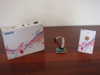
This user-programmable doorbell plays any melody you want when someone comes to your house and rings it.
I present this musical bell for the home, which allows the user to record the melody you want to ring when someone comes to your house and ring the bell, giving a twist with respect to common bell that only has one or more melodies established, without any option to change it to any place you want. Besides the driver standing at the door is wireless and touch sensor, facilitating installation to not need cable to connect the drive to bell.
Deputy photographs and schematics of the project (wired version), however, they can download more project data such as source code in the following link: https://www.facebook.com/hugotecnologia
Hope is to your liking and you can get free access to share with all amateur and professional world of electronic projects I'm designing now, besides my Facebook page can see other projects I've done. Thank you very much for your kind attention.
Discussion (4 comments)
Dieter Aschmann 6 years ago
Der Controller hat nur die Aufgabe auf einem Interrupt, ausgelöst durch den Optokoppler und Taster, zu warten. In der ISR werden im 22.05KHz Takt die 16 Adressbits hochgezählt und damit die Speicher adressiert. D0..7 Low und D0..7 High werden über ein R2R- Netzwerk in ein analog Signal nach Fiterung umgewandelt. Ein Verstärker IC sorgt für die nötige Lautstärke. Die Melodie wäre im Prinzip 12 Sec. lang um etwas Puffer zu haben habe ich mich auf 11,8 Sec beschränkt. Bei mir sind EPROMS 27C2001 im Einsatz. Da aber diese EPROMs abgekündigt sind gibt es diese nur noch bei Chinesischen Händlern. Empfehlung umsteigen auf kompatible EEPROM- Typen.
Kees Neele 7 years ago
The pushbutton is a metal rvs one with green led light ring , which flikkers during playback. No microprocessor needed.
The module needs ac coupling by the button , otherwise it plays continouesly.
ben16 6 years ago
Kees Neele 6 years ago
ben16 6 years ago
Thank you
Kees Neele 7 years ago
Kees Neele 7 years ago
image-20180309145511.jpeg (994kb)
image-20180309145512.jpeg (921kb)
Hugo.Tecnologia 10 years ago
Again share the schematic diagram of the actuator to the programmable musical bell, which will add the capacitor C2 at pin 7 of the microcontroller to give increased sensitivity to touch sensor, and the microcontroller enters the low power mode once culminates their work whenever operated, and prevent the rapid consumption of the battery.
Thank you all for following this project.
Niek.Laskarzewski 10 years ago
From Labs
I've been working on the programmable musical doorbel for a while now. The schematics, which i've included, were the schematics from the original material.
A few changes were made from the original material.
First of all, in the original material, there was a microcontroller wich drives the LED and HT12E. This was removed because it used a current of ~2.8mA continuously, this emptied the CR2032 battery within a week.
Further more, the DIP-switches, that were connected to the adress input of the HT12E and the HT12D, were replaced by two 2x8 pin headers so that the adress could easily be changed with jumpers, or the pads could be soldered together. Also we found out that the doorbel would automatically go off at random intervals. This is most likely because of other data around us, but this can be solved by not having the adress at bitwise 00000000.
Lastly a few minor changes were made, mostly component changes because of availability issues.
programmable-musical-doorbell-actuator-v11.png (17kb)
programmable-musical-doorbell-programmer-v11.png (11kb)
Niek.Laskarzewski 10 years ago
Hugo.Tecnologia 10 years ago