New Software for Network Connected Signal Analyzer (NCSA 2, 160362)

I recently bought the Network Connected Signal Analyzer from the Elektor shop.https://www.elektormagazine.com/labs/network-connected-signal-analyzer-150211
Software for this project can be found at GitHub. Also, make sure to read all the comments and project updates below, there is a lot of useful information.
Links & Resources
Version 1
- Network Connected Signal Analyzer, Part 1
- Network Connected Signal Analyzer, Part 2
- First Version at Elektor Labs
Version 2
Original text starts here
I recently bought the Network Connected Signal Analyzer from the Elektor shop.
https://www.elektormagazine.com/labs/network-connected-signal-analyzer-150211
https://www.elektor.com/network-connected-signal-analyser-150211-91
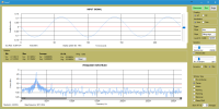
But I was not very happy with the supplied software. It is slow and there's a lot of functionality lacking. So I started changing the software and added the next features, all done in software:
- Triggering (Auto, Normal, Off)
- Trigger edge (rising, falling)
- Trigger level -250mv to 250mV
- Runing mode and Single shot mode
- AC/DC coupling
- Statistics of input signal
- Offloading calculations to other threads
- Changing UI
Here's a demo:
Because of the screencapturing the performance looks a bit slow. But is is much faster then the original because it now multithreaded. Measurements and calculations are not done on the UI thread but in separate threads.
I'd like to add more features very soon. Here's a list of what I like to add.
- Add the signal generator
- Add the Synthetic signal generator
- Add cursors to graphs
- Add min/max lines in graphs
- Calibration wizard for calibrating bias and gain.
- Logger functionality (slow sampling)
- Automatic selection of sample rate and amount of samples based on selected timebase.
- New graph with scope look and feel Intensity grading
- Use wpf instead of forms and change UI design.
- More triggering functions
- Fixed scales of graphs like a normal scope.
- Change dsPIC firmware so triggering can be done by hardware instead.
- Add external triggering
- Add bode plot with frequency sweep.
- Add possibility to change the input amplifier gain for weak signals to get maximum voltage resolution.
- Add hardware module to be placed in series with the input to be able to use a normal probe at 1MOhm, add selectable attenuators and AC/DC coupling. All selectable via software.
- Adding filter capability (IIR or FIR) to filter the input signal and make the signal available on the output. With a filter design tool
- Arbitrary waveform design tool and the possibility to upload the waveform to the generator.
I'll add the software to github soon. Its not ready yet.
If you have idea's please drop a note.
Project Elements
Discussion (6 comments)

Electroremy 7 years ago
In the French Elektor journal n°465, there is an article about a software and a firmware update of the NCSA.
They call it "ASPE II" - "NCSA II" in french
But I can't find it on Elektor Labs
So do you make a new update ?
Thanks

ClemensValens 7 years ago
The easiest way to just program the HEX file is by using Microchip's IPE Integrated Programming Environment, select the device (dsPIC33EP512MC502), your programming tool and the HEX file (dsPIC_Elektor.X.production.hex), then program the device.
Another way is to create a new project in MPLAB X: File -> New project, category Microchip Embedded, Prebuilt (Hex, Loadable Image) Project. Then choose HEX file, device (dsPIC33EP512MC502) and tool, click Next and then Finish. You can then program a device the same way as when you are developing code.

Electroremy 7 years ago
Indeed, I've already make the update.
But Elektor does not explain the firmware update procedure that I've done above un decembrer 13. Elektor suggests readers to send their NCSA for firmware update for some money. There is the firmware update procedure, just a little bit complex :
- download MPLABX-v3.45 from Microchip website (it's huge, 500Mo)
- install it
- then download and install the compilers xc8, xc16 and xc32 (about 60Mo each)
- I've also install the MCC plugin
- then connect PickIt3 USB port to your computer
- thus connect NCSA USB port to your computer (just for +5V supply)
- finally connect PickIt3 to the NCSA ISCP port ; be aware of the white arrow
- in MPLAB, open the "dsPIC_Elektor.X" project folder
- in MPLAB, clic on the icon "Make and program device" and choose menu "Programmer to go Pickit 3"
- wait for the end of programming
- then unplug NCSA ISCP port and Pickit3
- finally unplug NCSA USB and Pickit3 USB
And also MPLABX allows you to change some code, like default IP adress when DHCP is disable.
Best regards

breedj 7 years ago
I bought the NCSA after I read the first article in 2016. I then rewrote the software started this project on Elektor Labs. After that Neal Martini contacted me and we teamed up. You might have noticed that Neal and I are also the ones who wrote the NCSA II article of the May/June 2017 number you just read. So you can download the software from the github link in the project update above. But you probably have it already.

Electroremy 8 years ago
I've got the NCSA (original version bought at april 2016) and I'm just downloading new software files on github website
Also I've a Pick It 3
But I have never used the Pick It 3, and there are no manual in the gitub files
How to connect the Pick It 3 to the NCSA to update it ? Where is the upgraded firmware file ?
Can you make a tutorial for the firmware upgrade ?
Best regards

breedj 8 years ago
With this approach we cannot use the noise generator but have to sweep the frequency range. If we want to measure the duty cycle with a 1 degree accuracy we will need 360 samples for each period of the measured signal. The highest sample rate of the ADC is 1.1MS/s so the phase can only be measured up to 3055Hz. With an accuracy of 7 degrees we can have a range of 20kHz. So I do not know if it is really usable. It might just be.
A better idea would be using a timer of the microcontroller to do the duty cycle measurement. We might be able to use the debug header K6 for that purpose. The cpu runs at 8MHz. Then we might get a 22kHz range with one degree accuracy or 40kHz with 2 degree accuracy.
But maybe someone else has a better idea of doing phase measurements. I just made this one up in 10 minutes.
Unfortunatly I do not have the time to do extensive tests and write the software for this feature at this moment. I've got another project on LABS (10MHz reference) I am currently working on, which I started before rewriting the NSCA client software. I like to finish that project first and will take another month or so. Maybe you can have a go and do some tests. Be aware that I just grabbed some components from the eagle library. So I do not now if the LM393D is the correct comparator for this purpuse. It has to be able to work with a single supply rail of 5V and GND.
Joost

Electroremy 8 years ago
I have another idea : with a single input we cannot have at the same time amplitude and phase information, but I think amplitude OR phase with some extra hardware for the phase measurement ?
So to measure a device's response, we have just to proceed one time for the amplitude and a second time for the phase :-P
Thanks

breedj 8 years ago
In one of your previous posts you where asking about which windowing function to use. Here's some documentation with a handy table at the bottom.
http://www.ni.com/white-paper/4844/en/

Electroremy 8 years ago
I have the idea to have a tool for reparing devices like FM radios :-P ... indeed, a red pitaya is a good idea :-)
I've got another idea for the NCSA : now we just have the amplitude in dB of the signal ; it would be better if we can have both amplitude and phase
Also in audio applications phase matters
Thus the calibration should be done for both amplitude and phase
I have another question : the calibration is OK when I use both the noise gen and the input (typically to benchmark an amplifier) but what about a "standalone" signal measure ?
Indeed calibration consider the whole "loopback" measure chain ; but for a standalone signal measure, I need to calibrate the input separately :-P
PS : I've got two voltcraft MXG-9802A singal generators, and the sinus function of the NCSA is really better ! Also the NCSA cannot generate good square signals with hight frequencies.
Thanks

breedj 8 years ago
I could figure out what it would cost, roughly. It must be cheap. If it is too expensive you might be better of buying a red pitaya or such.
What frequencies do you have in mind for your application?

Electroremy 8 years ago
Now the NCSA (ASPE in french) is a easy to use good measuring tool for audio applications
Which are the better windowing function to use for audio quality tunning measurement ?
Do you think is it possible to have another elektor project with higher frequencies ? For radio or SMPS power supplies applications ? (I know it will be very more difficult and costs a lot !)
Bests regards

breedj 8 years ago
There are two new buttons and a set of radio buttons at the top of the screen.
Auto set: Will initialize and enable the white noise generator and sets the FFT averages to 25.
Calibrate: Stores the current FFT data in memory as calibration data and switches the FFT view to 'View calibrated spectrum'.
View uncalibrated spectrum: View the spectrum of the measured signal
View calibrated spectrum: View the spectrum corrected with the calibation data.
View saved spectrum: View the saved calibration data
It is advised to use at least 10 averages when using the calibration functionality to get a good measurement.
You can download the source code here as well as an already compiled application in the application binaries directory:
https://github.com/breedj/Elektor-Network-Connected-Signal-Analyser

nealmartini22@gmail.com 8 years ago
Additionally, the NCSA does allow you to "calibrate" the response to white noise. Looking at the lower right of the user interface there are two buttons that provide this capability. One (Save Spectrum) allows you to save the spectrum with white noise applied to the NCSA input. The other button (Saved-Current) allows you to take the difference between the saved spectrum and the spectrum you get once you insert the device your trying to measure (e.g. a HiFi amplifier). The difference represents the transfer function of the device.
I hope this helps.
Neal

Electroremy 8 years ago
The NCSA have a low-pass filter on it's input and output
The problem is that this low-pass filter makes a "false" measure when you want to use the NCSA to get the transfer function of a device (for eg. a HiFi amplifier)
It will be better if the software have a "calibrated" fonction that makes a falt frequency response with the white noise generator when the output is connected to the input.
Thanks.

breedj 8 years ago
Sorry about the lack of documentation. But as you described it is how it should be done.
The fixed ip addresses in the firmware only apply to the static addresses. The dhcp is enabled setting the jumpers to 0x3. You can do that by removing both IP jumpers (JP2) (they have pull-up resistors). In dhcp mode a mac address is assigned by the firmware. When using a second device on the same network you can add jumper 1 (the one with the arrow). That device will than also use DHCP but with another mac address. The other two jumper positions are the static addresses, but both with another subnet.
- Both jumpers removed: DHCP with MAC 00:08:dc:00:ab:cd
- Jumper at arrow installed, other jumber removed: DHCP with MAC 02:08:dc:00:ab:cd
- Jumber at arrow removed, other installed: IP: 192.168.0.123, MAC: 00:08:dc:00:ab:cd
- Both jumpers installed: IP: 192.168.1.123, MAC: 00:08:dc:00:ab:cd
Joost

Electroremy 8 years ago
And I can't connect to the NCSA trought my internet box or trought a router. When I plug the NCSA to my computer it's OK (the NCSA have 192.168.0.1 adress)
How to enable DHCP ?
My router have 192.128.123.X adress range

Electroremy 8 years ago
Finally I try to update firmware and it's OK :
- download MPLABX-v3.45 from Microchip website (it's huge, 500Mo)
- install it
- then download and install the compilers xc8, xc16 and xc32 (about 60Mo each)
- I've also install the MCC plugin
- then connect PickIt3 USB port to your computer
- thus connect NCSA USB port to your computer (just for +5V supply)
- finally connect PickIt3 to the NCSA ISCP port ; be aware of the white arrow
- in MPLAB, open the "dsPIC_Elektor.X" project folder
- in MPLAB, clic on the icon "Make and program device" and choose menu "Programmer to go Pickit 3"
- wait for the end of programming
- then unplug NCSA ISCP port and Pickit3
- finally unplug NCSA USB and Pickit3 USB
It works fine :-P

nealmartini22@gmail.com 8 years ago
If you have an unusual IP for your network router, the fixed IP in the original code version is easily modified to match your situation. However, the automatic DHCP IP assignment that is contained in the GitHub posted by BreedJ is a better solution. The code in the dsPIC33 and the C# project both need to be updated to have the DHCP function properly.
Also, for anyone interested in modifying the PCB for other applications, note that there is actually an unused Op Amp in the dsPIC33 that can be utilized with a few modifications, I have done this for another project. It is a bit messy, but doable. To do this you have to do three things:
1. reroute the ICSP programming pins from PGEC1/PGED1 to PGEC2/PGED2.
2. Move the W5500 chip select to some other I/O pin to free up PGEC2
3. Modify the FW so the currently used OP Amp in internally connected to the ADC to free up the OA1OUT for use as an OP Amp output instead of ADC AN3 input.
Have Fun!
Neal

Electroremy 8 years ago
Very great job !
Indeed, I’ve purchased a Network Connected Signal Analyzer (NCSA) from the Elektor shop but I was not very happy about the card and the software.
The NCSA is useful with its noise generator on the output and its input with spectrum analyzer software. You can use it to get the frequency and phase response of a HiFi device (amplifier, filters, …)
But the NCSA needs some extra features, both on the card and on the software.
On the card:
- Overvoltage protection on the input (we just need two 2N4148 and one resistor… it’s too bad that this feature is not included on the PCB)
- Gain attenuator on the input
- Peak level LED indicator (LED will light on when input signal is too strong, causing ADC saturation) ; this peak LED should be very useful to adjust gain
- AC/DC switch on input (like scope input panels)
- Amplifier for output, with adjustable level and adjustable offset
- Also, a low-noise power supply for the card and the new features below ; because USB +5V and other phone supply are very poor quality supplies…
On the software:
- Zoom on Y axis (that is to say, on the input voltage and the dB scales)
- More than 10 averages
- Function that can make a comparison between to spectrum, the first when input is backlooped on the output with noise generator, the second when the input and the output whit noise generator are connected to a device that we want to know frequency and phase response ; the result of the comparison will be the precise know frequency and phase response.
NB: the plastic with case sold with the NCSA was not appropriate at all: Reset button, loopback function, LEDs, connectors are not accessible when the card is in the case ! Thus, the card was not designed to fits in a case; indeed, all user-interface devices should be placed on the borders of the card and not on the middle!
NB: The 192.168.0.123, 192.168.1.123 and 192.168.2.123 IP make problems because I cannot plug the NCSA on my internet box (internet box have 192.168.123.XXX IP range). It will be very better if the NCSA have DHCP IP option!
To conclude: NCSA was a good idea but the product sold is not achieved. Also this is not a “ready-to-use” product.

breedj 8 years ago
This is the list of supported devices for pickit 3:
8-bit Devices – PIC10F/12F/16F
PIC10F/12F/16F5X
PIC16F6xx
PIC16F7XX
PIC16F8XX
PIC16F9XX
PIC16F1XXX
8-bit Devices – PIC18F
PIC18CXX/FXX
PIC18F1XXX
PIC18F2XXX/4XXX/6XXX/8XXX
PIC18FXXJ
PIC18FXXK
16-bit Devices
dsPIC30F/33F, PIC24F/H
32-bit Devices
PIC32MX

breedj 8 years ago
The last uP/uC projects I did before this one was with a motorola 68HC11 and Z80. So I also have to catch up.
For this project I changed the .NET code. The current firmware has been written by the original author Neal Martini. But if you have any questions you can ask me here or on the github page. The difference with the firmware which came with the board is only the DHCP. If you want to use that, just remove both jumpers.
If you have made any software or hardware upgrades can you let me know? I'm also plannning to make a new hardware version or add-on board. I like to have an attenuator, amplifier and a selectable 1MOhm input as well.

Electroremy 8 years ago
I don't have any dsPIC programmer... what product can you advice for me ?
In fact I started to program µC in year 2000 with AT89C2051... but I do not have enought time... now it's totally obsolete !!! Indeed computer and µC evolves too fast for me.
Also I have a lot of old PICs (like 16F84) that I never used... and all this components are now totally obsolete ! :-((((
My others hobbies : analog circuits, wood working, milling, backsmith, stay pretty the same that in the 1960's. For wood working, I'm still using my grand'father's tools, even if these tool are 70 years old !
For the NCSA, I want to make 3 things :
- use your firmware, thank you very much :-D
- trying your software, and make my own software, because I have digital signal processing and DOT.NET skills :-)
- make a extra-bord with output amplifier and all the needed features for input that I talk - but my extra bord will be a standard PCB and not a nice CMS double-sided bord... it's to bad because it will cause a loss of quality on hight frequencies !
Best regards <3

breedj 8 years ago
I like you're ideas and some of them are on my list as well. Most of them are easy and cheap to implement.
If you have a dsPIC programmer you can upgrade to the firmware from the github link I posted. It already includes DHCP support. I also was not able to connect before switching off some other device. That problem has been solved now.

nealmartini22@gmail.com 9 years ago
Since I wrote the original code, I would be interesting in collaborating and possibly including some changes I am working on to add software radio capability to the NCSA. I could also modify the PIC code as necessary to add the functionality for your filtering ideas.
Please let me know if you are interested in this type of collaboration.

ClemensValens 9 years ago
And part two hasn't even been published yet! Looking forward to see your finished program.
Regards,
Clemens

Updates from the author
breedj 9 years ago
https://github.com/breedj/Elektor-Network-Connected-Signal-Analyser/blob/master/Application%20Binaries/Elektor.SignalAnalyzer.zip
RICH OBERMEYER 8 years ago
most modern products with firmware have some form of boot loader built in to allow simple firmware upgrades in the field without buying a pickit3 or opening the product and plugging in a cable.
breedj 8 years ago
RICH OBERMEYER 8 years ago
https://zavax.wordpress.com/2013/02/19/designing-bootloader-for-microchip-dspic33epic24e-micro-controller-1/
breedj 8 years ago
frp 8 years ago
Thanks
breedj 8 years ago
I'm currently busy with other things but will resume this project at the end of this year. The bootloader has not been implemented yet. So unfortunatly the only way to use the latest firmware of this labs project is to use a pickit3 programmer. The bootloader is the first thing on the list though.
RICH OBERMEYER 8 years ago
In March it was exciting. Here in almost October it looks like it died out and lost interest which also kill elektor readers interest. Breed suggested he might get back from something else more exciting by end of year.
The boot loader is critical and that needs to come from the factory or each user has to buy a pickit, install all the software, and figure out how to make it work. A built in UI boot loader makes it trivial for newbies to get excited. They really can make their own features.
A roadmap and wiki might get some interest going.
It needs a champion and right now I don't see one.
I held off buying mine until I see it moving. Right now it's not looking like a HOLD, not a BUY status.
breedj 8 years ago
One problem is that if we manage to get the bootloader working, all who already bought a signal analyser still need to use a programmer to load the bootloader for the first time. Also the boards which are in the elektor shop will have to be sold with that firmware. Otherwise there's no point in making it because only who have a programmer are able to use the bootloader. That doesn't make sence. I do not know if elektor is planning to use the new firmware when its ready.
RICH OBERMEYER 8 years ago
Well its not your project so I understand your contributions have already been huge helping out. I would guess that Neal has dropped the ball which is of course his option as well. I am not suggesting either of you "has" to do anything. But if this is the end it would be nice for everyone reading about this that this is it.
I liked this project. I also had other projects I have been consumed with when this project came out. I am currently finishing my custom 500mm 3D printer. 400mm/sec print speed. Hope I don't get consumed printing 3D crap for the next 6 months. The nights are never long enough :-}
I was looking at this project as a potential next project. However disappointed with the progress on this project in the last 8 months. I have done the bootloader before and have a pickit3. But I hate the MicroCrap development tools and hardware. They hang and crash continually on me. Maybe its all me, who knows but when I use an ST or NXP ARM processor on the same machine I am debugging my code, not the tools. Never had a crash with Keil that I didn't expect.
If you guys aren't going to move forward then I might do my own thing starting with an ARM based board with a few of the features you suggested included. Probably start next month. The C++ will be my biggest challenge but I am not afreaid of that.
breedj 8 years ago
I do not think this is the end of the project. I just didn't want to spend months on this project. And I was hoping that more people might be wanting to help coding. That's why I've put the code on github.
I think your ARM based project will be an interesting project. I hope you will post it on this web site. If there is one one thing I would change it would be swapping the network connection with a high speed usb connection. We were actually making a high speed continuous mode and implementing SDR. But Neal had a lot of trouble getting the data from the analyser to his pc because of his network at home. That's when this project stalled.
By the way. I'm also busy with my 3D printers, both delta and carthesian types. That hobby consumes a lot of time as well. I guess that the 400mm/s you mentioned is travel speed, not actual printing speed? I think building 500mm printer is quite challenging if you want 0.1mm accuracy on all axes. Also very interesting stuff...., but another topic.
RICH OBERMEYER 8 years ago
I was thinking of increasing the network speed to increase throughput. I would never go to USB. To slow and forces you to be attached to a noisy PC. I would go wireless before USB. I wanted to support POE so it is completely remote but powerful. I would like to understand the reason behind the problem with the network. Did you hear back from Neal yet?
What do you think about QT instead of C++? Universal platform will get more attention.
3D printer: Delta. Getting Carthesian to move that fast would be a serious unsuccessful project I suspect. I am targetiing 400mm/s print speed! 200 is common. Travel speed is up about 500-600mm/sec. DC Servos not steppers. Lot of new motor controllers coming out now. Use BLDC motors, they rock and are quiet.
Changing the filament injection obviously has been a big design challenge. Increased the area where the filament gets melted and increased heat (40Watt heater). Changed the extruder to be able to push that much filament. Have not tried Nylon yet at speed which may be impossible to run that fast. The retract still needs tuning. When you have that much melted filament sitting there it tends to come out the tip no matter what the retract is set to.
breedj 8 years ago
POE would is something most people do not have at home. Most routers/switches do not have POE capability. Only the more expensive ones have it. But I guess you will make it in such a way that it will be possible to power it with a dc adapter as well.
The problem Neal encountered has not been solved as far as I know. I think he got stumped and gave up. I cannot blame him, I would be very frustrated as well. He spend a lot of time on it. He encountered too many tcp resends. We were sampling at 504201 Hz and sending blocks of 1024 samples. Unfortunatly the dspic could barely keep up the data rate. We reached about the maximum SPI rate of 15MHz (tcp has a lot of overhead). When one DMA block was filled with samples the other was send to the PC. But sending through the w5500 is a blocking operation. And if there are one or more resends the sending takes longer. Too long actually. Sending could not keep up the the sampling and glitches occured. Sometimes the dsPic or w5500 stalled completely. Neal got tcp resends very often even with only his pc, analyser and a switch as a separate network. He also tried other pc's and network equipment, with the same result. I was not able to reproduce that problem though. It all worked fine here. But if one of us has trouble then chances are that someone else can will have the same problems. The solution should work for everyone. We also tried UDP, but that did not work out as well. We also cannot affort to loose any data or receive it in the wrong order. So we had to stick with tcp. I think using USB will not have this problem because there is less change of congestion. Its just the analyser and the pc.
The current application is written in C# (.NET framework) because that's wat I use as a professional software developer every day. I never used QT, but it looks great. It would be great if the client application would be able to run on other devices like tablets as well. I think QT is free to use when used with a certain open source license model.
I like the idea of the brushless motors. I use them with my drones (8 motors, 1m diameter) and model helicopters (1.2m rotor diameter). There is an article about using dc motors with a closed loop pid controller for use in a 3D printer in the last two issues of Circuit cellar.
I also have retraction problems like you have. I do not think you can solve that easily. The problem is that retracting the fillament does not create a vaccuum inside the nozzle. Air can get inside easily. So it does not suck the filament back into the nozzle as you would expect. Retracting only reduces the oozing because there is less pressure of the fillament. Therefore there is no use in having more than 2 - 4mm retraction.
Don't you have problem with printing layers too fast on top of each other? I never print faster than 60mm/s because if a layer is printed on top of one which has not been able to cool down yet it will become a mess. Even with a fan.
I like to see your printer in action. Do you maybe have a movie you can show?
RICH OBERMEYER 8 years ago
If I put 2 USB cameras on the same USB root hub on my 3D printer for pick and place it crashes the computer. Most laptops only have one root hub for users. Not even close to 480Mbits and the PC can't handle it.
More important it picks up noise and ground loops from the computer which is huge. Makes analyzing low level signals impossible. Continuous traffic trashes USB in my experience. Not going there again. However I have TCP connections doing plenty of traffic with no problems.
For POE I use a POE adapter which is a wall wart so the high end router is not needed. The adapters are cheap now.
The problem with high speed printing is generating enough hot plastic so it can move quickly and then a low speed mode for slowing it down. No mechanism to handle the difference. I am trying a 3 headed design (diamond) http://reprap.org/wiki/Diamond_Hotend now. The top of the printer is off now while I add 2 more extruders. That has potential to solve the problem. Smaller heat chambers but 3 of them for speed when needed. I would post a video of the 3D printer but here it is out of context. This thread is for Neal.
Nice Drone! Mine has only been 10 inches or so. No manly ones like yours and your copter.
breedj 8 years ago
I contacted Neal. Neal was enyoing the summer. That's why nothing happened. We will slowly startup the project again when the days are getting colder and shorter. But the bootloader will not be a high priority functionality. That functionality will only be interesting if Elektor is willing to incorporate it in products they sell in the future. Otherwise it has no point because you will need a programming tool to upload the bootloader.
I find the diamond hotend quite interesting. Its huge. I've always liked the E3Dv6 series it uses. Its one of the best. I hope it works out for you.
I've got two drones now. The largest is more than 1m in diameter and has 8 577W 400kV motors with 300mm propellers. It runs on 22.2V with a 16Ah LiPo battery (for 15 minute flights). A total of 4.6kW maximum power. It ways about 6kg total and can carry 4kg extra payload. But I think I will sell it. I like building them. But flying is a bit boring. Here in the Nehterlands there are new regulations coming up. It will not be allowed to fly more than 100 meters away and not higher than 50m. Also flying FPV is not allowed. So its no fun unless you are a photographer. But then you will need certificates and always fly with two persons. One pilot and one photographer. I'll stick to my helicopters (TREX 600) instead. Those are the same size but more suitable because you usually do not fly more than 100m away.
breedj 9 years ago
https://github.com/breedj/Elektor-Network-Connected-Signal-Analyser
ClemensValens 9 years ago
breedj 9 years ago
Here's a list of the new features:
More to come!
ClemensValens 9 years ago
breedj 9 years ago