An old man stands up and is a veteran with a long tradition, especially here at Elektor. With MCS-BASIC-52 I have dared to make a fresh restart.
O-M-S-U is not concerned with developing something groundbreakingly new, but rather with bringing "old" and proven things up to date. The aim of this project is to show that technology from "yesterday" can still be used profitably for real projects and for training while still being fun. With a high-level language that is easy, understandable and quick to learn and that paved the way for a whole generation to use computers. If you also enjoy "retro" then you've come to the right place. There are countless descriptions of MCS-BASIC-52 on the Internet. The Elektor website is a good place to start. On this topic I can highly recommend the book "Mikrocontroller-Praxis ISBN 3-928051-58-X" by Andreas Roßrucker, published in 1994 by Elektor-Verlag. Unfortunately, this book is very difficult or even no longer available. Perhaps the Elektor publishing house can bring itself to offer such old but very well-made books as PDFs for sale. It has an excellent didactic structure and can be used as a guide for training or as a reference work.
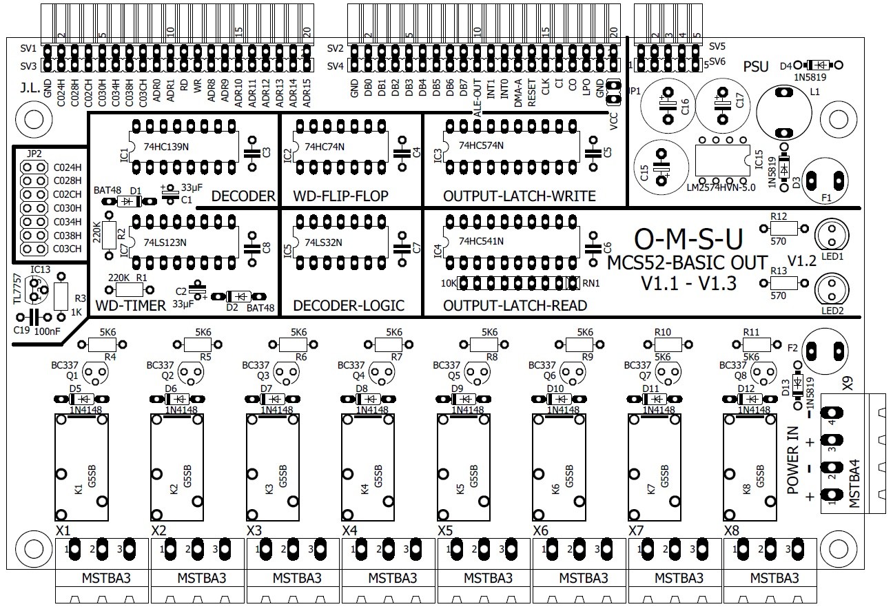
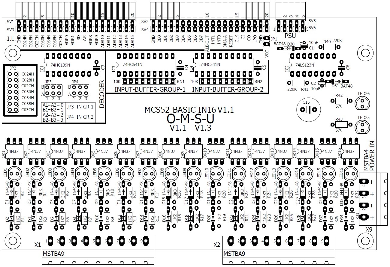
For the O-M-S-U CPU published here, I will also publish the expansion cards that I have already finished. The first expansion card is an output card with 8 relays on board. However, these are not the usual standard circuits. The 8-way relay circuit board includes a way to read back the output states and a Watchdog that switches off all outputs if BASIC is stopped or a software error occurs (who would like it if motors could simply run uncontrollably). The second expansion card is a 16-way input card that can handle an input voltage of 24VDC and is galvanically isolated from the control voltage via optocouplers. This input card has a classic design, as you would expect.
With just these two expansion cards, you can build nice little control units (PLCs) and MCS BASIC-52 can do what it was originally intended for.
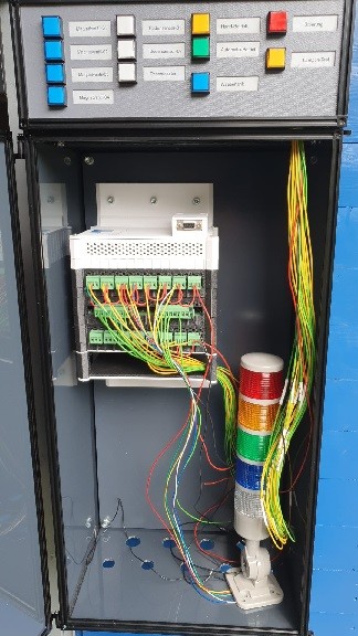
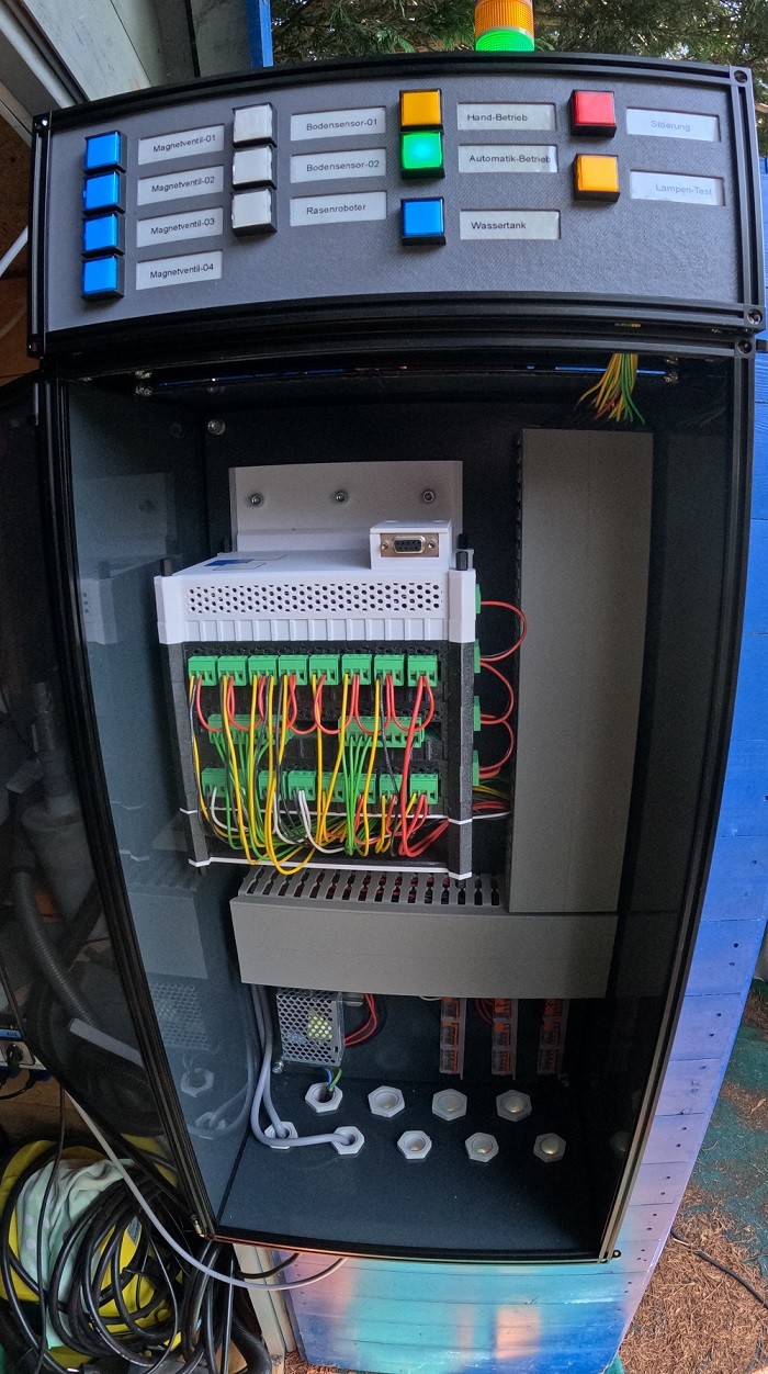
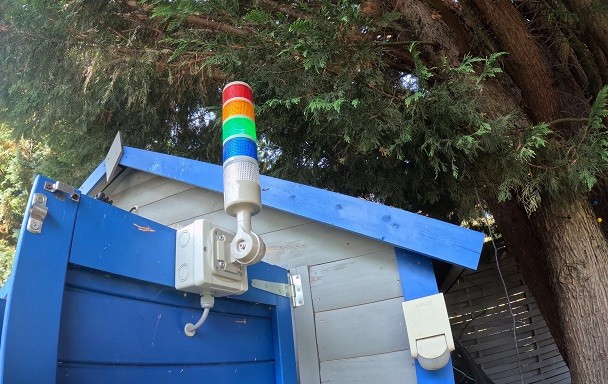
I admit that this garden irrigation control could have been made even smaller with the O-M-S-U control, but that wasn't important to me, as this control works safely and reliably. It will probably still work when I'm retired. But building the housing with MakerBeem was also great fun, and that's what it's all about in the end? Learning and having fun.
O-M-S-U garden irrigation as an example
I am very sure that more expansions will follow! I'm having a lot of fun with this project and I hope many other electronics enthusiasts feel the same way.
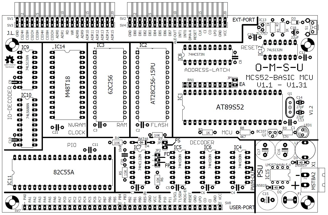
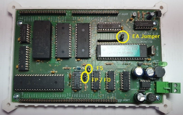
JUMPER There are three jumpers on this board, that's all. Jumper EA = Used to switch between internal or external program memory. If EA-Jumper not plugged = internal program memory (MCS-BASIC-52) Else EA=plugged = external program memory This jumper does not need to be plugged in to use MCS-BASIC-52 . FS-Jumper = FLASH-SAVE is used to protect the FLASH memory from accidental deletion or overwriting. If you want to save new programs on the FLASH, this jumper must be plugged in.
Jumper-FP/FD = Flash Prog or Flash Direct. This jumper must be set to FD when using MCS-BASIC-52 version 1.3. When using version 1.1, this jumper must be set to FP. If you want to delete the flash memory in the system with version 1.1, you have to load a small BASIC program and set this jumper to FD. In version 1.3, the jumper can always remain set to the FD position. The goals at a glance
Reliability and clarity.
Good availability of components.
Easy access to all important signals.
Easy to assemble even for beginners.
Easy to maintain and repair.
Compatible with MCS-BASIC-52 V1.1 to V1.3.
Easy expandability and wide range of functions.
Reliability and clarity
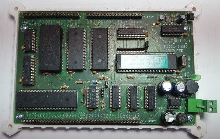
The circuit is housed on a circuit board in EURO format. The individual function groups are clearly divided and labeled using the assembly print, so that even a novice can find his way around the circuit board very quickly. The circuit itself is based on the Compuboard (Elektor issue April 1991) by Hubert Reelsen, which was also used in the Elektor book (Microcontroller Practice) from 1994 by Andreas Roßrucker. The circuit from back then was well thought out and has been tried and tested. The circuit design was only expanded with the necessary adjustments and additions. The circuit board has its own DC/DC converter, which was designed in such a way that it is more than adequately dimensioned for the circuit. With an input voltage range of 9V to 35V and an output voltage of 5V at max. 500mA, there is enough reserve for your own extensions. The OMSU board requires a maximum of 80mA when fully assembled. The expansion ports are based on the principle of today's Arduino boards.
Good availability of components
The components are available from the usual dealers. You can't get everything from one dealer, but you can easily put together the components you need from various sources. The 82C55 is available in the PDIP version on eBay and the author has already purchased it from various suppliers there without being disappointed.
Easy access to all important signals.
All signal lines are easily accessible via the socket strips or the components themselves, so that it is not a challenge to carry out measurements. This is particularly advantageous for training purposes but also for developing your own circuits.
Easy to assemble even for beginners
The consistent use of wired components is particularly beneficial for soldering beginners. In addition, all ICs used are designed with precision sockets, which prevents the components from overheating due to soldering for too long.
Compatible with MCS-BASIC-52 V1.1 to V1.3
The circuit design was changed so that the circuit is fully compatible with the MCS-BASIC-52 V1.1, V1.2 as well as with version 1.3 published in Elektor by Detlef Wulf and Hans-Jürgen Böhling. To ensure compatibility between the versions, only one jumper needs to be moved. All versions of the MCS-BASIC-52 should be located in the internal 8K flash memory of the AT89S52 for the full range of functions. However, since the AT89S52 has an ISP interface and the versions are available in Intel HEX or binary format, this hurdle is now very easy to overcome. There are some good descriptions on the Internet. I am also working on a simple how-to so that this process will be even easier for beginners.
Easy expandability and wide range of functions
All necessary and important signals are routed to socket strips on the long sides of the circuit board (similar to Arduino boards). The expansion is therefore very easy to solve thanks to the sandwich design and functionally reliable devices can also be designed for your own projects. When fully equipped, the circuit offers a number of additional expansion options. This includes the real-time clock with NV-RAM, an 82C55, for example for an LCD text display with buttons, as well as the fully routed address and data bus with additional address decoder, which greatly reduces the effort required for your own I/O expansions. The board can also offer an I2C interface implemented in software if the expansion written by Detlef Wulf and Hans-Jürgen Böhling is stored in the external flash. The original expansion was only slightly adapted to the OMSU hardware by the author and is available with source code and as a HEX file. This software expansion then gives you the option of accessing the popular i2C interface directly from BASIC.
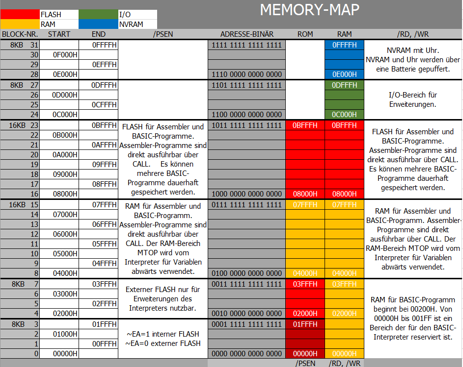
Memory allocation
The internal code memory consists of the 8052-BASIC's internal FLASH, which uses addresses 0 to 1FFFh. In addition, an external data memory (RAM) starting at 0 hex is required. BASIC-52 reserves the first 512 bytes (0-1FFh) of RAM for its own use and stores the current BASIC-52 user program immediately above it, starting at address 200h . The memory map shows a 32K RAM that uses the entire range from 0 to 7FFFh. (The 8052 also has 256 bytes of internal data memory, not shown in the memory map.) A 16K block combines code/data memory and is reserved from 8000h - BFFFh. Above this block of code/data memory is the I/O area, which runs from C000h to FFFFh. The actual area intended for I/O interfaces is in the range from C000h to DFFFh . This area is already partially decoded (more below) and is connected to the expansion port with its own connections. From address 0E000h to FFFFh in the I/O area, the NVRAM is provided, which also contains a real-time clock (depending on the component). If this NVRAM is omitted, this I/O area is also completely available to the user.
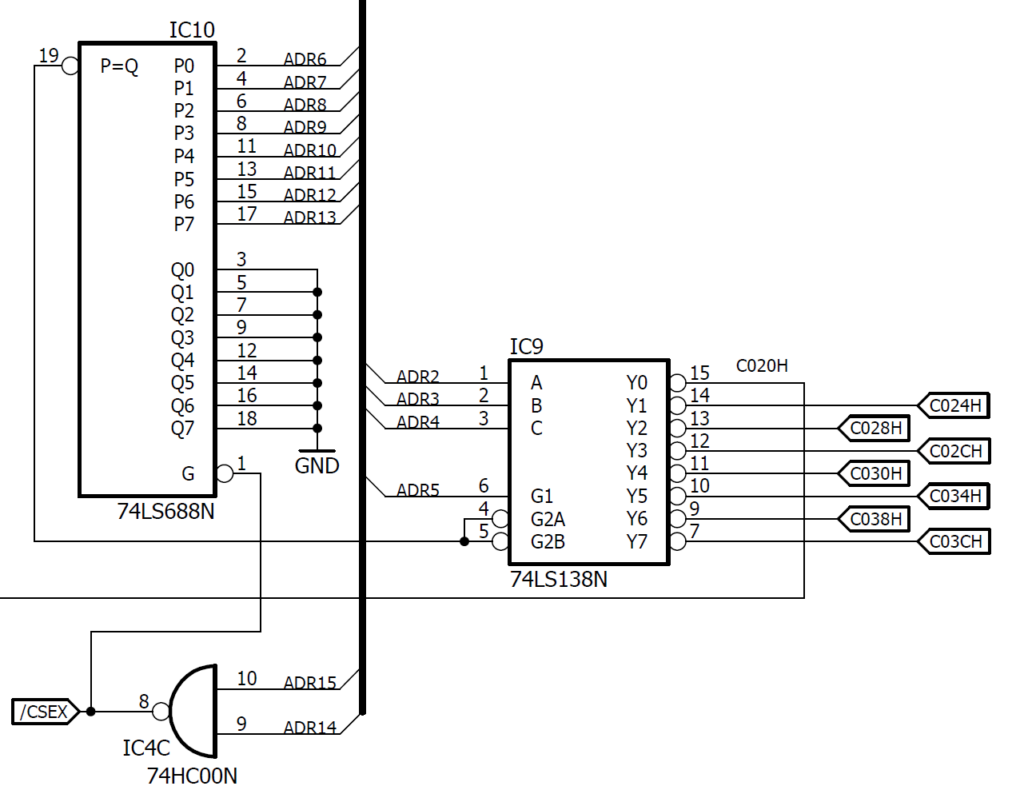
I/O address assignment in detail
Free I/O address range (not decoded on OMSU) Free for own I/O 0C000Hex Bin 1100000000000000 Free for own I/O 0C001 Hex Bin 1100000000000001 Free for own I/O 0C002 Hex Bin 1100000000000010 Free for own I/O 0C003 Hex Bin 1100000000000011 Free for own I/O 0C004 Hex Bin 1100000000000100 Free for own I/O 0C005 Hex Bin 1100000000000101 Free for own I/O 0C006 Hex Bin 1100000000000110 Free for own I/O 0C007 Hex Bin 1100000000000111
Compactflash interface address ( not decoded on OMSU Elektor 5/2003) P8255A Address Port A 0C008Hex Bin 1100000000001000 P8255A Address Port B 0C009 Hex Bin 1100000000001001 P8255A Address Port C 0C00A Hex Bin 1100000000001010 P8255A Address Control 0C00B Hex Bin 1100000000001011
Free I/O address range ( not decoded on OMSU ) Free for own I/O 0C00CHex Bin 1100000000000100………………………………………………………………………………….. ………………………………………………………………………………….. ………………………………………………………………………………….. Free for own I/O 0C01FHex Bin 1100000000011111
Free I/O address range ( not decoded on OMSU ) Continuation Free for own I/O 0C040Hex Bin 1100000001 000000 ………………………………………………………………………………… .. ………………………………………………………………………………….. ……………………………………………………………………………………………… .. Free for own I/O 0DFFFHex Bin 11011111111111111
LCD and button interface address (decoded on OMSU) P8255A on OMSU CPU-BOARD P8255A address port A 0C020Hex Bin 1100000000100000 P8255A address port B 0C021Hex Bin 1100000000100001 P8255A address port C 0C022Hex Bin 1100000000100010 P8255A address control 0C023Hex Bin 1100000000100011
Free I/O address range ( decoded on OMSU ) Free for own I/O 0C024Hex Bin 1100000000100100 Free for own I/O 0C025Hex Bin 1100000000100101 Free for own I/O 0C026Hex Bin 1100000000100110 Free for own I/O 0C027Hex Bin 1100000000100111 Free for own I/O 0C028Hex Bin 1100000000101000 Free for own I/O 0C029Hex Bin 1100000000101001 Free for own I/O 0C02AHex Bin 1100000000101010 Free for own I/O 0C02BHex Bin 1100000000101011 Free for own I/O 0C02CHex Bin 1100000000101100 Free for own I/O 0C02DHex Bin 1100000000101101 Free for own I/O 0C02EHex Bin 1100000000101110 Free for own I/O 0C02FHex Bin 1100000000101111 Free for own I/O 0C030Hex Bin 110000000011 00 00 Free for own I/O 0C031Hex Bin 1100000000110001 Free for own I/O 0C032Hex Bin 1100000000110010 Free for own I/O 0C033Hex Bin 1100000000110011 Free for own I/O 0C034Hex Bin 110000000011 01 00 Free for own I/O 0C035Hex Bin 1100000000110101 Free for own I/O 0C036Hex Bin 1100000000110110 Free for own I/O 0C037Hex Bin 1100000000110111 Free for own I/O 0C038Hex Bin 110000000011 10 00 Free for own I/O 0C039Hex Bin 1100000000111001 Free for own I/O 0C03AHex Bin 1100000000111010 Free for own I/O 0C03BHex Bin 1100000000111011 Free for own I/O 0C03CHex Bin 110000000011 11 00 Free for own I/O 0C03DHex Bin 1100000000111101 Free for own I/O 0C03EHex Bin 1100000000111120 Free for own I/O 0C03FHex Bin 1100000000111111
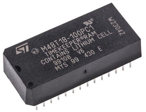
NVRAM and TIMEKEEPER address range (decoded on OMSU) NVRAM 0E000Hex Bin 1110000000000000 ………………………………………………………………………………….. ………………………………………………………………………………….. NVRAM 0FFFFHex Bin 11111111111111111BASIC example real-time clock
REM ****************************************************************************************** REM * TEST PROGRAM INTERNAL CLOCK TIMER 0 REM * WITH REAL TIME CLOCK M48T18 TIME REM * QUARTZ XTAL=11059200 REM * The time and date are entered manually and saved in the real time clock. In the event REM * of a power failure, the real time clock continues to run (power reserve). REM * When the system is switched on again, the internal clock TIMER 0 REM * is reset via the real time clock (M48T18) and continues to run without any loss of time. REM * The real time clock must have been set at least beforehand so that the function can REM * be established. The leap year is taken into account by the software . REM ******************************************************************************************
REM ——— BACKGROUND CLOCK SETUP ————
5 BLED=PORT1 10 INPUT "SET TIME? (YES=7)" X 20 IF X<>7 THEN GOTO 90 30 INPUT "ENTER TIME IN H,M,S > " HR,MIN,S 40 INPUT "ENTER DATE IN D,M,Y > " DAY,M,YEAR 50 INPUT "DAY OF THE WEEK (1=MONDAY) > " WDAY 60 PRINT:PRINT:PRINT:PRINT 80 GOSUB 61400 90 CLOCK0:TIME = 0:ONTIME 1,60000 95 GOSUB 61200: CLOCK1
REM ********************************************* REM ———————————————————————— REM MAIN PROGRAM REM ———————————————————————— REM *********************************************
100 PRINT CHR(27),: PRINT „[1J“ 120 PRINT:PRINT:PRINT:PRINT 130 PRINT “ DATUM“,DAY,“.“,M,“.“,YEAR, 140 PRINT “ ZEIT“,HR,“:“,MIN,“:“,S, CR, 160 FOR I = 1 TO 200: NEXT I 170 GOTO 130
REM ———– MAIN PROGRAM END ————– REM ————————————————————————
REM ********************************************* REM * ONTIME INTERRUPT HANDLER REM *********************************************
60000 TIME=0 60010 ONTIME 1,60000 60020 GOSUB 61000 60030 RETI
REM ********************************************* REM * CALCULATE TIME AND DATE REM *********************************************
61000 BLED=BLED.XOR.32:PORT1=BLED 61010 S=S+1 61020 IF S>59 THEN S=0:MIN=MIN+1 61030 IF MIN>59 THEN MIN=0:HR=HR+1:GOSUB 61200 61040 IF HR<24 THEN RETURN 61050 HR=0:WDAY=WDAY+1 61060 IF WDAY>7 THEN WDAY=1 61070 DAY=DAY+1 61080 IF DAY>29.AND.M=2 THEN DAY=1:M=M+1 61090 IF DAY>28.AND.M=2.AND.(4*INT(YEAR/4)<>YEAR)THEN DAY=1:M=M+1 61100 IF DAY=31.AND.(M=4.OR.M=6.OR.M=9.OR.M=11)THEN DAY=1:M=M+1 61110 IF DAY>31 THEN DAY=1:M=M+1 61120 IF M>12 THEN M=1:YEAR=YEAR+1 61130 IF YEAR>99 THEN YEAR=0 61140 RETURN
REM ********************************************* REM * READ CLOCK FROM M48T18 REM * AND SET INTERNAL CLOCK REM *********************************************
REM ——– SET STATUS TO READ ————- 61200 STAT_C=XBY(0FFF8H):STAT_C=STAT_C.OR.64:XBY(0FFF8H)=STAT_C REM ——— READ BCD SECONDS ————- 61210 BCD=XBY((0FFF8H+1H)) REM – BCD >=128 STOP BIT SET CLEAR ST-BIT – 61220 IF BCD >=128 THEN XBY((0FFF8H+1H))=0 61230 GOSUB 61350:S=DEC REM ——— READ BCD MINUTES ————– 61240 BCD=XBY((0FFF8H+2H)):GOSUB 61350:MIN=DEC REM ——— BCD READING HOURS ————– 61250 BCD=XBY((0FFF8H+3H)):GOSUB 61350:HR=DEC REM ——– READING BCD DAY OF THE WEEK ————- 61260 BCD=XBY((0FFF8H+4H)):BCD=BCD.AND.7:GOSUB 61350:WDAY=DEC REM ———— READING BCD DAY ————— 61270 BCD=XBY((0FFF8H+5H)):GOSUB 61350:DAY=DEC REM ———– READING BCD MONTH ————– 61280 BCD=XBY((0FFF8H+6H)):GOSUB 61350:M=DEC REM ———— READING BCD YEAR ————– 61290 BCD=XBY((0FFF8H+7H)):GOSUB 61350:YEAR=DEC REM ——– CLEAR STATUS ON READ ———– 61300 STAT_C=XBY(0FFF8H):STAT_C=STAT_C.AND.63:XBY(0FFF8H)=STAT_C 61310 RETURN
REM ********************************************* REM * CONVERT BCD TO DECIMAL REM *********************************************
61350 DEZ=0:IF 128=(BCD.AND.128) THEN DEZ=DEZ+8 61355 IF 64=(BCD.AND.64) THEN DEZ=DEZ+4 61360 IF 32=(BCD.AND.32) THEN DEZ=DEZ+2 61365 IF 16=(BCD.AND.16) THEN DEZ=DEZ+1 61370 DEZ=DEZ*10:DEZ=DEZ+(BCD.AND.15) 61390 RETURN
REM ********************************************* REM * SET CLOCK OF M48T18 REM * AND SET INTERNAL CLOCK REM *********************************************
REM ——– SET STATUS TO WRITE ———— 61400 STAT_C=XBY(0FFF8H):STAT_C=STAT_C.OR.128:XBY(0FFF8H)=STAT_C REM ——— BCD SET SECONDS ————– 61410 DEC=S:GOSUB 61500:XBY((0FFF8H+1H))=BCD REM ———- BCD SET MINUTES ————– 61440 DEC=MIN:GOSUB 61500:XBY((0FFF8H+2H))=BCD REM ———- BCD SET HOURS ————– 61450 DEC=HR:GOSUB 61500:XBY((0FFF8H+3H))=BCD REM ——— BCD DAY OF THE WEEK SET ————- 61460 DEC=WDAY:GOSUB 61500:XBY((0FFF8H+4H))=BCD REM ———— SET BCD DAY —————- 61470 DEC=DAY:GOSUB 61500:XBY((0FFF8H+5H))=BCD REM ———– SET BCD MONTH ————— 61480 DEC=M:GOSUB 61500:XBY((0FFF8H+6H))=BCD REM ———— SET BCD YEAR ————— 61490 DEC=YEAR:GOSUB 61500:XBY((0FFF8H+7H))=BCD REM ——– CLEAR STATUS ON WRITE ———- 61495 STAT_C=XBY(0FFF8H):STAT_C=STAT_C.AND.63:XBY(0FFF8H)=STAT_C 61496 RETURN
REM ************************************* REM * CONVERT DECIMAL TO BCD REM *************************************


Discussion (3 comments)