

OBD2 for Arduino
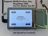
Arduino OBD2 diagnostic tester supporting Diamex DXM and Pi-OBD (AGV) modules
This project turns the Arduino into an OBD2 on-board diagnostic tester. So, the Arduino can read OBD2 vehicle data and it can read and clear emissions-related diagnostic trouble codes and inspection/maintenance readiness monitor data.
1. Supported OBD2 Features
Further features and more details can be found in my other OBD2 projects for the Elektor OBD2-Analyser NG and the OBD2 for Raspberry Pi project (chapter 4.4 OBD2 Diagnostic Services supported by HHGui/HHEmu).
2. Hardware Requirements
Parts used for the prototype:
(1) Arduino M0 and Arduino Zero should work as well, even if the Zero has 2 pins (Arduino pin 2 and 4) swapped compared to the M0/M0 Pro.
(2) Any other TFT touch shield working with 3.3V logic levels can be used if you are able to adapt the drivers coming with the shield to my software.
(3) Any other prototype board or no prototype board at all. That depends on the actual installation, see chapter 3.
(4) The old Diamex DXM OBD2 module is supported, too if you find a shop that still has it.
(5) The Pi-OBD module features two pins (5V, GND) to power the TFT display on the Pi. A selfmade Pi-OBD module 5V, GND pins to Arduino micro USB adapter could be used to power the Arduino. Do not try to power the Arduino at its 5V output pin! Without further protective diodes soldered in, this might destroy the regulator on the Arduino.
3. Hardware Preparation
The setup of the prototype is described here. Dependend on the actual installation you use for your handheld diagnostic tester (see chapter 3.4.2), your setup might differ.
3.1 Waveshare TFT Touch Shield
Solder 3 null Ohm resistors/jumpers on the backside of the TFT touch shield to route the SPI signals to Arduino digital pins 11, 12 and 13. I used short pieces of wire and soldered them on the jumper pads.
3.2 Microbot PCB Proto Shield UNO for Arduino
Solder the 4 pass-through connectors in that come with the shield.
Do not solder the ICSP header in!
The Microbot Proto shield is made for the UNO. On the UNO the ICSP header is connected to pins 11 MOSI, 12 MISO and 13 SCK.
The same wiring is found on the Proto shield. However, on the M0 Pro the ICSP header is connected to other pins 18, 21, 20 (SAMD21 PA12 MISO input, PB10 MOSI output, PB11 SCK output) and pins 11 PA16, 12 PA19, 13 PA17 (LED output) are used or free for other purposes. So, with the ICSP header soldered in, the Proto shield would at least shorten the PB11 and PA13 output port pins on the M0 Pro.
3.3 Wiring
Connect OBD2 module Tx to digital pin 0 that is used as Arduino Rx.
Connect OBD2 module Rx to digital pin 1 that is used as Arduino Tx.
For the first setup use 2.2 kOhm resistors in the Tx and Rx lines, so that no ports are destroyed, if you make a wiring error. In the error case a current of
I = U/R = 3.3V/2200Ohm = 1.5mA flows, that is below the SAMD21's limits.
Connect OBD2 module Ground to any GND pin, e.g. Arduino pin 14.
If the Pi-OBD Module is used, connect Pi-OBD Module Reset to Arduino pin 8.
If the Pi-OBD Module is used, connect Pi-OBD Module BIOS/Bootloader to GND (BIOS).
3.4 Installation of the OBD2 Module
3.4.1 Installation of the DXM OBD Module
For the DXM module that is easy. Due to its small size, it can be soldered/fixed on top of the prototype shield. The wiring can be found in chapter 2.1 of my other project here.
3.4.2 Installation of the Pi-OBD Module
As you can see in the images, I have just built a prototype using a breadboard. My Pi-OBD module was modified with a 2x13 pin stacking header for an update of the OBD2 for Raspberry Pi project. That header prevents an easy installation now.
If you want to build a real handheld diagnostic tester, there are at least three solutions.
Solution 1 (for experts only, yields the least stacking size)
You carefully have to make two changes to the Pi-OBD module.
First, desolder the pin header on the module or try to get one from Diamex without it.
Second, cut the PCB next to the two mounting holes on the right side of the PCB (orientation see ASCII art below).
Now, the Pi-OBD module can be moved in from the left until its left PCB side (that one with the two remaining mounting holes) hits the Arduino headers. With that changes, the Pi-OBD module exactly fits under the TFT touch shield and above the prototype shield.
After soldering the wiring, attach a layer of thin isolation between prototype shield and Pi-OBD module, e.g. use hot glue.
Also take care that the condensers on the Pi-OBD module do not touch the TFT touch shield, e.g. attach isolating tape on the condensers.
For additional space, the unused ICSP header on the TFT touch shield could be desoldered.
If you do not want to make that irreversible change to your new Pi-OBD module, there are two other solutions.
Solution 2 (simplest)
Simply mount the Pi-OBD module under the Arduino. My Arduino is mounted in a case. The Pi-OBD module's mounting holes placements differ from the Arduino's mounting holes placements. If 4 additional holes are drilled into the case, the Pi-OBD mounting holes can be used to screw the Pi-OBD module to the Arduino's case. If there is not enough space between Arduino and case, use plastic screws or use hot glue to fix the Pi-OBD module to the case. Then, the Pi-OBD module's mounting holes could be used to mount the whole construction in a case.
note:
If you choose this solution and come to the idea to remove the Proto board completely (if you solder the wires from/to the Pi-OBD module right to the pins on the bottom of the Arduino), you get in trouble with the SPI.
There are two ways to fix that:
1. You can fix that if you desolder the ICSP header on the TFT touch shield.
2. You can fix that if you do not solder in the 3 null Ohm resistors/jumpers on the Waveshare TFT Touch shield and if you add the define USE_ICSP_SPI to the supplied platform.local.txt file (see chapter 4, add -DUSE_ICSP_SPI to compiler.cpp.extra_flags and compiler.c.extra_flags).
Solution 3 (biggest size)
A third more complicated solution would be to use two custom made oversized prototype boards to make more space for the Pi-OBD module in between (see ASCII art below).
This needs 2 copper strip boards for the 2 prototype shields. The strips must be cut in the middle of the boards for all strips that later contain pin headers.
So that the left side of a strip connects the left female pin headers mounted on top of a board with the left male pin headers mounted under the board and the right side of a strip connects the right female pin headers mounted on top of a board with the right male pin headers mounted under the board. The backside is the solder side, if you do not use double sided strip boards with through holes.
So, this needs two sets of four Arduino female pin headers.
One set of four Arduino male pin headers.
And one set of four Arduino male pin headers with longer pins for stacking.
All headers could be made using pin strips.
4. Software Installation
The paths used here are given for an Arduino IDE 1.8.5 installation on a Win10 PC.
The file/folder names used here refer to files/folders in the HHGuiArduino.zip archive in the Downloads section.
1. copy the HHGui directory (Arduin IDE sketch folder) and all files in it to a path of your choice
2. copy the subdirectories and all files of the libraries folder to Documents\Arduino\libraries or use the Arduino IDE library manager
3. copy the file platform.local.txt to
This file sets some compiler flags needed to configure the HHOpen/HHGui software for the Arduino.
You could reduce DISPLAY_HEIGHT=96 in steps by 8 (8 pixels = one menu/list line) to get faster polling of a single OBD2 PID in the current data list menu.
DISPLAY_HEIGHT must be divisable by 8 without remainder.
DISPLAY_HEIGHT must not be less than 32.
DISPLAY_HEIGHT should not be less than 40. Otherwise some text is cut off.
DISPLAY_HEIGHT must not be greater than 128.
note: if you later compile other Arduino projects you should remove the platform.local.txt file to avoid troubles.
4. add libhhgui.a and its path to platform.txt (platform.txt is located under the same path than platform.local.txt, see above)
search for the line
note: if you later compile other Arduino projects you should undo that change in platform.txt to avoid troubles.
5. increase the Uart/Ringbuffer Rx buffer size in Ringbuffer.h
Uart/Ringbuffer uses 64 bytes of receive buffer. That is not enough to receive more than 3 OBD2 DTCs (inside the loop() function serial data is not read and copied fast enough). Change rx buffer size to 256 to fix that. Values that are not a power of 2 should be avoided, since the modulo operation to calculate the next head/tail for the ring buffer cannot be optimized by the compiler, then.
In order not to break other Arduino software, do the change in file
6. if you are using the Diamex DXM module, remove or comment out the following line in HHGui.ino
7. compile/upload the HHGui.ino sketch with Arduino IDE v1.8.5 (other versions have not been tested by me)
5. Software Description
The software base is the OBD2-Analyser NG AT90CAN128 firmware for the DXM OBD2 module. The Pi-OBD module part (AGV) of the Raspberry Pi HHGui software has been merged into it. The result is a new OBD2 handheld firmware supporting DXM and AGV OBD2 modules.
The sketch configures a custom SPI using sercom1 with pins 11 (MOSI), 12 (MISO) and 13 (SCK). The default Arduino SAMD21 SPI using sercom4 at the ICSP header is not used. Addressed SPI slave devices are the HX8347D TFT controller, the XPT2046 touch controller and the SDCard on the Waveshare 2.8inch TFT touch shield. The SDCard's chip select is just disabled. The SDCard is not used by the project.
For accessing the TFT controller a 12Mbps SPI baud rate is used.
For accessing the touch controller a 2Mbps SPI baud rate is used.
The firmware writes its display data to a 132 x 96 LCD frame buffer. The frame buffer data is scaled by 2 and centered in the 320 x 240 TFT by the TFT driver. The display orientation of the TFT originally is 240 x 320. So, the display output additionally is rotated by +90°. See TFT.cpp
For the touch panel 8bit A/D sampling of x,y-values is used. Since only 4 touch areas have to be detected (see Usage below) that is sufficient.
The hardware x,y-values are rotated by +90° as well. Furthermore, the 8bit values are scaled to match the display dimensions. See Touch.cpp
The sketch configures the timer TC3 to generate a cyclical 10ms interrupt. 10ms interval is used to debounce the touch controller's PENIRQ signal (panel touched signal). Furthermore, the firmware uses that time tick to generate own timers.
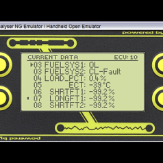
6. Usage
On program start four buttons UP/DOWN/ESC/OK are displayed. Actually, the button area is not just the displayed button, but the whole rectangular area surrounding that button. So, the display is divided into four rectangular areas that can be touched to control the menu accordingly.
Up/Down moves the cursor up/down in a menu/list or
increments/decrements a number +/-1 in a number field.
For the Up/Down areas long presses are recognized in some menus/lists.
Up/Down long press in a menu/list leads to a page scroll or
increments/decrements a number +/-10 in a number field.
OK selects a menu/list item or
toggles the state of a checkbox or
selects Yes for a Yes/No question or
changes to the next menu in a menu roll or
jumps one menu up if in the deepest menu.
ESC leaves a menu/list or
changes to the previous menu in a menu roll or
selects No for a Yes/No question.
1. Supported OBD2 Features
- supports up to 8 OBD2 capable ECUs
- database of 4277 descriptions for Diagnostic Trouble Codes (DTC)
- confirmed DTCs, OBD2 service 0x03
- pending DTCs, OBD2 service 0x07
- permanent DTCs, OBD2 service 0x0A
- current data, OBD2 service 0x01
- freeze frame data, OBD2 service 0x02
- supported PIDs for service 0x01 and 0x02: 0x00 to 0x64, 0x70, 0x80, 0x84, 0x8D, 0x8E, 0xA0, 0xC0, 0xE0
- dynamic supported PIDs for OBD2 service 0x02 (each DTC that caused freeze frame storage can have its own supported PIDs)
- evaluation and display of location of oxygen sensors, OBD2 service 0x01 and 0x02, PID 0x13 or 0x1D (this affects displayed bank/oxygen sensor indices of some PIDs)
- evaluation of tester configuration bytes, OBD2 service 0x01 and 0x02, PID 0x4F and PID 0x50 (this affects displayed maximum values and resolution of some PIDs)
- Inspection/Maintenance Readiness Code / OBD2 monitor status since DTCs cleared, OBD2 service 0x01, PID 0x01
- OBD2 monitor status of the current driving cycle, OBD2 service 0x01, PID 0x41
- Vehicle Identification Numer (VIN), OBD2 service 0x09, infotype 0x02
- Calibration IDs (CALIDs), OBD2 Service 0x09, infotype 0x04
- Calibration Verification Numbers (CVNs), OBD2 service 0x09, infotype 0x06
- ECU name, OBD2 service 0x09, infotype 0x0A
- in-use performance tracking counters for spark ignition engines and compression ignition engines prior MY2010, OBD2 service 0x09, infotype 0x08
- in-use performance tracking counters for compression ignition engines for MY2010 and beyond, OBD2 service 0x09, infotype 0x0B
Further features and more details can be found in my other OBD2 projects for the Elektor OBD2-Analyser NG and the OBD2 for Raspberry Pi project (chapter 4.4 OBD2 Diagnostic Services supported by HHGui/HHEmu).
2. Hardware Requirements
Parts used for the prototype:
- Arduino M0 Pro
- Waveshare 2.8inch TFT touch shield
- Microbot PCB Proto Shield UNO for Arduino (optional)
- Diamex Pi-OBD module + OBD2 cable
- 12V vehicle socket to USB adapter to power the Arduino via USB
(1) Arduino M0 and Arduino Zero should work as well, even if the Zero has 2 pins (Arduino pin 2 and 4) swapped compared to the M0/M0 Pro.
(2) Any other TFT touch shield working with 3.3V logic levels can be used if you are able to adapt the drivers coming with the shield to my software.
(3) Any other prototype board or no prototype board at all. That depends on the actual installation, see chapter 3.
(4) The old Diamex DXM OBD2 module is supported, too if you find a shop that still has it.
(5) The Pi-OBD module features two pins (5V, GND) to power the TFT display on the Pi. A selfmade Pi-OBD module 5V, GND pins to Arduino micro USB adapter could be used to power the Arduino. Do not try to power the Arduino at its 5V output pin! Without further protective diodes soldered in, this might destroy the regulator on the Arduino.
3. Hardware Preparation
The setup of the prototype is described here. Dependend on the actual installation you use for your handheld diagnostic tester (see chapter 3.4.2), your setup might differ.
3.1 Waveshare TFT Touch Shield
Solder 3 null Ohm resistors/jumpers on the backside of the TFT touch shield to route the SPI signals to Arduino digital pins 11, 12 and 13. I used short pieces of wire and soldered them on the jumper pads.
3.2 Microbot PCB Proto Shield UNO for Arduino
Solder the 4 pass-through connectors in that come with the shield.
Do not solder the ICSP header in!
The Microbot Proto shield is made for the UNO. On the UNO the ICSP header is connected to pins 11 MOSI, 12 MISO and 13 SCK.
The same wiring is found on the Proto shield. However, on the M0 Pro the ICSP header is connected to other pins 18, 21, 20 (SAMD21 PA12 MISO input, PB10 MOSI output, PB11 SCK output) and pins 11 PA16, 12 PA19, 13 PA17 (LED output) are used or free for other purposes. So, with the ICSP header soldered in, the Proto shield would at least shorten the PB11 and PA13 output port pins on the M0 Pro.
3.3 Wiring
Connect OBD2 module Tx to digital pin 0 that is used as Arduino Rx.
Connect OBD2 module Rx to digital pin 1 that is used as Arduino Tx.
For the first setup use 2.2 kOhm resistors in the Tx and Rx lines, so that no ports are destroyed, if you make a wiring error. In the error case a current of
I = U/R = 3.3V/2200Ohm = 1.5mA flows, that is below the SAMD21's limits.
Connect OBD2 module Ground to any GND pin, e.g. Arduino pin 14.
If the Pi-OBD Module is used, connect Pi-OBD Module Reset to Arduino pin 8.
If the Pi-OBD Module is used, connect Pi-OBD Module BIOS/Bootloader to GND (BIOS).
3.4 Installation of the OBD2 Module
3.4.1 Installation of the DXM OBD Module
For the DXM module that is easy. Due to its small size, it can be soldered/fixed on top of the prototype shield. The wiring can be found in chapter 2.1 of my other project here.
3.4.2 Installation of the Pi-OBD Module
As you can see in the images, I have just built a prototype using a breadboard. My Pi-OBD module was modified with a 2x13 pin stacking header for an update of the OBD2 for Raspberry Pi project. That header prevents an easy installation now.
If you want to build a real handheld diagnostic tester, there are at least three solutions.
Solution 1 (for experts only, yields the least stacking size)
You carefully have to make two changes to the Pi-OBD module.
First, desolder the pin header on the module or try to get one from Diamex without it.
Second, cut the PCB next to the two mounting holes on the right side of the PCB (orientation see ASCII art below).
 -------              -
|o      |            |o|
|       |            | | <-- cut here, the 5V/GND pin header should stay
|       |          --  |
|       |         |    |
|       |         |    |
|        ---------     |
|                      |
|                      |
|                      |
|          ----------  | <-- cut here
|o        |          |o|
 ---------            -
Now, the Pi-OBD module can be moved in from the left until its left PCB side (that one with the two remaining mounting holes) hits the Arduino headers. With that changes, the Pi-OBD module exactly fits under the TFT touch shield and above the prototype shield.
After soldering the wiring, attach a layer of thin isolation between prototype shield and Pi-OBD module, e.g. use hot glue.
Also take care that the condensers on the Pi-OBD module do not touch the TFT touch shield, e.g. attach isolating tape on the condensers.
For additional space, the unused ICSP header on the TFT touch shield could be desoldered.
If you do not want to make that irreversible change to your new Pi-OBD module, there are two other solutions.
Solution 2 (simplest)
Simply mount the Pi-OBD module under the Arduino. My Arduino is mounted in a case. The Pi-OBD module's mounting holes placements differ from the Arduino's mounting holes placements. If 4 additional holes are drilled into the case, the Pi-OBD mounting holes can be used to screw the Pi-OBD module to the Arduino's case. If there is not enough space between Arduino and case, use plastic screws or use hot glue to fix the Pi-OBD module to the case. Then, the Pi-OBD module's mounting holes could be used to mount the whole construction in a case.
note:
If you choose this solution and come to the idea to remove the Proto board completely (if you solder the wires from/to the Pi-OBD module right to the pins on the bottom of the Arduino), you get in trouble with the SPI.
There are two ways to fix that:
1. You can fix that if you desolder the ICSP header on the TFT touch shield.
2. You can fix that if you do not solder in the 3 null Ohm resistors/jumpers on the Waveshare TFT Touch shield and if you add the define USE_ICSP_SPI to the supplied platform.local.txt file (see chapter 4, add -DUSE_ICSP_SPI to compiler.cpp.extra_flags and compiler.c.extra_flags).
Solution 3 (biggest size)
A third more complicated solution would be to use two custom made oversized prototype boards to make more space for the Pi-OBD module in between (see ASCII art below).
This needs 2 copper strip boards for the 2 prototype shields. The strips must be cut in the middle of the boards for all strips that later contain pin headers.
So that the left side of a strip connects the left female pin headers mounted on top of a board with the left male pin headers mounted under the board and the right side of a strip connects the right female pin headers mounted on top of a board with the right male pin headers mounted under the board. The backside is the solder side, if you do not use double sided strip boards with through holes.
So, this needs two sets of four Arduino female pin headers.
One set of four Arduino male pin headers.
And one set of four Arduino male pin headers with longer pins for stacking.
All headers could be made using pin strips.
------------- TFT touch shield
| | <- TFT touch shield male pin headers
I I <- female pin headers
--------------------- custom prototype shield 1
| | <- male pin headers with stacking height
| Pi-OBD module |
I --------------- I <- female pin headers
--------------------- custom prototype shield 2
| | <- male pin headers
I I <- Arduino female pin headers
------------- Arduino
4. Software Installation
The paths used here are given for an Arduino IDE 1.8.5 installation on a Win10 PC.
The file/folder names used here refer to files/folders in the HHGuiArduino.zip archive in the Downloads section.
1. copy the HHGui directory (Arduin IDE sketch folder) and all files in it to a path of your choice
2. copy the subdirectories and all files of the libraries folder to Documents\Arduino\libraries or use the Arduino IDE library manager
3. copy the file platform.local.txt to
C:\Users\YOUR USER NAME\AppData\Local\Arduino15\packages\arduino\hardware\samd\1.6.16\This file sets some compiler flags needed to configure the HHOpen/HHGui software for the Arduino.
You could reduce DISPLAY_HEIGHT=96 in steps by 8 (8 pixels = one menu/list line) to get faster polling of a single OBD2 PID in the current data list menu.
DISPLAY_HEIGHT must be divisable by 8 without remainder.
DISPLAY_HEIGHT must not be less than 32.
DISPLAY_HEIGHT should not be less than 40. Otherwise some text is cut off.
DISPLAY_HEIGHT must not be greater than 128.
note: if you later compile other Arduino projects you should remove the platform.local.txt file to avoid troubles.
4. add libhhgui.a and its path to platform.txt (platform.txt is located under the same path than platform.local.txt, see above)
search for the line
compiler.arm.cmsis.ldflags="-L{runtime.tools.CMSIS-4.5.0.path}/CMSIS/Lib/GCC/" -larm_cortexM0l_mathcompiler.arm.cmsis.ldflags="-L{runtime.tools.CMSIS-4.5.0.path}/CMSIS/Lib/GCC/" -larm_cortexM0l_math "-LYOUR PATH\HHGui" -lhhguinote: if you later compile other Arduino projects you should undo that change in platform.txt to avoid troubles.
5. increase the Uart/Ringbuffer Rx buffer size in Ringbuffer.h
Uart/Ringbuffer uses 64 bytes of receive buffer. That is not enough to receive more than 3 OBD2 DTCs (inside the loop() function serial data is not read and copied fast enough). Change rx buffer size to 256 to fix that. Values that are not a power of 2 should be avoided, since the modulo operation to calculate the next head/tail for the ring buffer cannot be optimized by the compiler, then.
In order not to break other Arduino software, do the change in file
C:\Users\YOUR USER NAME\AppData\Local\Arduino15\packages\arduino\hardware\samd\1.6.16\cores\arduino\RingBuffer.h#ifdef HHOPEN_ARDUINO
#define SERIAL_BUFFER_SIZE 256
#else
#define SERIAL_BUFFER_SIZE 64
#endif6. if you are using the Diamex DXM module, remove or comment out the following line in HHGui.ino
#define HAS_AGV 17. compile/upload the HHGui.ino sketch with Arduino IDE v1.8.5 (other versions have not been tested by me)
5. Software Description
The software base is the OBD2-Analyser NG AT90CAN128 firmware for the DXM OBD2 module. The Pi-OBD module part (AGV) of the Raspberry Pi HHGui software has been merged into it. The result is a new OBD2 handheld firmware supporting DXM and AGV OBD2 modules.
The sketch configures a custom SPI using sercom1 with pins 11 (MOSI), 12 (MISO) and 13 (SCK). The default Arduino SAMD21 SPI using sercom4 at the ICSP header is not used. Addressed SPI slave devices are the HX8347D TFT controller, the XPT2046 touch controller and the SDCard on the Waveshare 2.8inch TFT touch shield. The SDCard's chip select is just disabled. The SDCard is not used by the project.
For accessing the TFT controller a 12Mbps SPI baud rate is used.
For accessing the touch controller a 2Mbps SPI baud rate is used.
The firmware writes its display data to a 132 x 96 LCD frame buffer. The frame buffer data is scaled by 2 and centered in the 320 x 240 TFT by the TFT driver. The display orientation of the TFT originally is 240 x 320. So, the display output additionally is rotated by +90°. See TFT.cpp
For the touch panel 8bit A/D sampling of x,y-values is used. Since only 4 touch areas have to be detected (see Usage below) that is sufficient.
The hardware x,y-values are rotated by +90° as well. Furthermore, the 8bit values are scaled to match the display dimensions. See Touch.cpp
The sketch configures the timer TC3 to generate a cyclical 10ms interrupt. 10ms interval is used to debounce the touch controller's PENIRQ signal (panel touched signal). Furthermore, the firmware uses that time tick to generate own timers.
6. Usage
On program start four buttons UP/DOWN/ESC/OK are displayed. Actually, the button area is not just the displayed button, but the whole rectangular area surrounding that button. So, the display is divided into four rectangular areas that can be touched to control the menu accordingly.
  ---------------------------
 |             |             |
 |     UP      |     ESC     |
 |             |             |
 |---------------------------|
 |             |             |
 |    DOWN     |     OK      |
 |             |             |
  ---------------------------
Up/Down moves the cursor up/down in a menu/list or
increments/decrements a number +/-1 in a number field.
For the Up/Down areas long presses are recognized in some menus/lists.
Up/Down long press in a menu/list leads to a page scroll or
increments/decrements a number +/-10 in a number field.
OK selects a menu/list item or
toggles the state of a checkbox or
selects Yes for a Yes/No question or
changes to the next menu in a menu roll or
jumps one menu up if in the deepest menu.
ESC leaves a menu/list or
changes to the previous menu in a menu roll or
selects No for a Yes/No question.
Discussion (4 comments)


EN0184678ID 2 years ago
Wonderfull project thank you
Reply
Thomas Beck 2 years ago
Thanks for the thumbs up. Unfortunately, the Pi-OBD module hardware seems no longer available. So before you waste time on my project, you better check with Diamex if they will produce another batch.
Reply
EN0184678ID 2 years ago
Is there any other hardware solution can I get like elm327 preprogrammed can to serial
Reply
Thomas Beck 2 years ago
None that I know. If you only need OBD2 on CAN, there are some CAN shields available. However, this requires a lot of programming effort and knowledge. Since this requires a lot of Flash memory you could use one of the more powerful Arduinos with onboard CAN controller. This just needs an additional CAN transceiver module and no full shield. This makes it easier to attach a display shield to the Arduino later. Another solution: If you want to use an ELM, you could use an ELM compatible Bluetooth OBD2 module like an OBDLink LX. Then you need an Arduino with onboard Bluetooth or something like an HC-05/06 module to get the data to the Arduino. This solution probably is much easier than using a CAN shield. In this case, a disadvantage is that you cannot power the Arduino through the OBD2 connector.
Reply
Show more
1 Comment(s)
Thomas Beck 6 years ago
To my surprise, Elektor has already released the German variant of my article about the text compression I use in my OBD2 projects here: https://www.elektormagazine.de/articles/kurzgefasst-texte-fur-mikrocontroller-speicher-sparen-durch-kompression
In the article it is mentioned that the source code of the compression/decompression is available in the Arduino project. This is not the case yet. It will be available before the magazine release of the article. I plan to release a version which is suitable for other projects, too. So, this still takes some time to make it more generic.
In the article it is mentioned that the source code of the compression/decompression is available in the Arduino project. This is not the case yet. It will be available before the magazine release of the article. I plan to release a version which is suitable for other projects, too. So, this still takes some time to make it more generic.
Reply
Thomas Beck 5 years ago
Here is the second version of the text compressor/decompressor. The archive contains an example how to use this. In addition to the usual bug fixes, a new feature has been implemented in step 5 of the compression that allows even a large number of texts to be compressed with 8bit indices, which in the previous version would have required 16bit indices or entropy encoding, which is not yet implemented in the demo version.
The article describing the compression method was published in the Elektor magazine January/February 2020.
The article describing the compression method was published in the Elektor magazine January/February 2020.
Reply
Thomas Beck 5 years ago
Here is a first version of the text compressor/decompressor. The archive contains an example how to use this.
In the meantime, Elektor has also published the French version of the article here:
https://www.elektormagazine.fr/articles/condense-de-textes-pour-microcontroleurs
In the meantime, Elektor has also published the French version of the article here:
https://www.elektormagazine.fr/articles/condense-de-textes-pour-microcontroleurs
Reply
Show more
2 Comment(s)

Updates from the author
Thomas Beck 4 years ago
Since the list of supported PIDs and InfoTypes on the main project page is outdated, here is the current state:
Supported PIDs (OBD2 Service 1 and 2) for M0/M0Pro/Zero, Due, Mega/Mega2560 and SparkFun FreeSoC2:
0x00 - 0x71, 0x77 - 0x7C, 0x7F, 0x80, 0x83 - 0x85, 0x87, 0x88, 0x8B - 0x8F, 0x98, 0x99, 0x9B, 0x9D, 0x9E, 0xA0 - 0xA3, 0xA5, 0xA6, 0xC0, 0xE0
Supported InfoTypes (OBD2 Service 0x09) for M0/M0Pro/Zero, Due, Mega/Mega2560 and SparkFun FreeSoC2:
0x00, 0x02, 0x04, 0x06, 0x08, 0x0A, 0x0B, 0x16 - 0x19, 0x20, 0x40, 0x60, 0x80, 0xA0, 0xC0, 0xE0
Like in the previous release, this no longer fits into Uno and Elektor Uno R4. These boards got all bugfixes plus most of the changes described below. Since this needed a lot of Flash memory, support for some PIDs had to be removed. Removed PIDs 0x78, 0x79, 0x8B, 0x98, 0x99.
Supported PIDs (OBD2 Service 0x01 and 0x02) for Arduino Uno R3 and Elektor Uno R4:
0x00 - 0x68, 0x6C, 0x6D, 0x70, 0x77 - 0x7C, 0x80, 0x84, 0x87, 0x8D, 0x8E, 0xA0, 0xC0, 0xE0
If you do not have access to the latest SAE J1979-DA standard, check https://en.wikipedia.org/wiki/OBD-II_PIDs to see the meaning of most of the PIDs and InfoTypes listed above.
Changes:
- For PID evaluation, replaced some large switch-case statements with if-else if-else statements
This needs less RAM (compiler generates no jump tables) but more Flash and function runtime is no longer nearly constant.
As a positive result, DISPLAY_HEIGHT could be increased +8 (= +1 menu/list line) for Uno R3 and Elektor Uno R4 which needed an additional 132 bytes RAM for the display frame buffer. So, these boards can display 8 menu lines now.
- added new PIDs
0x6B Exhaust Gas Recirculation Temperature, sensor A-D (wide range or normal)
0x6E Injection Pressure Control System A,B
0x6F Turbocharger Compressor Inlet Pressure, sensor A,B (wide range or normal)
0x9B Diesel Exhaust Fluid (DEF) Sensor Output (of a DEF quality sensor)
DEF Type - urea concentration too high/low, wrong fluid, proper mixture, no results available but sensor ok or unknown fluid type, no results available due to sensor fault or DEF property detection error
DEF Concentration (32.5% is ideal mixture of urea in water)
DEF Tank Temperature
DEF Tank Level
0x9D Engine Fuel Rate (and vehicle fuel rate which additionally contains fuel injected for aftertreatment)
0x9E Engine Exhaust Flow Rate
0xA1 NOx Sensor Corrected Data (bank 1-2, sensor 1-2)
PID 0x83 NOx Sensor contains raw sensor data. PID 0xA1 NOx Sensor Corrected Data contains the raw data manipulated by learned values and/or offsets.
0xA2 Cylinder Fuel Rate (of the most recent input stroke)
0xA3 Transmission Actual Gear (0-15, 0 = neutral, 1 = 1st gear or reverse) and gear ratio
0xA5 Diesel Exhaust Fluid Dosing
0xA6 Vehicle Odometer
- changed some PID acronyms and PID data to reflect changes in J1979-DA specification:
-- implemented new masks/texts for former FuelSys1/2 which now is FuelSysA,B to support two independent fuel systems which both can be two bank systems
If two bits are set in the received Fuel System A,B data, which is allowed now, the data is printed as is. So, an ECU could send two states for one bank, e.g. OL B1 OL-Drive B1, which makes no sense at all.
Valid combinations would be:
CL OL-Drive B1 or CL OL-Drive B2: system is closed-loop but one bank is open-loop, e.g. due to cylinder deactivation
OL-Fault B1 CL-Fault or CL-Fault OL-Fault B2: one bank is closed-loop but oxygen sensor fault on the other bank
-- With spark ignition engines also becoming equipped with particulate filters, the following PIDs are no longer Diesel only PIDs. Therefore, PID acronyms and PID descriptions have been renamed:
PID 0x8B: renamed Diesel Aftertreatment Status to Aftertreatment Status
PIDs 0x7A, 0x7B, 0x7C, 0x8B: renamed DPF to PF
-- added new data item Recommended Transmission Gear to PID 0x65 (0-15, 0 = neutral, 1 = 1st gear or reverse)
-- PID 0x1C OBD Requirements for Vehicle or Engine: added new OBD requirements for countries like Brasil, China, India, Korea and for heavy duty vehicles and for motor cycles
-- PID 0x51 Fuel Type: added new fuel types like, e.g. FC H2 (fuel cell utilizing hydrogen)
-- PID 0x83 NOx Sensor: added case No Results Available
- added new InfoTypes for MY2019+ vehicles
0x16 Vehicle Operation Data - Ignition Counters/Engine Run Time/Idle Time
0x17 Vehicle Operation Data Distance (traveled)/Fuel (consumed)
0x18 Vehicle Operation Data PKE/EOE - Positive Kinetic Energy/Engine Output Energy
0x19 Vehicle Operation Data PSA - Propulsion System Active Time (Total/City/Idle)
All VOD items are displayed with two values, a recent value and a lifetime value. Recent values are accumulated over the last 50 hours before VOD 0x19 Total Propulsion System Active Time Recent reaches 50 hours and resets to zero. If OBD2 service 0x04 (erase DTCs) is executed, the recent values are cleared as well.
- changed InfoType 0x08 (IPT for spark ignition engines) to reflect changes in J1979-DA specification:
added 4 additional counters for air fuel ratio imbalance monitor and (gasoline) particulate filter monitor
- changed display layout and drawing of IPT/VOD/Readiness data to use the same function
- added support for Supported InfoTypes masks 0x00 - 0xE0 (previously 0x00 only)
- changed display layout and drawing of Supported PIDs and Supported InfoTypes screens to use the same function
- added cnts as unit (for IPT menu and some items in the new VOD menus)
- increased the size of serial Rx buffer and DXM buffers to be able to receive and handle more data
8 ECU names of infoType 0x0A can be received at once from 8 ECUs
15 CALIDs of infoType 0x04 can be received from an ECU (CAN protocol), 9 CALIDs for non-CAN protocols
15 CVNs of infoType 0x06 can be received from an ECU
As a side-effect, DTC texts can be decompressed into an existing buffer and no longer need a temporary buffer on the stack.
note:
In the Arduino USART source code for the avr-core (HardwareSerial.cpp/h) atomic blocks are missing when accessing 16bit receive buffer indices for receive buffers > 256 bytes in size. Since Arduino Uno R3 and Elektor Uno R4 have not enough RAM for buffers > 128 bytes, this problem only affects Mega/Mega2560.
- adaption of HHGUI firmware USART code to Arduino USART code has been improved
- improved display of ECU info in diagnostics info area if DISPLAY_HEIGHT >= 40 (5 lines):
ECU info is presented on two lines now instead of the crowded E1*2:E8 in the OBD2 Analyser NG's small 132x32 LCD.
ECU: EcuAddr
selected ECU index / total number of OBD2 ECUs
e.g.:
ECU: E8
1/2
- improved display for long texts in min/max/avg current data screen
Very long texts use the complete display width now and are cut off on the right. This can happen for text only data items like PID 0x03 Fuel System Status and PID 0x1C Supported Emission Requirements.
- made CALID and CVN menu scrollable lists (page scroll with Up/Down, menu change between the two menus now with Ok (previous versions used Up/Down for this))
- implemented length checks for received PID data
"n/a" might be displayed for a data item in the Current Data menu and Freeze Frame Data menu if received data length is not great enough for the current data item of a PID.
- implemented support for longer CAN ISO-TP segmented messages (15 CALIDs result in 243 bytes to be transmitted over CAN)
Sequence number in the PCI is allowed to wrap to 0 now if it reaches 15 (1 .. 15, 0 .. 15, 0 .. 15).
- gui.c code cleanup to further reduce Flash memory usage
Bugfixes:
- Tester configuration bytes in PID 0x4F und PID 0x50 had no effect. So, if an ECU actually used this feature to change maximum value and resolution of Lambda, sensor voltage, sensor current, MAF or MAP, the displayed values for these data items were wrong since the configured scaling was not applied.
This was broken in the firmware since v1.11.0.
- PID 0x8C fixed 32bit overflow in O2 sensor concentration calculation (value after the floating point was totally wrong in most cases)
This bug was in the firmware since PID 0x8C was supported in v1.13.0.
- PID 0x8F normalized PM Sensor is a signed value and not a value with negative offset (definition was missing in old version of J1979-DA specification)
This bug was in the firmware since PID 0x8F was supported in v1.13.0.
- memory areas must not overlap when using memcpy() (happened for VIN, CALIDs and CVNs)
replaced memcpy() by memmove() as suggested in avr-gcc's string.h header file
- long centered texts in single current data and single freeze frame data screens were not displayed
Now they are output left-justified and cut off on the right. This can happen for text only data items like PID 0x03 Fuel System Status (only with the longer texts available since this release) and PID 0x1C Supported Emission Requirements (only text for 0x0F = "OBD OBD II EOBD KOBD" that comes with this release does not fit)
- min/max/avg/current data screen: if an error occurred during initial decoding of a data item, current value showed "n/a" but min/max/avg values showed values of previously displayed data item in min/max/avg/current data display. Now, the initial "..." is kept for min/max/avg values of the current data item.
Installation:
Detailed installation instructions for Arduino M0/M0 Pro/Zero, Due, MEGA/MEGA2560, UNO, Elektor UNO R4 and SparkFun FreeSoC2 covering hardware, software and wiring are given in file installation.txt. This file is covering installation with the Arduino IDE 1.8.12 that comes with the avr-gcc toolchain 7.3.0 installed.
I have upgraded my Arduino IDE to version 1.8.12 and use the latest SAM, SAMD21 and AVR cores. The AVR toolchain changed in IDE 1.8.10 from avr-gcc 5.4.0 (since IDE 1.8.6) to 7.3.0. This again makes problems with link time optimization which again has changed between the avr-gcc toolchain versions. So, the provided hhgui libraries for MEGA, UNO and Elektor Uno R4, which were built with avr-gcc 7.3.0, need an AVR core installed which also uses avr-gcc 7.3.0. For Elektor Uno R4, I had to switch to avr-gcc 7.3.0, too. If the project is compiled with avr-gcc 4.9.2, it does not fit into the Flash anymore.
The platform.local.txt and/or boards.local.txt files have been changed. So, if you already have built the project, in addition to the files in the HHGui folder, these files have to be updated, too.
For the Due, you have to manually increase serial Rx buffer to 1024 bytes (see installation.txt, Software Installation, step 10).
vasy vasy 4 years ago
100% Best...
br.
Thomas Beck 5 years ago
Uno, Elektor Uno R4: Update to firmware v1.12.1
all other boards: Update to firmware v1.13.1
Changes:
- added support for the following PIDs:
0x69 Commanded EGR Duty Cycle/Position and EGR Error
0x6A Commanded Diesel Intake Air Flow (IAF) Control and Relative IAF Position
0x71 Variable Geometry Turbo (VGT) Control (commanded/actual position and status)
0x7F Engine Run Time, Engine Idle Time, PTO (Power Take Off) Time
0x83 NOx Sensor (NOx concentration for up to 4 sensors)
0x85 NOx Control System
average reagent consumption
average demanded reagent consumption
reagent tank level
engine run time while NOx warning indicator is activated
0x88 SCR Inducement System Actual State/History States of last four 10000km blocks
reagent level too low
incorrect reagent
deviation of reagent consumption
NOx emissions too high
system active state (current 0-10000km block only)
distance traveled in 10000km block while inducement system active compared with total distance traveled in 10000km block
0x8C Oxygen Sensor (Wide Range) for Diesel (oxygen concentration and lambda for up to 4 sensors)
0x8F Particulate Matter (PM) Sensor Output for up to 2 sensors
sensor actively measuring
sensor regenerating
normalized output value: 0% (fully cleaned/regenerated sensor) - 100% (sensor soot load level when sensor regeneration is needed)
Bugfixes:
- fixed detection of second data byte B (corresponds with bank 3,4) in PIDs 0x06-0x09 and 0x55-0x58
This was broken in the firmware since v1.11.0.
- fixed memory alignment problem for all boards
Memory access to odd address in DTC text decompression stack freezed the SAM D21G microcontroller on Arduino M0 Pro. This could happen in DTC Summary menu -> single DTC screen. Most DTC texts but not all were affected by this.
Notes:
Since some of these PIDs contain very long text acronyms, I decided to change the display layout in the Current Data and Freeze Frame Data menus. Apart from some rare cases, all acronyms and their related data fit into a single line now.
With the new PIDs, the Current Data and Freeze Frame Data menus support 266 data items now which no longer fits into 8bit. Therefore, the list handling for lists with up to 65536 list items had to be activated for all boards besides Uno and Elektor Uno R4. This slightly increases Flash and SRAM usage for all lists.
The text compressor for compressing the PID text descriptions got an update which will be released in the comments section.
Installation:
Detailed installation instructions for Arduino M0/M0 Pro/Zero, Due, MEGA/MEGA2560, UNO and Elektor UNO R4 covering hardware, software and wiring are given in file installation.txt. This file is covering installation with the Arduino IDE 1.8.10 that comes with the avr-gcc toolchain 7.3.0 installed.
I have upgraded my Arduino IDE to version 1.8.10 and use the latest SAM, SAMD21 and AVR cores. The AVR toolchain changed in IDE 1.8.10 from avr-gcc 5.4.0 (since IDE 1.8.6) to 7.3.0. This again makes problems with link time optimization which again has changed between the avr-gcc toolchain versions. So, the provided hhgui libraries for MEGA and UNO, which were built with avr-gcc 7.3.0, need an AVR core installed which also uses avr-gcc 7.3.0.
Furthermore, the platform.local.txt and/or boards.local.txt files have been changed. So, if you already have built the project, in addition to the files in the HHGui folder, these files have to be updated, too.
Thomas Beck 5 years ago
For all other supported Arduino boards, this update can be ignored. There is no functional change. I have moved device specific timer initialization from HHGui.ino to new files devicetimer.c/h, though.
Parts used for the prototype:
1. SparkFun FreeSoC2 V11
2. Waveshare 2.8inch TFT touch shield for Arduino
3. Arduino Proto Shield MEGA-Rev3 with SPI stacking header
4. Diamex DXM or Pi-OBD module + OBD2 cable
5. 12V vehicle socket to USB adapter to power the FreeSoC2 via USB or
self made micro-USB-type-B plug to 2-pin power adapter to power the FreeSoC2 from the Pi-OBD module's 2-pin header.
Installation Instructions:
Read and follow the instructions in the SparkFun Hookup Guide V11 or V14 to make the FreeSoC2 Arduino IDE compatible (flash the board with the Arduino bootloader). I have integrated the SparkFun Arduino board package into the Arduino IDE 1.8.5. Cypress PSoC Creator is not used by the HHGui project. However, the SparkFun Arduino board package is partially created with Cypress PSoC Creator.
Set the two power switches on the FreeSoc2 to the 3.3V setting since the Waveshare 2.8inch TFT touch shield and the DXM or Pi-OBD modules need 3.3V signal levels.
Then, follow the instructions for all boards given in file installation.txt which is in the HHGuiArduino20190923.zip archive.
Notes:
The SparkFun Arduino board package is not documented. The C source code generated by Cypress PSoC Creator was compiled and put in a library Uno_Blocks.a and only the generated headers have been released by SparkFun. So, it is not possible to easily increase the UART receive buffer size or to enable the SPI double speed option. Therefore for CAN-protocols, at maximum only 5 OBD2 DTCs can be read from a single ECU which is sufficient for most cases. Furthermore, the TFT display update at 6Mbps SPI baud rate is a bit slow.
Internal Details:
The PSoC 5LP fixed function timer TMR3 is used to implement the 10ms timer needed by HHGui. TMR3 is a countdown counter which is configured to trigger an interrupt when it reaches 0 (terminal count interrupt). TMR3 is clocked by clkd_d5 which is a 100kHz clock signal. clk_d5 is Clock_2 in the generated code, see Clock_2.h and cyfitter.h in SparkFun Arduino board package folder psoc/cores/arduino.
SPI is clocked by clk_d1 which is a 12MHz clock signal. Therefore, the maximum baud rate is only 6Mbps. This is used for the TFT display. The SPI to the touch controller uses 2Mbps.
Thomas Beck 5 years ago
Used Parts:
- Arduino Proto Shield MEGA-Rev3
- Arduino stacking header 10-pin
- 2x Arduino stacking header 8-pin
- Arduino stacking header 6-pin
- ICSP stacking header 6-pin (2x3-pin)
- male pin header strip 1 row
Variant 1: permanent connections
- insulated copper strand to make 4 wires (each 10cm)
Variant 2: pluggable connections
- 90° bent (rigth angle) male pin header strip 1 row
- 4 jumper wires female to female (each 10cm)
The use of 4 different colors for the insulation of the wires later helps to distinguish the 4 connections.
Instructions:
0. check the pictures published on the main project page which show the Arduino Proto Shield MEGA-Rev3 with the placement of all headers and the wiring. The pictures show variant 2. In variant 1, the bent pin headers in the picture mark the point where the wires need to be soldered later. The pictures show my Pi-OBD module which was modified with a GPIO stacking header for the OBD2 for Raspberry Pi project. Just ignore this header.
1. solder in the Arduino and ICSP stacking headers
2. break off a row of 8 pins from the male pin header strip to get a 8-pin male pin header
3. solder the 8-pin male pin header in the first column from the right into the mounting holes numbered 39, 41 to 53. On the proto shield's PCB, each of these holes is connected to the similarly numbered mounting hole in the third column from the right. Later the Pi-OBD module is attached to this 8-pin header.
Variant 1: permanent connections
4. solder in the 4 wires to make the following connections:
- second row from the top, mounting hole numbered 0 (Rx) to third column from the right, mounting hole numbered 45 (Pi-OBD module Tx)
- second row from the top, mounting hole numbered 1 (Tx) to third column from the right, mounting hole numbered 47 (Pi-OBD module Rx)
- second row from the top, mounting hole numbered 2 to third column from the right, mounting hole numbered 43 (Pi-OBD module Reset)
- second row from the top, mounting hole labeled GND OR
second row from the bottom, one of the two mounting holes labeled GND to third column from the right, mounting hole numbered 49 OR 41 (Pi-OBD module GND)
Variant 2: pluggable connections
4. break off a row of 6 pins from the right angle male pin header strip to get a 6-pin right angle male pin header
5. solder the 6-pin right angle male pin header with the bent pins facing to the left in the third column from the right into the mounting holes numbered 39, 41 to 49.
6. break off a row of 3 pins from the right angle male pin header strip to get a 3-pin right angle male pin header
7. solder the 3-pin right angle male pin header with the bent pins facing to the bottom in the second row from the top into the mounting holes numbered 2, 1 (Tx) and 0 (Rx)
8. break off a single pin from the right angle male pin header strip
9. solder the 1-pin right angle male pin header with the bent pins facing to the bottom in the second row from the top into the mounting hole labeled GND OR
solder the 1-pin right angle male pin header with the bent pins facing to the top in the second row from the bottom into one of the two mounting holes labeled GND
10. plug the 4 jumper wires with female pin connectors to make the following connections:
- second row from the top, bent pin header numbered 0 (Rx) to bent pin header third column from the right, mounting hole numbered 45 (Pi-OBD module Tx)
In the picture, this is the yellow wire.
- second row from the top, bent pin header numbered 1 (Tx) to bent pin header third column from the right, mounting hole numbered 47 (Pi-OBD module Rx)
In the picture, this is the green wire.
- second row from the top, bent pin header numbered 2 to bent pin header third column from the right, mounting hole numbered 43 (Pi-OBD module Reset)
In the picture, this is the blue wire.
- second row from the top, bent pin header labeled GND OR
second row from the bottom, bent pin header labeled GND to bent pin header third column from the right, mounting hole numbered 49 OR 41 (Pi-OBD module GND)
In the picture, this is the black wire.
The pictures show that I have mounted several other bent pin headers (3.3V, 5V and several GNDs). This allows plugging in a level shifter BOB if an Arduino with 5V signal voltage is used (UNO, MEGA).
Other variations:
If an Arduino Due or MEGA is used, I recommend using a 1-pin header soldered into the mounting hole numbered 37 from the bottom side. This acts as a spacer, so that the 8-pin header solder side does not accidentally connect to the Due's or MEGA's female pin header.
If an Arduino Due or MEGA is used, the firmware uses Serial3. So, Arduino Rx is pin 15 and Arduino Tx is pin 14.
The 8-pin male pin header can be replaced by a right angle pin header to change the orientation of the Pi-OBD module. This might help for smaller UNO sized prototype boards, too.
Since not all pins of the 8-pin header are used, a 4-pin header is sufficient. However for stability, an 8-pin header is recommended.
The connection for the hardware reset is optional. The firmware requests a software reset during Pi-OBD module initialization.
A pull down resistor could be mounted between third column from the right, mounting hole numbered 39 (Pi-OBD module Bootloader/BIOS selection) to GND to definitely select BIOS. On my Pi-OBD module, there already is a pull down configured or mounted, so this is optional.
Update 2019/09/29:
While porting the software to the SparkFun FreeSoC2, I noticed that the Pi-OBD module reacts on the serial line even though it is not powered from an OBD2 connector. It draws a current of about 27mA from the FreeSoC2's GPIO which is directly connected to the Pi-OBD module's active LOW reset input if the GPIO is set HIGH (= no reset). Unlike other Arduino boards, this is because the FreeSoC2 can deliver up to 41mA on a single GPIO pin. Of course, this scenario should be avoided. If the Pi-OBD module is connected to an OBD2 connector, it still draws 6mA from that GPIO. So, I suggest putting a resistor in the reset line. However, this builds a voltage divider with the internal weak pull-up resistor on the Pi-OBD module. With a 1kOhm to 4.7kOhm resistor in the reset line, the current drops to less than 0.5mA if the GPIO is set HIGH. If the GPIO is set to 0 (= reset requested), the reset input of the Pi-OBD module is at around 0.5V level or less which still is interpreted as LOW. So, the external reset request is correctly detected. Furthermore, when the resistor is installed, the Pi-OBD module no longer reacts on the serial line if it is not powered from the OBD2 connector.
I have added an image showing the resistor in the reset line to the main project page. Furthermore, this image shows how the Arduino can be powered from the 5V and GND pins of the Pi-OBD module's 8-pin connector instead of the 2-pin connector. If numbering the pins of the 8-pin connector 1-8 like in the uploaded image, pin 1 or 2 are 5V and pin 3 or pin 7 are GND. The image shows the connection to Pin 2 (+5V) and 3 (GND).
If you have no resistor installed in the reset line and are powering Arduino and Pi-OBD module separately from different sources, you should always power the Pi-OBD module first from an OBD2 connector to avoid damage.
Thomas Beck 5 years ago
Changes:
- recompiled all hhgui library variants to get the OBD2-Analyser NG firmware update v1.12.0 / HHGui v3.21 update, especially:
- added support for bit-mapped PID 0x8B Diesel Aftertreatment Status
Internally, this PID provides the following data items:
Diesel Particulate Filter (DPF) regeneration status: yes/no
DPF regen type: active/passive
NOx Adsorber regen status: yes/no
NOx Adsorber desulfurization status: yes/no
Normalized trigger for DPF regen: 0 - 100.0 %
Average time between DPF regens: 0 - 65535 minutes
Average distance between DPF regens: 0 - 65535 km
- minor changes of title font and menu fonts: shorter underscore to reduce the space needed by PID acronyms
- fixed missing character 'S' in PID acronym names of long term secondary oxygen sensor fuel trim PIDs LTO2FTx -> LTSO2FTx
By the way, PID acronyms have been changed in more recent versions of the SAE J1979-DA specification. The OBD2-Analyser NG firmware still uses the old PID acronyms since these are generally shorter. Most of them are only 8 characters long which better fits with the small LC display (132 x 32).
The compressed PID text descriptions are generated with the text compressor which I have published in the comments section.
If you run out of Flash memory in your own microcontroller project which uses texts, you might want to try this. Details are published here:
German: https://www.elektormagazine.de/articles/kurzgefasst-texte-fur-mikrocontroller-speicher-sparen-durch-kompression
French: https://www.elektormagazine.fr/articles/condense-de-textes-pour-microcontroleurs
Installation:
Detailed installation instructions for Arduino M0/M0 Pro/Zero, Due, MEGA/MEGA2560, UNO and Elektor UNO R4 covering hardware, software and wiring are given in file installation.txt. This file is covering installation with the Arduino IDE 1.8.5.
If you already have built the project for IDE 1.8.5 you actually just need to do the follwing steps:
1. if you have changed the file HHGui/Obd2ModuleCfg.h, backup this file
2. replace the old HHGui Arduino project folder with the new one from the HHGuiArduino20190622.zip archive
3. if step 1 was relevant, copy the Obd2ModuleCfg.h backup file to the new HHGui folder
4. rebuild the project with IDE 1.8.5
In the meantime I have compiled the software with Arduino IDE 1.8.7 which uses avr-gcc 5.4.0 for the AVR based boards UNO and MEGA. The toolchain used by the IDE was updated in the IDE 1.8.6 release. This does not work together with the HHGui libraries for UNO and MEGA built with avr-gcc 4.9.2 of IDE 1.8.5. The reason is a different format used for link time optimization (LTO). Compilation stops with an error message "lto1.exe: fatal error: bytecode stream generated with LTO version 3.0 instead of the expected 4.1". Elektor UNO R4 is unaffected since this uses avr-gcc 4.9.2 independly from the IDE version. Actually, LTO is just needed for the UNO and especially the Elektor UNO R4 where the firmware without LTO would not fit into the small Flash memory.
Therefore, if you want to build the software for UNO R3 or MEGA1280/2560 under IDE 1.8.6 or IDE 1.8.7 or IDE 1.8.8, you need HHGui libraries built with avr-gcc 5.4.0. In this case, copy the relevant library from the HHGuiLibsIDE186_187_188.zip archive to the HHGui project folder.
UNO R3 + Pi-OBD module: hhguilib_agv_atmega328x.a
UNO R3 + DXM module: hhguilib_dxm_atmega328x.a
MEGA1280: libhhgui_mega1280.a
MEGA2560: libhhgui_mega2560.a
Note: if you have replaced an UNO R3 library and you later want to build the project for Elektor UNO R4, you must undo this change.
With this update UNO R3 and especially the Elektor UNO R4 almost run out of Flash memory. If you have adapted the software to another display which needs more Flash memory for its driver, you can try different versions of the Arduino AVR core to get it fit. For the Elektor UNO R4, integrating the UNO R4 as variant into the Arduino UNO R3, so that the gcc 5.4.0 compiler is used, helps.
HHGui Libraries for UNO and MEGA built with avr-gcc 5.4.0 (2902kb)
Thomas Beck 6 years ago
Changes:
- recompiled all hhgui library variants to get the OBD2-Analyser NG firmware bugfix release v1.11.1
Installation of the bugfix:
If you already have built the project for IDE 1.8.5 you actually just need to do the follwing steps:
1. replace the libraries in the HHGui Arduino project folder with the new ones from the HHGuiLibsIDE185_firmware1111.zip archive
2. rebuild the project with IDE 1.8.5
In the meantime I have compiled the software with Arduino IDE 1.8.7 which uses avr-gcc 5.4.0 for the AVR based boards UNO and MEGA. The toolchain used by the IDE was updated in the IDE 1.8.6 release. This does not work together with the HHGui libraries for UNO and MEGA built with avr-gcc 4.9.2 of IDE 1.8.5. The reason is a different format used for link time optimization (LTO). Compilation stops with an error message "lto1.exe: fatal error: bytecode stream generated with LTO version 3.0 instead of the expected 4.1". Elektor UNO R4 is unaffected since this uses avr-gcc 4.9.2 independly from the IDE version. Actually, LTO is just needed for the UNO and especially the Elektor UNO R4 where the firmware without LTO would not fit into the small Flash memory.
Therefore, if you want to build the software for UNO R3 or MEGA1280/2560 under IDE 1.8.6 or IDE 1.8.7 or IDE 1.8.8, you need HHGui libraries built with avr-gcc 5.4.0. In this case, copy the relevant library from the HHGuiLibsIDE186_187_188_firmware1111.zip archive to the HHGui project folder.
UNO R3 + Pi-OBD module: hhguilib_agv_atmega328x.a
UNO R3 + DXM module: hhguilib_dxm_atmega328x.a
MEGA1280: libhhgui_mega1280.a
MEGA2560: libhhgui_mega2560.a
Note: if you have replaced an UNO R3 library and you later want to build the project for Elektor UNO R4, you must undo this change.
HHGui libraries for Uno R3, MEGA/MEGA2560 and IDE1.8.6/7/8 (2887kb)
Thomas Beck 6 years ago
This project update adds a new submenu which displays minimum/maximum/average/current sensor data. Furthermore, even more OBD2 parameter IDs (PIDs) are supported whose sensor data is displayed in the Current Data and Freeze Frame Data menus.
Changes:
- recompiled all hhgui library variants to get the OBD2-Analyser NG firmware update v1.11.0 / HHGui v3.20 update, especially:
- implemented new submenu for the Current Data menu which displays minimum/maximum/average and current value of a data item
This helps to find defective sensors or can be used as trip computer.
The average data calculation uses the same scaling to get the display value as is used for the current data value. I.e., that the average value changes with the step size that is specified in SAE J1979/ISO 15031-5 for this data item. The average value is calculated by the formula "sum of all received current data values/number of current data values". Then, scaling is applied to get the display value. Since the project does not use float or double data types to save Flash, the scaled display value, which might be a floating point value but internally is represented by two decimal values (value before and after the floating point), is not used for calculation. Average calculation stops if the sum of all received current data values or the number of samples reaches max uint32_t.
To activate the Min/Max/Avg Current Data menu, press the OK-key in the Current Data Large Single Data screen. Then, pressing the Up/Down-key scolls to the previous/next data item in the Min/Max/Avg Current Data menu. To go back to the Single Data screen, press the OK-key or ESC-key. If the menu is entered or if the data item is changed, calculation starts again. This is indicated by three dots "..." being shortly displayed before the first calculation has finished.
If the current data item is a text-only data item, a dash "-" is displayed for min/max/avg and a text is displayed for the current value. If the text does not fit into the display, it is cut off.
For simplicity, min/max/avg is even calculated for data items for which it makes no sense at all, e.g. "time since engine start" or "distance traveled while MIL is activated" or constant values like "engine reference torque".
During implementation of the new submenu, scaling of received values to display values has been optimized in code size. Therefore, the new menu and all other changes are available for UNO R3 and Elektor UNO R4, too.
- added support for further bit-mapped PIDs (first data byte is configuration bit mask that tells the diagnostic tester which sensors are actually available)
0x65 - Auxiliary Inputs/Outputs:
power take off status
automatic transmission neutral/drive status
manual transmission neutral/gear status
glow plug lamp status
0x66 - Mass Air Flow sensor data: 2 sensors A,B
0x67 - Engine Coolant Temperature: 2 sensors 1,2
0x6C - Commanded Throttle Actuator Control and Relative Throttle Position: actuator A,B and position A,B
0x6D - Fuel Pressure Control System: commanded/actual fuel rail pressure A,B and fuel rail temperature A,B
0x77 - Charge Air Cooler Temperature: supports 2 banks each with up to 2 sensors
0x87 - Intake Manifold Absolute Pressure: 2 sensors A,B
- fonts got some kind of proportional spacing for about 25 combinations of two characters
Installation:
Detailed installation instructions for Arduino M0/M0 Pro/Zero, Due, MEGA/MEGA2560, UNO and Elektor UNO R4 covering hardware, software and wiring are given in file installation.txt. This file is covering installation with the Arduino IDE 1.8.5.
If you already have built the project for IDE 1.8.5 you actually just need to do the follwing steps:
1. if you have changed the file HHGui/Obd2ModuleCfg.h, backup this file
2. replace the old HHGui Arduino project folder with the new one from the HHGuiArduino20190228.zip archive
3. if step 1 was relevant, copy the Obd2ModuleCfg.h backup file to the new HHGui folder
4. rebuild the project with IDE 1.8.5
In the meantime I have compiled the software with Arduino IDE 1.8.7 which uses avr-gcc 5.4.0 for the AVR based boards UNO and MEGA. The toolchain used by the IDE was updated in the IDE 1.8.6 release. This does not work together with the HHGui libraries for UNO and MEGA built with avr-gcc 4.9.2 of IDE 1.8.5. The reason is a different format used for link time optimization (LTO). Compilation stops with an error message "lto1.exe: fatal error: bytecode stream generated with LTO version 3.0 instead of the expected 4.1". Elektor UNO R4 is unaffected since this uses avr-gcc 4.9.2 independly from the IDE version. Actually, LTO is just needed for the UNO and especially the Elektor UNO R4 where the firmware without LTO would not fit into the small Flash memory.
Therefore, if you want to build the software for UNO R3 or MEGA1280/2560 under IDE 1.8.6 or IDE 1.8.7 or IDE 1.8.8, you need HHGui libraries built with avr-gcc 5.4.0. In this case, copy the relevant library from the HHGuiLibsIDE186_187_188.zip archive to the HHGui project folder.
UNO R3 + Pi-OBD module: hhguilib_agv_atmega328x.a
UNO R3 + DXM module: hhguilib_dxm_atmega328x.a
MEGA1280: libhhgui_mega1280.a
MEGA2560: libhhgui_mega2560.a
Note: if you have replaced an UNO R3 library and you later want to build the project for Elektor UNO R4, you must undo this change.
HHGui Libraries for UNO and MEGA built with avr-gcc 5.4.0 (2886kb)
Thomas Beck 6 years ago
To install the bugfix, copy the supplied HHGui.ino file from the HHGuiBugfix20181224.zip archive over the file from the previous 2018/12/06 update and rebuild the project in the Arduino IDE.
Furthermore, I have added 2 new images to the main project page. These are showing a self made micro-USB-type-B plug to 2-pin power adapter to power an Arduino with micro USB-B port from the Pi-OBD module's 2-pin header. In the OBD2 for Raspberry Pi Labs project, this header is used to power the official Raspberry Pi 7" display. The TS2596 step-down DC-DC converter on the Pi-OBD module has a 5V/3A power output. This is strong enough to power any Arduino + display. With this adapter I got rid of the vehicle 12V power socket to USB adapter + USB cable and the whole solution is powered from the OBD2 connector. Well, at least for the Arduinos with micro-USB port. For the other Arduinos with USB-B port like UNO R3 and MEGA another adapter is needed.
The 90° bent micro-USB-type-B plug is not so easy to find. Here is the source I have used: Sertronics
Thomas Beck 6 years ago
Changes:
- recompiled all hhgui library variants to get the OBD2-Analyser NG firmware update v1.10.0 / HHGui v3.10 update, especially:
- added support for new bit-mapped PIDs (first data byte is configuration bit mask that tells the diagnostic tester which sensors are actually available)
0x68 - Intake Air Temperature: supports 2 banks each with up to 3 sensors
0x78 - Exhaust Gas Temperature (EGT) bank 1: up to 4 sensors, 1 - 4
0x79 - Exhaust Gas Temperature bank 2: up to 4 sensors, 1 - 4
0x7A - Diesel Particulate Filter (DPF) bank 1: delta/inlet/outlet pressure
0x7B - Diesel Particulate Filter bank 2: delta/inlet/outlet pressure
0x7C - Diesel Particulate Filer bank 1/2: inlet/outlet temperature
0x98 - Exhaust Gas Temperature bank 1: up to 4 sensors, 5 - 8
0x99 - Exhaust Gas Temperature bank 2: up to 4 sensors, 5 - 8
PIDs 0x68, 0x78 and 0x7A are supported by Ford EcoSport. I have tested the firmware with a gasoline engine. Nevertheless, Diesel PID 0x7A is reported as supported by the EcoSport's engine control module (ECM). Of course, inside the PID the configuration byte reports all sensors as unsupported. So, in the Current Data menu the firmware correctly displays all 3 pressure sensors as not available.
- error handling has been improved in the Reading Data screen when reading supported PIDs 0x20, 0x40, 0x60, ...
Error handling for the first supported PID 0x00 was already implemented.
If PIDs 0x20, 0x40, 0x60, ... are read (due to the previous supported PID mask reporting this PID as supported) and the OBD2 module answers with "NO DATA", an error message is displayed and reading of further data is stopped. Otherwise, with incorrect supported PIDs mask set, the Current Data menu might display dupplicate/wrong data items. There is no automatic retry. The user must press the ESC-key to return to the Main menu and then, the protocol can be selected again.
- text compression for DTC texts and PID long texts has been significantly improved
Due to better PID long text compression, the new PIDs still fit into an Arduino UNO or Elektor UNO R4.
Bugfix:
- incorrect data was displayed for EVAP system vapor pressure of PID 0x32 and PID 0x54 (a vehicle/ECU supports none or just one of these)
While implementing the signed DPF delta pressure of PIDs 0x7A and 0x7B, I noticed that the signed EVAP system vapor pressures of PID 0x32 and PID 0x54 were not correctly implemented. These PIDs mistakenly got a negative offset (as is correct for most other PIDs that use negative values) instead of the signed implementation requested in the SAE J1979/ISO 15031-5 specification.
Known problems with new bit-mapped PIDs:
The PID acronym sometimes is too long to fit into the Current Data/Freeze Frame Data list view.
Most classic PIDs use only 8 characters for the acronym. Surplus characters are not printed to the display. Up to now this has not been a problem since the truncated acronym still differed for all data items. Unfortunately, this is no longer the case for data items of DPF PIDs. For example, DPF1_OUTP (DPF bank 1 outlet pressure) and DPF1_OUTT (DPF bank 1 outlet temperature) are both displayed as DPF1_OUT in the list view if the last character is cut off. However, in the title line of the Current Data single data screen, there is more space. So, the full acronym is displayed there.
Installation:
Detailed installation instructions for Arduino M0/M0 Pro/Zero, Due, MEGA/MEGA2560, UNO and Elektor UNO R4 covering hardware, software and wiring are given in file installation.txt. This file is covering installation with the Arduino IDE 1.8.5.
If you already have built the project for IDE 1.8.5 you actually just need to do the follwing steps:
1. if you have changed the file HHGui/Obd2ModuleCfg.h, backup this file
2. replace the old HHGui Arduino project folder with the new one from the HHGuiArduino20181206.zip archive
3. if step 1 was relevant, copy the Obd2ModuleCfg.h backup file to the new HHGui folder
4. rebuild the project with IDE 1.8.5
In the meantime I have compiled the software with the latest Arduino IDE 1.8.7 which uses avr-gcc 5.4.0 for the AVR based boards UNO and MEGA. The toolchain used by the IDE was updated in the IDE 1.8.6 release. This does not work together with the HHGui libraries for UNO and MEGA built with avr-gcc 4.9.2 of IDE 1.8.5. The reason is a different format used for link time optimization (LTO). Compilation stops with an error message "lto1.exe: fatal error: bytecode stream generated with LTO version 3.0 instead of the expected 4.1". Elektor UNO R4 is unaffected since this uses avr-gcc 4.9.2 independly from the IDE version. Actually, LTO is just needed for the UNO and especially the Elektor UNO R4 where the firmware without LTO would not fit into the small Flash memory.
Therefore, if you want to build the software for UNO R3 or MEGA1280/2560 under IDE 1.8.6 or IDE 1.8.7, you need HHGui libraries built with avr-gcc 5.4.0. In this case, copy the relevant library from the HHGuiLibsIDE186_187.zip archive to the HHGui project folder.
UNO R3 + Pi-OBD module: hhguilib_agv_atmega328x.a
UNO R3 + DXM module: hhguilib_dxm_atmega328x.a
MEGA1280: libhhgui_mega1280.a
MEGA2560: libhhgui_mega2560.a
Note: if you have replaced an UNO R3 library and you later want to build the project for Elektor UNO R4, you must undo this change.
HHGui Libraries for UNO and MEGA built with avr-gcc 5.4.0 (2970kb)
Thomas Beck 6 years ago
Parts used for the OBD2 for Arduino UNO prototype:
1. Arduino UNO R3
2. Waveshare 2.8inch TFT touch shield for Arduino
3. Arduino Proto Shield MEGA-Rev3 with SPI stacking header
4. Diamex DXM or Pi-OBD module + OBD2 cable
5. SparkFun logic level converter BOB-11978 5V <-> 3.3V for Rx/Tx pins of 3.3V OBD2 module
The free second Tx channel of this BOB is used to level shift the Reset input pin of the 3.3V OBD2 module
7. 12V vehicle socket to USB adapter to power the Arduino via USB
Parts used for the OBD2 for Elektor UNO R4 prototype:
1. Elektor UNO R4 (3.3V setting enabled)
2. Waveshare 2.8inch TFT touch shield for Arduino
3. Arduino Proto Shield MEGA-Rev3 with SPI stacking header
4. Diamex DXM or Pi-OBD module + OBD2 cable
5. 12V vehicle socket to USB adapter to power the Arduino via USB
Detailed installation instructions for Arduino M0/M0 Pro/Zero, Due, MEGA/MEGA2560, UNO and Elektor UNO R4 covering hardware, software and wiring are given in file installation.txt.
Changes:
- recompiled all hhgui library variants to get the OBD2-Analyser NG firmware update v1.9.1 / HHGui v3.00 update, especially:
- added vehicle's "inspection/maintenance readiness status since DTCs cleared" to the diagnostics info area and made the info area available in the I/M Readiness menu, too
The info area shows a new line "RDY: Y" (I/M readiness status: Ready = Yes) or "RDY: N" (I/M readiness status: Ready = No)
notes:
When the diagnostics info area is in display (Diagnostics menu, Trouble Codes menu or I/M Readiness menu) it displays a static status.
When the I/M Readiness menu or one of its submenus is in display, PID 0x01 alternating with PID 0x41 is polled every second. This might lead to a change of MIL icon or readiness state in the diagnostics info area as soon as the menu is changed. However, the Rescan OBD2 Data menu item must be selected to get a new consistent status.
Bugfix: fixed buffer overflow if receiving 3 Calibration IDs
Read the corresponding OBD2-Analyser NG v1.9.1 / HHGui v3.00 project update description for details.
- added Arduino UNO/Elektor UNO R4 specific code for timer and SPI configuration (actually, this is the same code like for the MEGA/MEGA2560 variants)
This is automatically activated if UNO or Elektor UNO R4 board is selected in Arduino IDE.
- added hhgui library variants libhhgui_agv_atmega328x.a and libhhgui_dxm_atmega328x.a
For the UNO/Elektor UNO R4 variants, the hhgui library had to be splitted into an AGV variant and a DXM variant to save Flash memory.
- added boards.local.txt for AVR boards: one file for UNO and MEGA/MEGA2560, one file for Elektor UNO R4
This file configures an Arduino IDE 'OBD2 Module' tools menu item to select AGV (Diamex Pi-OBD module) or DXM (Diamex DXM OBD2 module).
Dependent on the selections made in the tools menu, different compiler flags and hhgui library variants are configured for the build process.
- changed/added platform.local.txt for AVR boards: one file for UNO and MEGA/MEGA2560, one file for Elektor UNO R4
This file overwrites the recipe.c.combine.pattern of the platform.txt file to add the correct hhgui library variant to the linking process.
The UNO/Elektor UNO R4 with 2 KByte RAM / 32 KByte Flash memory has not enough memory for all features of HHGui.
OBD2 features which are supported by UNO R3 and Elektor UNO R4:
- supports up to 4 OBD2 capable ECUs (*)
- confirmed DTCs, OBD2 service 0x03
- pending DTCs, OBD2 service 0x07
- permanent DTCs, OBD2 service 0x0A
- current data, OBD2 service 0x01
- freeze frame data, OBD2 service 0x02
- supported PIDs for service 0x01 and 0x02: 0x00 to 0x64, 0x70, 0x80, 0x84, 0x8D, 0x8E, 0xA0, 0xC0, 0xE0
- dynamic supported PIDs for OBD2 service 0x02 (each DTC that caused freeze frame storage can have its own supported PIDs)
- evaluation and display of location of oxygen sensors, OBD2 service 0x01 and 0x02, PID 0x13 or 0x1D (this affects displayed bank/oxygen sensor indices of some PIDs)
- evaluation of tester configuration bytes, OBD2 service 0x01 and 0x02, PID 0x4F and PID 0x50 (this affects displayed maximum values and resolution of some PIDs)
- supports erasing of DTCs, OBD2 monitors and further diagnostic data
- displays vehicle's "inspection/maintenance readiness status since DTCs cleared"
(*) If more than 4 ECUs respond to the initial 'Get supported PIDs' OBD2 request, the 4 ECUs with the fastest response will win, responses of additional ECUs will be discarded. A warning "Too many ECUs" will pop up in the Reading Data screen for 4 seconds to inform the user about the problem.
The following features of OBD2 for Arduino have been removed or have been restricted for the Arduino UNO and Elektor UNO R4:
- display size is restricted to 132 x 56 simulated pixels to reduce the frame buffer size in SRAM (1 title line + 6 menu/list lines)
- supports only 4 ECUs instead of 8 ECUs to save SRAM
- Rx buffer size is 128 bytes instead of 256 bytes to save SRAM (less DTCs can be read)
- no description for diagnostic trouble codes (no DTC Summary single data screen), just the code is displayed for a DTC to save Flash memory (**)
- only 16 DTCs instead of 48 DTCs can be stored and displayed (the actual maximum number also depends on the number of ECUs that respond)
- no OBD2 InfoTypes are read:
- Protocol Info menu has no Supported InfoTypes screen
- Select ECU menu does not show ECU names, just ECU addresses are shown
- Vehicle/ECU Information menu just shows O2 sensor locations submenu if the current ECU supports PID 0x13 or 0x1D
- no Inspection/Maintenance Readiness menu
(**) The Windows, Ubuntu or Raspberry Pi variant of HHGui could be used to get the description for a code (see description for command line option "dtc=Xxxxx", e.g. in the HHGui v2.81 update of the OBD2 for Raspberry Pi project).
vasy vasy 6 years ago
Thomas Beck 7 years ago
Parts used for the OBD2 for Arduino MEGA2560 prototype:
1. Arduino MEGA2560 Rev3 (clone)
2. Waveshare 2.8inch TFT touch shield for Arduino (read warning below!)
3. Arduino Proto Shield MEGA-Rev3 with SPI stacking header
4. Diamex Pi-OBD module + OBD2 cable
5. SparkFun logic level converter BOB-11978 5V <-> 3.3V for Rx/Tx pins of 3.3V OBD2 module
6. 1kOhm/2kOhm voltage divider for Reset pin of 3.3V OBD2 module
7. 12V vehicle socket to USB adapter to power the Arduino via USB
Detailed installation instructions for Arduino M0/M0 Pro/Zero, Due and MEGA/MEGA2560 covering hardware, software and wiring are given in file installation.txt.
Warning about missing level shifting for some input signals on Waveshare shields
Since the MEGA uses 5V logic levels, the TFT touch shield must support 5V logic levels, too. The Waveshare 2.8inch TFT touch shield has level shifters for SPI onboard and is advertized to support 5V Arduinos like UNO and Leonardo. However, level shifting for all chip select lines and the TFT data/command selection pin is missing. After reading the data sheets of TFT display controller and touch controller, I think that this should be fixed. Details are given in file installation.txt.
Changes:
- added Arduino MEGA specific code for timer and SPI configuration
This is automatically activated if MEGA/MEGA2560 board is selected in Arduino IDE.
- added hhgui library variants libhhgui_mega1280.a and libhhgui_mega2560.a
However, the OBD2-Analyser NG firmware in all hhgui library variants is unchanged. Therefore, the supported OBD2 features are still as given in chapter 1 on the main project page and OBD2 for Arduino is still showing version number 1.9.0 at startup.
- added platform.local.txt for MEGA/MEGA2560
This file overwrites the recipe.c.combine.pattern of the platform.txt file to add the correct hhgui library variant to the linking process.
- minor bugfix for all OBD2 for Arduino variants: added code in KEY_EventHandler() for special case touch detected via PENIRQ but no valid position data read
This prevents detection of a long press without having detected a short press before.
In the context of this change the code for touch detection has been changed.
Known Problems:
I have measured the duration of the display update for MEGA2560 with 16 MHz master clock and 8MHz SPI clock to access the TFT display. The display update takes about 276ms, measured with millis() called before and after LCD_UpdateDisplay() in HHGui.ino. I have added a list of measurements for different Arduino boards and different SPI baud rates to TftTouchShieldCfg.h.
The faster the TFT display update, the better the responsiveness to touches on the touch panel. This is very important in HHGui menus in which a permanent display update takes place, e.g. in the current data menu. While a touch can be detected during a display update via the PENIRQ pin, the touched position cannot be read via SPI during a display update. So, a faster display update increases the chance that valid touch data still can be read after the update.
Level shifting for signals from/to OBD2 module
Since the MEGA uses 5V logic levels, the Arduino's output pins to the OBD2 module's Rx and Reset input pins must be level shifted 5V to 3.3V.
The OBD2 module's Tx output pin could be connected to the Arduino Rx input pin without level shifting. However, I do not recommend that. I have lost count how often I have swapped Rx/Tx by mistake. And this will be fatal. So, I recommend using a level shifter for input and output signals like the SparkFun logic level converter BOB-11978 (that uses a voltage divider 10kOhm/20kOhm in 5V to 3.3V level shifting direction and a BSS138 MOSFET in 3.3V to 5V level shifting direction) or even better its successor BOB-12009 (that uses BSS138 for both level shifting directions).
For the Reset pin you might have to change the voltage divider on the BOB-11978. On the Pi-OBD module there is a pull-up configured that prevents pulling the signal to ground if the resistor values used for the divider are too great. In my case (the internal pull-up for the reset pin of the Cortex M0 on the Pi-OBD greatly varies) they are to great. You could change the values on the BOB or you could build a divider yourself. A voltage divider made up of 1kOhm/2kOhm resistors worked for me. I successfully tried that for the Rx pin, too. However, I suggest to try greater values to reduce the current. The formula is R1 = R2 = R3 if using 3 resistors or R1 = 0.5 * R2 if using 2 resistors for the divider.
Example: R1=R2=R3=1kOhm (R2=R3 can be replaced with a single 2kOhm resistor)
Thomas Beck 7 years ago
Parts used for the OBD2 for Arduino Due prototype:
1. Arduino Due (clone)
2. Waveshare 2.8inch TFT touch shield for Arduino
3. Arduino Proto Shield MEGA-Rev3 with SPI stacking header
4. Diamex Pi-OBD module + OBD2 cable
5. 12V vehicle socket to USB adapter to power the Arduino via USB
Detailed installation instructions for Arduino M0/M0_Pro/Zero and Due covering hardware, software and wiring are given in file installation.txt.
Changes:
- added Arduino Due specific code for timer and SPI configuration
This is automatically activated if Due board is selected in Arduino IDE.
- the OBD2 module and the serial device used to communicate with it can be configured via the new configuration file Obd2ModuleCfg.h
- the TFT touch shield variant and the SPI used to communicate with the SPI slave devices on it can be configured via the new configuration file TftTouchShieldCfg.h
This file also contains information about the different variants of the Waveshare 3.2/3.5/4inch TFT touch shields.
- additional TFT frame buffer drivers are provided in ILI9341.cpp/h for the Waveshare 3.2inch TFT touch shield and in ILI9486.cpp/h for the Waveshare 3.5/4inch TFT touch shields
For the 3.2inch shield with TFT display size 240 x 320, the 96 x 132 LCD display frame buffer coming from the libhhgui.a is doubled for output (like it is done for the 2.8inch shield).
For the 3.5/4inch shields with TFT display size 320 x 480, the 96 x 132 LCD display frame buffer coming from the libhhgui.a is trippled for output. The display update of the 3.5/4inch shields is slower, due to the larger amount of display data that must be transmitted via SPI.
- renamed TFT class to TFTFB class (TFT frame buffer) to avoid compiler warning about ambiguity with the Arduino TFT library
- decreased minimum touch pressure threshold XPT2046_MIN_PRESSURE in touch panel driver file XPT2046.cpp
The minimum touch pressure value that must be read from the panel helps to filter out touch release and slight touches.
While adding support for the 3.2/3.5/4inch TFT touch shields, I discovered that after warm-up of the panel, the read pressure value significantly decreases in some areas of the panel, sometimes falling below the threshold used up to now. The same happens to the read position values.
- made the OBD2 module Reset pin available for the Diamex DXM OBD2 module, too
- connecting the OBD2 module Reset pin is optional, now. You can leave that pin open. However, I recommend to use the Reset pin.
On both Diamex OBD2 modules there is a pull-up resistor mounted/configured that pulls the input high to disable reset.
The software has been changed to send an initial software reset command, if the serial connection to the module hangs at startup.
- connecting the OBD2 module BIOS/Bootloader pin to GND (= selecting BIOS) is optional. You can leave that pin open.
On both Diamex OBD2 modules there is a pull-down resistor mounted/configured that pulls the input low to select BIOS.
- libhhgui.a comes in two variants now, one for M0/M0 Pro/Zero as libhhgui_samd21.a and one for Due as libhhgui_sam3x8e.a
However, the OBD2-Analyser NG firmware in libhhgui_xxx.a is unchanged. Therefore, the supported OBD2 features are still as given in chapter 1 on the main project page and OBD2 for Arduino is still showing version number 1.9.0 at startup.
- the file platform.local.txt has been changed to overwrite the recipe.c.combine.pattern of the platform.txt file to add the correct libhhgui_xxx.a to the linking process
Therefore, this file comes in two variants now, one for M0/M0 Pro/Zero and one for Due.
- editing platform.txt is no longer necessary
So, other Arduino projects can be build if just the platform.local.txt file is removed.
- sequence of pin initialization has been made independent from Arduino initialization functions
While porting the project to Arduino Due, I discovered that initializing pins in constructors that initialize global objects must not be done. For the current Arduino M0/M0 Pro/Zero source in main.cpp it works because __libc_init_array() is called after init(). init() contains the default pin initialization and __libc_init_array() calls the constructors. So, the sequence is correct. However, for the Arduino Due things are different. Here main.cpp calls init() and init() calls __libc_init_array() before it disables the pull-ups on every pin via digitalWrite(pin, LOW). So, here the desired pin configuration is destroyed.
- the SDCard chip select pin misconfiguration bugfix released on the main project page a few days ago is done via pin defines in the TftTouchShieldCfg.h file, now
While porting the project to Arduino Due, I found a serious bug in SDCard.h. A missing 'static' in front of the SDCard chip select pin number constant lead to misconfiguration of SD chip select pin 5 as pin 0 (constructor is called before constant is initialized). As a result pin 5 just got the default configuration of Arduino M0 Pro init() function in wiring.c: input without pull-up/down. Since the TFT touch shield has a pull-up mounted for signal line SD_CS, SD_CS is pulled high (= chip deselected). Exactly that is the desired behaviour, so the error heals itself. Instead of pin 5 serial Rx pin 0 is misconfigured as output high before a call to Serial1.begin() in the Arduino setup() function heals that, too. However, for a very short time during initialization two outputs are connected. So, you see, it is always wise to add those current limiting resistors in the Tx/Rx lines I mentioned in chapter 3.3 of the main project page ;)
Notes for users who already have built the project for M0/M0 Pro/Zero:
If you already have built the project for the M0/M0 Pro/Zero according to the information and code provided on the main project page, you must at least apply the bugfix I have released on the main project page a few days ago! However, due to the other improvements described above, I recommend updating according to the new installation instructions in file installation.txt.
- the SPI default for M0/M0 Pro/Zero has changed from pins 11, 12 and 13 to ICSP header
While porting the project to Arduino Due, I used the Arduino Proto Shield MEGA-Rev3 for the M0 Pro, too. So, changing the default to SPI via SPI/ICSP header saved me from having to change the configuration file every time when switching boards.
This configuration can be changed in the new configuration file TftTouchShieldCfg.h.
- the default for the OBD2 module reset pin has changed from 8 to 2, since the Waveshare 3.2/3.5/4inch TFT touch shields use pin 8 for TFT reset.
This configuration can be changed in the new configuration file Obd2ModuleCfg.h.
- since editing platform.txt is no longer necessary, undo the changes in platform.txt and just use and edit the new platform.local.txt from M0_Pro_Zero\platform.local.txt
Notes about Waveshare 3.2/3.5/4inch TFT touch shields:
The Waveshare 3.2/3.5/4inch TFT touch shield support is experimental because I just had the first version of those shields for testing and I no longer had these shields when porting the project to the Due. You might have to change the display orientation or other register initialization to your needs.
There are at least two versions of each of those shields. The first batch of the shields works with 3.3V logic levels only. The first batch is missing the 74VHC125 level shifter. Furthermore, the first batch is missing the backlight control pin. Additionally, several condensers have been added to the second batch. Therefore, try to get the version with level shifters, additional condensers and backlight pin.
The 4inch shield, at least the first batch of it without backlight control, needs an external power supply. The voltage regulator on the Arduino UNO or Arduino M0 Pro is not strong enough to power it. Therefore, the 4inch shield has not been tested with the OBD2 for Arduino project. Since the backlight of the second batch can be regulated by PWM, the second batch might work without separate power supply, if the backlight is dimmed.
The larger shields become quite hot. As a result, the data acquired from the touch panel is subject to a significant thermal drift. However, the center of the panel still returns quite stable touch data. So, another touch panel data acquisition strategy might be necessary to reliably detect Up/Down/Esc/Ok presses.