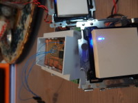
One I/O-pin for led and switch. Led don't goes out. [140040-I]

In this circuit the LED and switch are both connected with the same I/O pin. But the led stays burning when the switch is operated. Only 3 resistors are used. One common wire is going to every switch and one contact wire for every switch. So you don't have any extra wire! The led's are fading in the video, but can be used for several things.
In this circuit the LED and switch are both connected with the same I/O pin. But the led stays burning when the switch is operated. Only 3 resistors are used. One common wire is going to every switch and one contact wire for every switch. So you don't have any extra wire! The led's are fading in the video, but can be used for several things. The special thing is that the led's stay working when the switch is operated, this is normally not the case ! See the demo: http://www.youtube.com/watch?v=-sPYhgat7Ys&feature=youtu.be
In a domotica system the led can be used for several things. For example when deterctors are registering movement outside, the leds (in the switch) in the main bedroom go on and off.
08/09/2013
I have expanded the code so the leds and relais can be controlled over RS485. Now for example the Raspberry Pi can be used to control the relais or to control the leds on the switches via a html page on the pi.


Discussion (0 comments)