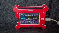
Part 4 : GROW platform - data logger software

New data logger firmware for the GROW gardening monitoring IoT platform
Related projects
- Part 1: Protect your sensor boards (BMP280, SI7021, etc.)
- Part 2: GROW radio platform nRF24+ multi-sensor
- Part 3: GROW data radio visio logger TFT 3.5"
- Part 4: GROW platform - data logger software
- Part 5: Your Grow data on ESP8266
New code
- Low level NO contact.
- NC contact, if alarm ON
- Display and menu to the size of the screen.
- Creation of an associated library for the TFT LCD
- Treats negative temperatures (display and mini max)
What the logger code does:
At startup, if the object is not on time, you arrive on the date time setting page.
As soon as the logger is adjusted in time, it starts with a search for sensors, then, next, displays the radio data.
the object is on time, it starts with an initialization display sequence
SD card search, radio sensor search
the sensors found are listed and the object switches to basic display mode.
If no radio reception, a beep buzzer and base display with green band "No radio reception"
The buzzer beeps every x seconds (according to MUTE_ALERTE (180000) // the time is xmn between buzzer alerts)
-> Alarm request ON (BP + Logger maintained for approx. 4s), logger issues the request, the probe must respond, if ok, Logger BEEP BEEP
If at the end of the delay, no response from the probe, the logger retransmits the request
-> Alarm request OFF (BP- Logger maintained for approx. 4s), logger sends the request, the probe must respond, if ok, Logger BIP BIP BIP
Low level alert, the probe issues the alert, the logger must validate reception. If ok, the logger displays the low level info with a sky blue band.
If not ok, the probe retransmits the alert.
When the high level returns, the probe transmits the info to the logger, the logger must respond and clear the low level message.
To avoid multiple messages during handling or filling, we count the NO contact info (low level) and we act according to the counter.
Door open alert, if the alarm is activated, ISR INT0 (pin D2) on the probe is active. If a detection takes place,
the probe sends an alert message, if there is no return from the logger, at the end of the timeout, it sends the message back.
If the logger has received the alert, beep beep beep beep and door open alert is displayed with a red stripe.
If BP sdReboot, we enter a code function for the state sd yes, no. No SD detection by switch
If BP menu, you enter the adjustment menu:
1: Instructions (minimum maximum alert thresholds)
2: SD timeout, data recording periodicity on SD card
3: Setting the date and time
4: Display the summary of the eeprom (setpoint, sd time, alarm state on off)
// FR
demande d'alarme ON (BP + Logger maintenu pendant environ 4s), le Logger envoie la demande, la sonde doit répondre, si ok Logger BEEP BEEP
Si à la fin du délai, aucune réponse de la sonde, le logger retransmet la requête
demande d'alarme OFF (BP- Logger maintenu pendant environ 4s), le logger envoie la demande, la sonde doit répondre, si ok Logger BIP BIP BIP
Alerte niveau bas, la sonde émet l'alerte, le logger doit valider la réception. Si tout va bien, l'enregistreur affiche les informations de bas niveau sur un fond bleu.
Sinon, la sonde retransmet l'alerte.
Lorsque le niveau haut revient, la sonde transmet l'information à l'enregistreur, l'enregistreur doit répondre et effacer le message de niveau bas.
Pour éviter plusieurs messages lors de la manipulation ou du remplissage, nous comptons les coordonnées no et nous agissons en fonction du compteur.
Alerte porte ouverte, si l'alarme est activée, ISR INT0 (broche D2) est actif. Si une détection a lieu,
la sonde envoie un message d'alerte, s'il n'y a pas de retour du logger, à la fin du timeout, elle renvoie le message.
Si l'enregistreur a reçu l'alerte, un bip bip bip bip et une alerte porte ouverte s'affichent sur fond rouge.


Discussion (0 comments)