Simple audio power amplifier
Download the Elektor article below.
It all started with the Measurement Filter for Class D (100540-1) published in issue 415, July/August 2011. It was designed to handle large output signals, up to 70 V (RMS!). We never came around to really test the filter at the highest levels. A completely discrete high voltage amplifier design was started with 23 high voltage transistors (MJE340, MJE350, MPSA42 and MPSA92) working with a split power supply of +/- 110 V. This design got a bit out of hand. Even a PCB for a first prototype was designed but then one thinks ‘all this just to test a filter?’ The amplifier should be able to deliver a signal with extreme low distortion up to 20 kHz at 70 V. The impedance of the filter is 1 kΩ minimal, so 100 mA peak output current is necessary (more would be preferable). Looking for an alternative like an integrated circuit that can handle these high output voltages we came across the LME49811 from Texas Instruments. The title of the datasheet ‘Audio Power Amplifier Series High Fidelity 200 Volt Power Amplifier Input Stage with Shutdown’ was inviting to have a closer look. The specifications are excellent. Although one thing is not entirely clear from the datasheet. Are the measurements made according to the Test Circuit which omits the entire output stage? No examples are mentioned for the output stage. Another strange thing is the missing of the bottom layer of the Demonstration Board Layout which is visible in an older version of National Semiconductor from 2008. But we still went ahead and designed an amplifier with this component.
One of the most important properties for the possible candidates for the power transistors (T4/T5) in the output stage is a very wide safe operating area. Eventually we found some very nice ones from Semelab Limited, the MG6330-R (NPN) and its complementary MG9410-R. At 200 V across collector and emitter more than 600 mA of collector current may flow. This will be the case when the amplifier is driven to maximum output swing with no load. A wide class A setting in an class AB output configuration is now possible. The DC current gain versus collector current is almost constant up to several amperes (a little less for the PNP version) contributing to a linear output stage. Similar demands are valid for the drivers (T2/T3) of the power transistors. The MJE15032 (NPN) and MJE15033 (PNP) can handle 250 V maximum and the DC current gain is also reasonably constant with changing collector current. Both drivers and power transistors have high transition frequencies: 30 MHz for the MJEs, 60 MHz for the MG6330-R and 35 MHz for MG9410-R. For the quiescent current control an ordinary BD139 is used.
At first the design was meant for our July/August edition. But then one of our editors asked ‘Who needs this kind of amplifier?’ Can it not be used as an ordinary audio power amplifier? Yes of course it can, but not without a few additions and modifications. At a lower power supply voltage the output stage is able to deliver a lot of power to a speaker! Quiescent current can be 3 A at 120 V across. To keep it a simple amplifier we assume the amplifier is going to be connected to speakers with standard impedances from 4 Ω to 8 Ω, where 3 Ω is considered to be the lowest allowable impedance. At a power supply of +/-60 V and a 3 Ω load the output transistors will be driven outside their DC safe operating area but stay well within the 100 ms curve. For that reason we advise to use a 2 x 40 V transformer. We used a cheap 500 W version with a regulation that could be better. In practice this means a higher supply voltage without load or when little output power is delivered. With a lower mains voltage (224 instead of 230!) we measured around +/-56.8 V DC in our test setup. As a precaution a Zobel network is added (R13/C5). This network ensures the amplifiers stability in case there is no load. It also helps when the load is highly inductive. Inductor L1 is an extra protection against capacitive loads. Resistor R12 dampens any ringing or resonance that may occur. On the PCB R12 is placed inside L1, this is only done to save space.
Apart from the output stage the LME49811 only needs a few components to complete the amplifier. With the value chosen for the feedback resistor, should one of the power supply voltage (60 V max.) be present at the output, the maximum dissipation will not be more than the maximum specified by its manufacturer. In our case that’s a little under 0.25 W. This results in 15 kΩ for R4. To give the amplifier the correct gain we take into account a maximum output swing of 5 V below the power supply voltage. At 60 V DC this means 55 V peak. Over the past years at Elektor we dimension our amplifiers to deliver their maximum undistorted output power (THD+N = 0.1 %) at 1 V input level. Any modern day preamplifier is able to supply this level. In our case the gain is exactly R4/R3, taking R1 and R2 into account. This means an E-12 value of 390 Ω for R3 (15k/(55/Ö2)). To keep common mode suppression of the input stage of the LME49811optimal the impedance of R1//R2 should be the same as R3//R4. So the values of R1 and R2 are the same as R3 and R4 respectively. The input impedance is approximately 15 kΩ which is also no problem for preamplifiers. The low cut off frequency is determined by C1, in our case theoretically 2.2 Hz. C2 limits the bandwidth of the input signal to suppress HF noise and limit too fast input signals. This will partially reduce slew rate of the amplifier. This is the case when for instance at the input a perfect rectangular signal is present. For compensation only a single capacitor is needed (C3). To make experimenting easy we used a trimmer with PTFE as a dielectric, which is also an excellent choice for audio. The PCB is also suitable for silvered mica capacitors with a lead spacing of 5.9 mm. While testing we noticed the value of C3 can be much less than 30 pF. Adjusting the trimmer to the lowest level, the amplifier remained stable. But we noticed no improvement of measuring results when the capacitor was adjusted below 1/3 of its maximum value. So set it at 1/3 (approximately 18 pF). To avoid any DC voltage at the output we added a DC servo (IC2). It compares the output voltage with ground and corrects the input of the LME49811 (pin 4) with a very small current. The correction is done at the non-inverting input because of the higher impedance of the resistors. R2 is 15 kΩ and at pin 5 the impedance is only 380 Ω (R3//R4). The small current compensates any input offset of IC1 and bias current of pin 4. The control speed is a few tens of a second. That’s why the output relay takes a little longer to activate. The opamp used is a OPA177 and has excellent DC specification. Its own bias current and offset are maximally 2.8 nA and 60 µV. So the largest offset voltage at the output of the power amplifier is caused by the bias current of IC2 through R14. Worst would be an offset of 0.6 mV. When our prototype was stabilized (no output signal) the output voltage was around 0.2 mV only.
Let’s hope the amplifier will never fail, but any electronic circuit will eventually stop working. The junction temperature of the audio power transistors is often driven above 70 °C and that will reduce the life span of the semiconductors. Our experience is failing semiconductor usually becomes a short circuit. If no fuse is blown this means a DC voltage at the output of the amplifier. A DC protection is something no audio power amplifier should go without. After power-up the amplifier needs a few seconds to settle. Like most power amplifiers the speaker is connected to the output by way of a relay. Three conditions must be met before the relay will activate. No DC voltage must be present at the output of the amplifier. Of course the power supplies must be present. In our case the positive power supply is used to power the relay. The negative power supply is not monitored. The last one is the presence of the secondary transformer voltages. If these are not present the relay is immediately deactivated to prevent a DC level over the speakers before it will occur. To prevent a ground loop an optocoupler. D3, D4 and C14 rectify the transformers voltage to a DC level. R19 makes sure, should the mains transformer get switch of or its fuse blown, the voltage over de led inside the optocoupler decreases rapidly to a level at which the opto transistor is no longer active. This in turn will activate T6. Capacitor C16 is then discharged and this in turn will deactivate the relay driver stage. The time constant of C16 and R25//R26 determines the time it takes to activate the relay when the amplifier is turned on (in practice one and half times, so 6 seconds).
The relay is a 48 V version, but the power supply voltage is about 56 V. To limit the voltage over the relay only a small resistor is needed in series with the coil. At 48 V the coil of relay needs only a few mA’s to activate, 8.7 mA to be precise. At 56 V a resistor of 1 kΩ/0.25 W will do. The tolerance of the energizing voltage of a relay is rather large. So even if the supply voltage drops the relay will stay energized. The release voltage is a lot lower than the operate voltage. The release voltage of the relay we used (RT314048) is 10 % of its nominal voltage, so 4.8 V. The operate voltage is 70% of its nominal value, so 33.6 V. If the 48 V relay is difficult to get also a 24 V relay can be used. The energizing current is almost double as high and the dissipation of the series resistor thus a lot higher. The coil resistance of a RT314024 relay is 1440 Ω. In this case a 2 kΩ resistor will have to be used, 2.2 kΩ will also do. The dissipation will be a little over 0.5 W and a 1 W resistor is needed. While designing the PCB we already gave R29 a big enough footprint. Should another manufacturer’s relay be used, the value of R29 can be different of course. In all this the voltage drop of about 1 V across T10 is being neglected. The current through led D6 is also being neglected. With a 48 V relay this current is a mere 0.35 mA. The protection circuit is calculated for the high voltage of 56 V. The operating voltage of the LME49811 ranges from +/-20 V to +/- 100 V. At a lower supply voltage some resistors have to be changed. This is also true for the feedback resistors, when the input sensitivity should remain the same. The gain should be lower at lower supply voltages. The minimum gain of the LME49811 is 20 (26 dB). So in our view the gain at a supply voltage of +/-20V this gain would give a too high sensitivity. The DC protection is basically just two transistors and a low pass filter. The time constant of 3.3 seconds of RC network R23/C15 is maybe a bit long but, the higher the DC voltage the faster T7 or T8 will discharge C16. If a positive DC offset is present at the output greater than 0.55 V the C16 will be discharged enough by T8 to deactivate the relay. If the output is negative T7 will discharge C16. Because the negative current through R23 is directly responsible for discharging C16 the sensitivity is less than with a positive offset.
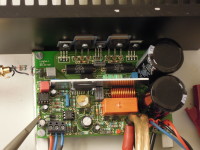
The decoupling of the power supply is done by way of large electrolytic capacitors with low ESR. These were originally meant as smoothing capacitors in the high voltage amplifier design, so no external ones had to be used. For an audio power amplifier it is critical that the power supply lines leading to the PCB don’t produce any interfering magnetic fields that can increase distortion by inducing currents in feedback loops and other parts of the amplifier. One way to suppress this unwanted effect is tying the three power supply lines close together and decouple the power lines as close as possible at the power stage. On the PCB the power supply tracks have single rectified currents flowing, because of the class AB output stage. By trying to keep the corresponding positive and negative tracks as close as possible together the produced magnetic field is almost sinusoidal and causes les distortion. On a double sided PCB these tracks can be on opposite sides. These design considerations are important for power amplifiers with very low distortion figures. Also a star ground is a must, to be found at C5. Here input ground, feedback, Zobel network, loudspeaker ground and power supply ground come together. So the PCB is specifically designed for a mono amplifier. For a stereo amplifier simply build two.
The opamp for the DC correction has its own +/-15 V power supply, derived from the main supply by way two resistors, two zener diodes and decoupling capacitors (R17/R18/D1/D2/C12/C13). In case a lower power supply voltage is used the value of R17 and R18 has to be reduced. Also take into account that from the positive 15 V the enable current (R5) for IC1 is taken. This current is 1.47 mA. The voltage at pin 1 of IC is in our case 2.92 V (a value not to be found in the datasheet). In principle the biasing of de +15 V is maybe to low but it is sufficient. The supply current of the OPA177 is 1.3 mA and the enable current is 1.47 mA. Together this is more or less the same as R17 delivers (2.78 mA at 56.8 V). The main supply voltage can drop because of excessive output power. At 233 W sine-wave power to a 4 Ω load the power supply was only 48.9 V. In this case the current through R17 is only 2.26 mA. But the enable current of IC1 may be as low as 1 mA and the supply voltage of IC2 is much higher than needed. The most important function of D1 and D2 is to make sure the power supply voltage of IC2 is never higher than +/-15 V. In our prototype the output of IC2 was not even 1.1 V. Power supply rejection of IC2 and the additional filtering by C11 make sure that the quality of the amplifier is never influenced. The typical bias current of the LME49811 is 100 nA, the maximum is not specified. We measured less than 37 nA. Additionally the maximum input offset is 3 mV. So in worst case the offset correction needs to compensate 4.5 mV of total input offset voltage. For IC2 this means a maximum output voltage of 6 V ((4.5mV/15kΩ)*20MΩ). Should a higher voltage than 6 V occur something is not in proper working order.
The maximum power dissipation of IC1 is almost proportional with its power supply, although the
power supply current increases slightly with increasing power supply voltage. From the datasheet we derived that at +/-60 V the maximum supply current is 18 mA. This is independent of any input signal. So
the power dissipation of IC1 is in our case a little over 2 W (2.16 W at 120 V total). As a heat sink we used a simple 2 mm thick aluminum plate. Calculating the thermal resistance is not that difficult. De datasheet states the thermal resistance from junction to case is 0.4 °C/W and using a thermal compound tha thermal resistance from case to heat sink approximately 0.2 °C/W. Let’s make that a total of 0.8 °C/W, just to be safe. Total dissipation is about 2.16 W. If we want the driver to have a long life we advise to keep the junction below 70 °C. In an enclosure the ambient temperature will be higher than the surrounding room temperature, let’s say 40 °C. That makes the necessary resistance from junction to ambient 30 °C/2.16 W = 13.8 °C/W or lower. The thermal resistance of the heat sink should be 13 °C/W. If we search the internet (but not too long) for a formula or graph to find out how big the aluminum plate should be we came across 2 formulas and a graph. The first formula 500/A (A in cm2, both sides) resulted in a necessary surface of 19 cm2 (size). The second formula 50/ÖA (A in cm2) gives a surface of 14.8 cm2 which is substantially smaller. We had to extrapolate the graph. For a plate of 2 mm thick the curve ends at a surface of 30 cm2 (Rth = 7.9 °C/W). Extrapolation to 20 cm2 gives a thermal resistance of 9.5 °C/W. Our plate of 2.5 by 8 cm will be sufficient, no matter what solution to believe. We measured the temperature of the heat sink. At a room temperature of 20 °C the heat sink became 49 °C. With a power dissipation of 2.16 W this means our heat sink effectively has a thermal resistance of 13.5 °C/W. Components like L1 and C8/C9 limit convection somewhat and thus the thermal resistance of the plate will be higher. The PCB is designed to give the plate just enough room, from C10 to C8/C9. Mount the plate to IC1 with enough distance from the PCB so it won’t come in contact with R1, R5 and R4. Bend L1 a little from the heat sink. Important: the metal part of the backside of IC1 is connected to the negative supply voltage. If only a thermal compound is used between heat sink and IC there is a big chance the heat sink is also connected to the negative supply voltage, in our prototype it was!
An important part of any power amplifier is the heat sink for the power transistors. How large should it be? This amplifier is able produce a lot of power with only 1 set of power transistors. Usually with this amount of power two pairs are used at least. More transistors in parallel would increase efficiency of the amplifier. Especially at 4 Ω loads the two emitter resistors of 0.2 ohm are responsible for a loss of 5 % alone. Two extra power transistors would increase the size of the PCB and we wanted to keep this a small (the PCB at least) and simple amplifier, but with very good specifications none the less. We found a compromise in a heat sink from Fischer Elektronik. Not exactly small but to ensure no thermal runaway will occur with high output power a very low thermal resistance is necessary. At a height of 100 cm its resistance is 0.7 °C/W. An example: we measured the efficiency of the amplifier with a regulated DC voltage of +/-56.8 V. In a 4 Ω load the amplifier will deliver 299 W at a distortion of 0.1 %. Now the efficiency is 68.5 % and the loss of the amplifier 137 W. Most power will be dissipated in the large heat sink. Without extra measures its temperature wood rise more than 90 °C above ambient if a pure sine-wave signal is used continuously! Also the emitter resistors R10 and R11 (5 W resistors) will be strained to their maximum and when the output is clipping may be even beyond that. But with music the real power will of course be substantially less, in the heat sink and R10 and R11. When testing we use a large tangential blower to avoid damaging the power amplifier.
Construction of the amplifier depends for a large part on the enclosure that is going to be used. For testing we attached two metal bars to the heat sink to mount the PCB on. This way no mechanical stress is applied to transistors in the output stage. The PCB should be mounted against the heat sink so the pins of the transistor are as close to their respective pads on the PCB as possible. The pins get a double bend. The first bend should be as close to the transistors packadge as possible. Never bend de legs directly but put a metal plate against the pins to avoid micro fractures in the packadge. These can reduce the lifespan of the transistors. The second bend is where the holes in the pads are. The insulation of the transistor can be placed between transistor and heat sink before locating the exact position for the second bend. But that isn’t too critical except when ceramic insulators are used, they really make a difference. After this is done there will be no thermal stress as well. The transistors are mounted firmly on the heat sink after the PCB is already mounted (don’t forget the insulating pads). Only then the pins of the transistors can be soldered. Most components can be soldered before all of this is done, except for IC1 and the power supply capacitors C8 and C9. They are mounted and soldered after placement of the power transistors is finished. The heat sink of IC1 will be in front of the screws of the transistors of the power stage. Leaving the power supply capacitors to the end will give a clearer view when mounting the power transistors. IC1 is the last component to be mounted at this point (or earlier) the exact placement of the aluminum plate and the holes for the mounting of IC1 can now be determined (2.5 cm high and 8 cm long). As stated earlier, leave enough space between the PCB and the heat sink to avoid contact with parts that are the closest to it. To really rule out a possible short circuit to the heat sink, a fitting insulating pad can be placed in-between IC1 and its heat sink. This doesn’t change the total thermal resistance that much. Mount the aluminum plate onto IC1 before soldering IC1 to the PCB. This will avoid mechanical stress to the pins of IC1. For connecting the speaker and the power supply mounting tabs with two pins are used (faston, 6.3 x 0.8 mm lead spacing 5.08 mm). Most terminal blocks can’t handle currents over 5A or so. Peak currents in the speaker output and power supply can be close to three times as high. The relay used is rated 16 A. A last detail concerns the construction of L1. L1 is made of 13 windings of 1.5 mm (diameter) enamelled copper wire wound on a 7 mm drill. Leave the endings long enough to mount the inductor with a little distance from the PCB. The endings of the inductor should be in line with the center of the inductor. Resistor R12 is then placed inside L1 and its connecting wires bend to correspond with the pads on the PCB. Place the two components simultaneously on the PCB and look if the resistor remains in the center of the inductor and the inductor a little distance from the PCB before soldering the four wire endings.
Before connecting the amplifier directly to the power supply the quiescent current of the output stage needs to be set. We advise as a precaution to put two 47 Ω/5 W power resistors in series with the PCB power supply connections (in plus and minus). Should something be wrong (a short circuit somewhere) chance is the amplifier itself will not be damaged but in worst case the two power resistors will burn out. The use of a regulated power supply would be better but who has access to a dual power supply that can be set to +/- 56 V or so. Before switching on the power supply turn P1 fully counter clockwise. Current consumption in the positive power line should be about 30 mA (with activated output relay). Screw terminal K7 should be connected to the transformer of the power supply. Put an ampere meter in series (with the power resistor) and turn P1 slowly clockwise until the current increases 30 mA, resulting in a reading of 60 mA. This low setting is more than enough. If the temperature of the heat sink rises the quiescent current will also rise slightly but should stay below 90 mA. At high power output the temperature of the junctions of the two power transistors T4 and T5 will rise a lot more than the temperature of the heat sink and thus VBE multiplier T1 will not compensate this fully. Momentarily the quiescent current will rise to several 100 mA, but will fall when power is reduced and the heat sink cools down again. In this the amplifier has a nice extra. You could say the class A setting of the output stage rises with the supplied output power.
Measured performance
Power supply: mains transformer 2 x 40 V/500 VA (Nuvotem 0500P1-2-040), 4 x 10000 µF/100V
Input sensitivity 0.88 V (137 W/8 Ω, THD+N = 0.1 %)
0.91 V (145 W/8 Ω, THD+N = 1 %)
Input impedance 15 kΩ
Sine-wave power 137 W (8 Ω, THD+N = 0.1 %)
145 W (8 Ω, THD+N = 1 %)
220 W (4 Ω, THD+N = 0.1 %)
233 W (4 Ω, THD+N = 1 %)
Peak/Music power 218 W (8 Ω, THD+N = 10 %)
(+/-56.8 V DC power supply) 175 W (8 Ω, THD+N = 1 %)
165 W (8 Ω, THD+N = 0.1 %)
395 W (4 Ω, THD+N = 10 %)
316 W (4 Ω, THD+N = 1 %)
299 W (4 Ω, THD+N = 0.1 %)
Power bandwidth (50 W/8 Ω) 2.1 Hz…125 kHz
Slew rate 26.7 V/µs
Rise time 2.4 µs
Signal to noise ratio >94 dB (B = 22 Hz…22 kHz linear)
(Referred to 1 W/8 Ω) >97 dBA
Harmonic distortion plus noise 0.0033 % (1 kHz, 1 W, 8 Ω)
(B = 80 kHz) 0.0006 % (1 kHz, 50 W, 8 Ω)
0.006 % (20 kHz, 50 W, 8 Ω)
0.0047 % (1 kHz, 1 W, 4 Ω)
0.0009 % (1 kHz, 100 W, 4 Ω)
0.009 % (20 kHz, 100 W, 4 Ω)
Intermodulation distortion 0.002 % (1 W, 8 Ω)
(50 Hz :7kHz = 4 :1) 0.0009 % (50 W, 8 Ω)
0.003 % (1 W, 4 Ω)
0.0026 % (100 W, 4 Ω)
Dynamic IM distortion 0.0033% (1 W, 8 Ω)
(3.15 kHz square wave + 0.0022 % (50 W, 8 Ω)
15 kHz sine wave) 0.0045 % (1 W, 4 Ω)
0.0027 % (100W, 4 Ω)
Damping factor 560 (1 kHz, 8 Ω)
311 (20 kHz, 8 Ω)
DC protection +0.55 V/-0.86 V
DC output offset 0.2 mV (0.6 mV theoretically max.)
Delay output relay 6 s
Efficiency 8 Ω 70 .6 % (THD+N = 0.1 %)
(DC power supply) 72.5 % (THD+N = 1 %)
4 Ω 68.5 % (THD+N = 0.1 %)
70.5 % (THD+N = 1 %)
We also recorded some plots. Pictures tell more than numbers?
Plot A shows measurements of harmonic distortion and noise at output levels 1 W and 50 W into an 8 Ω load with a bandwidth of 80 kHz. The plot at 1 W is mainly noise (THD+N = 0.0034 %). Only at the end towards 20 kHz the distortion slightly rises above noise (THD+N = 0.0052 %). At 50 W (this is 20 V so you can compare it with the datasheet of the LME49811) the noise floor is relatively lower in comparison to the output level. We now can see that distortion is starting earlier, because the noise floor is lower. At 1 W this is masked by the noise. The distortion at 20 kHz is almost similar as the figure at 1 W. A plot at 100 W is not that much different from the plot at 50 W. The figures can differ a bit with temperature and time. At these low levels 0.005 or 0.006 % is not something to worry about, just very good.
Plot B shows distortion plus noise as a function of output level at 1 kHz with an 8 Ω load and a bandwidth of 22 kHz. The reduced bandwidth will show better the onset of increase in distortion. As you can see the distortion of the output signal remains extremely low while the noise floor relatively sinks with the increase of the output level. At 127 W the linear operation ends and the clipping point is reached. Distortion will rise quickly with the increase of the output level now. A THD plus noise of 0.1 % is considered a just level to still speak of a clean and undistorted signal. This is reached at a level of 137 W. If we really overload the amplifier to 10 % distortion the output power is than 174 W. A remark must be made here however. The transformer we used is a cheap 500 VA type (it’s almost impossible to find a smaller transformer with 2 x 40 V) but its regulation is not that good. At 10 % THD the power supply voltage decreased to +/-51.5 V. With increase of output power distortion will rise even more quickly.
Plot C shows a Fourier analysis of a 1 kHz signal at 50 W (20 V) with an 8 Ω load. The residual spectrums of the power supply ripple as well as the harmonics of 1 kHz are at levels that are simply inaudible. The 3rd harmonic is at a level of -113.8 dB. That’s 2 ppm. Do we need to say more…Total harmonic distortion plus noise is at this level 0.0006 % (bandwidth is 80 kHz).
Bill of Materials
Resistor
R1,R3 = 390 Ω, 5%, 0W25
R2,R4,R17,R18,R22,R23,R30 = 15 kΩ, 5 %, 0W25
R5 = 8kΩ2, 5 %, 0W25
R6,R20,R28 = 1kΩ2, 5 %, 0W25
R7 = 220 Ω, 5 %, 0W25
R8,R9 = 100 Ω, 5 %, 0W25
R10,R11 = 0Ω2, 1 %, 5 W, low inductance, Vishay Dale LVR05R2000FE73
R12,R13 = 3Ω9, 5 %, 5 W
R14 = 220 kΩ, 5 %, 0W25
R15,R16 = 10 MΩ, 5 %, 0W25
R19 = 27 kΩ, 5 %, 0W25
R21 = 470 kΩ, 5 %, 0W25
R24 = 1 MΩ, 5 %, 0W25
R25,R26 = 820 kΩ, 5 %, 0W25
R27 = 68 kΩ, 5 %, 0W25
R29 = 1 kΩ, 5 %, 0W25
P1 = 470 Ω, 20 %, 0W15, trimmer, top adjust
Capacitor
C1 = 4µ7, 10 %, 63 V, MKT, lead spacing 5/7.5 mm
C2 = 1 nF, 10 %, 400 V, MKT, lead spacing 5/7.5 mm
C3 = 5-57 pF, 250 V, trimmer, top adjust, Vishay BCcomponents BFC280908003
C4,C6,C7 = 100 nF, 10 %, 100 V, lead spacing 5/7.5 mm
C5 = 47 nF, 10 %, 400 V, lead spacing 5/7.5 mm
C8,C9 = 4700 µF, 20 %, 100 V, lead spacing 10 mm, snap-in, diam. 30 mm
Panasonic ECOS2AP472DA
C10 = 2u2, 10 %, 63 V, lead spacing 5/7.5 mm
C11 = 33 nF, 10 %, 63 V, lead spacing 5/7.5 mm
C12,C13,C16 = 10 µF, 20 %, 100 V, lead spacing 2.5 mm, diam. 6.3 mm
C14 = 1 uF, 20 %, 250 V, lead spacing 2.5 mm, diam. 6.3 mm
C15 = 220 uF, 20 %, 16 V, lead spacing 5 mm, diam. 10 mm, bipolar
Inductor
L1 = 450 nH, 13 windings, 7 mm inner diam. 1.5 mm enamelled copper wire
Semiconductor
D1,D2 = 15V, 0W5, zener
D3,D4 = 1N4004
D5 = 1N4148
D6 = Led red 3 mm, through hole
T1 = BD139
T2 = MJE15032
T3 = MJE15033
T4 = MG6330-R
T5 = MG9410-R
T6-T10 = 2N5550
IC1 = LME49811TB/NOPB
IC2 = OPA177GPG4
IC3 = 4N25
Other
K1 = 2-way pinheader SIL, straight, pitch 2.54 mm
K1 = 2-way socket SIL, straight, pitch 2.54 mm
K2-K6 = Faston, through hole, lead spacing 5.08 mm
K7 = 3-way PCB terminal block, pitch 5 mm
RE1 = Relay, PCB, SPCO, 16 A, 48 V/5.52 kΩ, TE Connectivity/Schrack RT314048
T1-T3 = thermal pad TO-220, Kapton MT Film, 0.15 mm, 6 kV,
T4,T5 = thermal pad TO-3P, Kapton MT Film, 015 mm, 6 kV,
T2,T3 = Bush 3 mm, TO-220
Heat sink 0.7 °C/W, SK 47/100 SA
Misc.
PCB 110656-1 v1.0


Discussion (37 comments)
MMuller 5 years ago
MMuller 5 years ago
TonGiesberts 5 years ago
Markus Dreiling 6 years ago
I made a video of the problem you can watch there: https://youtu.be/8J7fcn5oeUQ
Kind regards
Markus
Quenton 6 years ago
I made another 10 Ohm earth loop breaker of the Rod Elliott variety. Used one between each electronic ground and the earth (PE) (also chassis). Dual redundant diodes in case of short circuit.
The very faint buzz from the bass cone is now completely eliminated.
Now there is 20 Ohms isolation between the left and right channels.
Q.
Markus Dreiling 6 years ago
luchenbe 6 years ago
Markus Dreiling 6 years ago
Thank you for sharing you solution.
luchenbe 6 years ago
dsc-9122.jpg (1140kb)
luchenbe 6 years ago
luchenbe 6 years ago
I think Elektor should address this problem, as almost all stereo amplifiers have a single supply and hence have solved this hum problem.
Luc Henderieckx
luc.henderieckx@telenet.be
TonGiesberts 6 years ago
Markus Dreiling 6 years ago
Today i tested this ground breaker: http://sound.whsites.net/earthing.htm
And i tested to connect both input grounds to the 0V GND as Pascal Hilbon writes.
But sadly, both not helps.
I read the german version of elektor and i understood that you recommend to use two separate power supplies, but i thought that it´s not needed.
Any further ideas or is there a way how i could possible modify the circuit to use both amplifiers with one power supply? Or how to fix the problem?
Many thanks for you help
Quenton 6 years ago
Still, from my research I think an earth loop breaker (per channel) would fix this.
Pascal Hibon 6 years ago
Also, try to kep all wiring as short as possible and at a good distance from the transformer.
TonGiesberts 6 years ago
Quenton 6 years ago
Sounds like an earth loop, with current circulating between left and right channels.
I have similar problem although I think lower level, and I think it can be fixed with two earth loop breakers to isolate (10R) each Q-Watt from the other and from the chassis (except in case of short-circuit).
I have not yet modified my own... it's on my to-do list.
I think large traffo can induce a voltage differential in the case which can cause current e.g to flow causing buzz. Rod Elliott has tips for a 10 Ohm ground loop breaker, but most people use it between the amp and connected source.
Like you, I am definitely getting an earth loop buzz left-right within the system (with inputs connected).
John Walker 7 years ago
Calpe 7 years ago
It's been running everyday, for numerous hours , I'm very happy with the built its quality.
See also post 616 here
http://www.diyaudio.com/forums/chip-amps/301100-watt-project-62.html#post5338787
q-watt-front-view.jpg (749kb)
q-watt-rear-view.jpg (656kb)
John Walker 7 years ago
http://www.diyaudio.com/forums/chip-amps/301100-watt-project-7.html
http://www.diyaudio.com/forums/chip-amps/301100-watt-project-29.html
Peterphuket 7 years ago
Before I used the 2 mono mosfet blocks from ALBS, a German brand from 200W each, for many years, and was rather skeptical about the Elektor design.
But I want to offer the ALBS for sale now, they are history.
Calpe 7 years ago
Ignore all comments by a 'Andrew'
http://www.diyaudio.com/forums/chip-amps/301100-watt-project.html
Quenton 7 years ago
Two rectifier are disconnected, unused. Just never removed them. Lazy bones...
The PCB is an ESP P39 soft start to limit the current into the transformers to about 10A for 0.1 seconds. Then you can use a 2.5A fuse. The soft start has its own (6VA?) 9V transformer peeping out.
This photo was at 98% complete... before I tidied up.
img-20170525-wa0003.jpeg (999kb)
John Walker 7 years ago
Quenton 7 years ago
Sounds good even at low levels ~0.1Watts.
Q.
Pascal Hibon 7 years ago
Enjoy the built!
John Walker 7 years ago
So i orderded the kits!
Kind Regards
John
Calpe 7 years ago
Shadders 7 years ago
Yes, the kit is recommended since the IC LM49811 is discontinued.
Regards,
Richard.
Pascal Hibon 7 years ago
Calpe 7 years ago
http://www.farnell.com/datasheets/972841.pdf?_ga=2.120345611.2077625043.1516967163-2008272732.1489653076
2SA2223A
https://www.digikey.co.uk/products/en?keywords=2SA2223A
Calpe 7 years ago
You can replace MG9410-R with 2SA2223A, 2SA2223A-Y, MAG9413, MAG9413B, MG9411-R"
Also try https://www.utsource.net/sch/2SA2223A
TonGiesberts 7 years ago
Calpe 7 years ago
Just did a Google search and found this:-
http://www.el-component.com/bipolar-transistors/mg9410-r
Pascal Hibon 7 years ago
I've been wondering about C15. Isn't the 16 volts a bit low for this condensor. Supose there goes something wrong with the amp and it outputs the minus voltage rail. The voltage divider made up of R21 and R22 is not going to protect C15. The voltage across C15 will be around minus 54 volts; and this will immediatly kill the condensor.
As for C16; as T7 will conduct, C16 will get a high negative voltage across it pins. Should C16 not be a bipolar condenser as well?
Or am I missing something?
Sarbjit Singh Mal 6 years ago
Calpe 7 years ago
The DC protection is basically just two transistors and a low pass filter. The time constant of 3.3 seconds of RC network R23/C15 is maybe a bit long but, the higher the DC voltage the faster T7 or T8 will discharge C16. If a positive DC offset is present at the output greater than 0.55 V the C16 will be discharged enough by T8 to deactivate the relay. If the output is negative T7 will discharge C16. Because the negative current through R23 is directly responsible for discharging C16 the sensitivity is less than with a positive offset.
Pascal Hibon 7 years ago
First channel: http://www.diyaudio.com/forums/chip-amps/301100-my-q-watt-project-10.html#post4977360
Second channel: http://www.diyaudio.com/forums/chip-amps/301100-my-q-watt-project-39.html#post5067279
The poject is *almost* finished because I'm in the process of converting the enclosure of my first channel into an enclosure like my second channel.
A lot of work but I'm very pleased with the result and the quality of the Q-Watt amplifier. I hope Elektor will continue to surpise us with great amplifier projects.
Calpe 8 years ago
It works fantastic and for the sound quality you need to hear to believe.
In http://www.diyaudio.com/forums/chip-amps/301100-my-q-watt-project.html you'll find intersting comments and additions.
One is using a Switched Mode Power Supply instead of a Mains Tx, rectifier and capacitors.
Another is fitting an input level control.
I have given thanks in the above DIY Audio's forum post #368, to a wonderful person whe went out of his way to help me.
Calpe 8 years ago
Does this refer only the printed circuit board version or were there component changes?
TonGiesberts 8 years ago
Peterphuket 8 years ago
Maar ik wist niet waar in te bouwen, had oorspronkelijk deze kits gekocht om het in te bouwen in een oude Marantz SM-6 vanwege het feit dat deze versterker een compleet verbrande print van de spanningsversterker had, en ik daarom mooi het chassis, kast en voeding kon gebruiken.
Maar bij nader inzien vond ik dat zonde van de Marantz (heb inmiddels een nieuwe print van de spanningsversterker gemaakt, en ben deze weer aan het opbouwen).
Ook had ik van vroeger nog een Marantz model 32 in een kast van het model 250 van het zelfde merk staan, daar heb ik het uiteindelijk in gebouwd.
De voedingsspanning van deze versterker is wat aan de lage kant, maar uiteindelijk blijkt 2x41V voldoende te zijn.
Heb het geluk in het bezit te zijn van een labvoeding van 2x60V bij 3A dus kon de modules eerst uitproberen en zonder problemen afregelen, het enige wat ik heb gedaan is de spanningsdeler aangepast voor het beveiligingsrelais.
Een uitgangsspanning van 20V over 8 ohm is gerealiseerd zonder problemen alleen werden de heatsinks behoorlijk warm/heet en heb ik dat niet te lang uitgeprobeerd.
Daarna met een scope en een Keithley 2015 de vervorming gemeten, en die komen inderdaad overeen met de specs van elektor.
Gisteren voor het eerst de versterker op de installatie aanfesloten waarbij de "de Preamp" sinds jaar en dag nog steeds z'n mannetje staat, en ik niet zou weten wat ik hier voor beters weet te krijgen. De Infinitys hebben nogal bij bepaalde frequenties een lage impedantie ongeveer 2 ohm, maar de versterker hield zich stabiel.
Al met al ben ik er zeer tevreden mee, en denk dat ze een goede vervanger zijn voor mijn t.o.h. gebruikte ALBS 200W mosfets zijn.
Met dank aan Elektor voor het ontwerp!
verst-2.jpg (392kb)
verst3.jpg (284kb)
verst-1.jpg (271kb)
Radu 8 years ago
Calpe 8 years ago
Google translate doesn't quite put in the same feelings.
Thanks
Pascal Hibon 8 years ago
Ben zeer teverden over de kwaliteit van de Q-Watt; hij heeft zijn naa niet gestolen :-)
Peterphuket 8 years ago
Werkt de versterker bij jou al?
Pascal Hibon 8 years ago
Peterphuket 8 years ago
After long time to build this amplifier is now completed.
I have two old amplifiers, one to old, an hotchpotch from a Marantz model 32 it was build in a case from Marantz model 250 (long time ago I have serviced Marantz in the Netherlands)
The second model was also a Marantz model SM-6 with a burned out voltage amp.
Initially I had planned to use the SM-6 to build in this the Q-Watt, but I changed my mind and use the 32/250 as case and use also the transformer from the model 32.
Unfortenately the transformer gives a lower voltage, with as result after rectification an 2x41V.
But in practice it appears to be sufficient, and with 8 ohm load I got appr. 20V
I have not gone higher because dissipation was quickly high.
And after listen to the amp today, I'm pretty happy, and yes the specs are real, THD checked with Keitly 2015 in accordance with Elektor.
Calpe 8 years ago
How specific is this I.C.?
Will a 4N25-060E (Farnell code 1244500) work ok?
TonGiesberts 8 years ago
Quenton 8 years ago
Do I need to scrap it and wind another one? Thanks!
TonGiesberts 8 years ago
Quenton 8 years ago
Or is this deviation tolerable in the design?
Calpe 8 years ago
I still insist that this site is excellent for fellow Q-Watts builders
TonGiesberts 8 years ago
Quenton 8 years ago
Thanks again.
Hedwig 8 years ago
Calpe 8 years ago
I didn't actually measure any resistors.
Mine are all mounted, so in my case i'm declined to remove and check them.
Have a look at this link http://www.diyaudio.com/forums/chip-amps/301100-my-q-watt-project-29.html post #283
Calpe 8 years ago
Check out this link
http://www.diyaudio.com/forums/swap-meet/302021-elektor-q-watt-pcb-sale.html
Calpe 8 years ago
Check out http://www.diyaudio.com/forums/chip-amps/301100-my-q-watt-project.html
Quenton 8 years ago
I don't desperately want to buy a whole extra kit... but I would like a replacement 10MΩ resistor and it can't hurt to have a few semiconductors in hand if you have anything surplus.
What have you got available, short of a whole extra kit? Cheers!
Am just waiting for transformers and drilling heatsinks. No going back. Will leave my PCB about 31mm offset from the back panel. Hopefully that's not too close for connectors & piping. It's a 3U case, so should be able to route wires up and over the Q-Watt PCB,
Q.
Calpe 8 years ago
ClemensValens 8 years ago
Quenton 8 years ago
Calpe 8 years ago
What exactly do you mean by Elektor kit of parts?
Quenton 8 years ago
Quenton 8 years ago
I will soon have a pair of transformers made for the Q-Watt project. After reading all the article and comments I'm still a bit unsure what is the absolute max DC voltage recommended (when line voltage = 253V in UK)?
Is It 60V? Or an Elektor commenter (Clemens) suggested 57V in Nov '13?
It's the difference between 38V AC or 40V AC (full load @ 240V) transformer secondaries.
A quick word of advice much appreciated.
Calpe 8 years ago
The spec. states "The SMPS500R Switched Mode Power Supply is designed to be used for Audio Amplifiers.....SMPS use state of art, very efficient LLC Series Resonant Converter Topology."
In this forum Elektor offered another brand, but i had already chosen this one and the quality is superb!
Pascal Hibon 8 years ago
We're no longer living the eighties!
gerard61 8 years ago
gerard61 8 years ago
Calpe 8 years ago
It's good that there are so many variations in this project and again the posting in DiyAudio web site is great: -
http://www.diyaudio.com/forums/chip-amps/301100-my-q-watt-project.html
Quenton 8 years ago
It would be no fun if everyone did it the same way.
The spec is 400,000 hours at 40 deg on the Vishay 101s. Almost as good as EPCOS. But reality is another thing...
You are right though - electrolytics dry out relatively quickly if unused. Can be 'reformed' with care.
Q.
Calpe 8 years ago
e.g.
http://uk.rs-online.com/web/p/aluminium-capacitors/8712748/?searchTerm=871-2748&relevancy-data=636F3D3126696E3D4931384E525353746F636B4E756D6265724D504E266C753D656E266D6D3D6D61746368616C6C26706D3D5E283F69292852537C5253207C52532D293F5C647B337D285C73293F5B5C732D2F255C2E2C5D285C73293F5C647B332C347D2426706F3D313426736E3D592673743D52535F53544F434B5F4E554D4245522677633D4E4F4E45267573743D3837312D32373438267374613D3837313237343826
This example shows us: -Lifetime1000 (Shelf) h, 3000 (Endurance) h
Pascal Hibon 8 years ago
Technology has moved on... SMPS's are the standard in the professional world since many many years now. And these amplifiers get beaten quit heavily. They don't have massive power supply failures either.
Quenton 8 years ago
My linear PS will still be good as new in 30 years when those new-fangled SMPSs are in landfill :-D
I attached two 28R rheostat loads, one across each rail, and did a hot soak at 152 Watts (2x 1.65A). After 60 minutes the bridges were at 33 deg, caps ambient +1 deg. The 35 year old ILP toroid (625VA) peaked at 31deg surface temp. Soon to be replaced by a younger leaner model.
Calpe 8 years ago
May I suggest you place your query on this excellent Web site: -
http://www.diyaudio.com/forums/chip-amps/301100-my-q-watt-project.html
Pascal Hibon 8 years ago
As you probably know, I use an SMPS500R and I'm very happy with the performance of that power supply. I would adivice everyone to go down the SMPS route !
Quenton 8 years ago
Q.
Quenton 8 years ago
Am testing with an old 35V tranny. 36.52V AC measured at bridge input vs 48.9V DC measured across the PS caps.
I'm using two bridge rectifiers per channel so it's not surprising that my losses are quite high: 2.74V.
So I'm currently looking at increasing to 38.6V Sec (on load) with <6% regulation.
The worst case maximum @ 253V would be 58.13V. Is this a problem? Such supply is very unlikely and all my heatsinks are oversize.
Nominal supply voltage in this case (@ 240V) would be 55.0V (no load). I'm probably being paranoid but the costs are considerable so I do not want to make a mistake.
Thanks! Q.
4x 10mF + 2x 35A bridges (1548kb)
Calpe 8 years ago
http://www.diyaudio.com/forums/chip-amps/301100-my-q-watt-project.html
You might want to take this on board as stated in the Q-Watt article: -
"The protection circuit is dimensioned for a supply voltage of ±56 V. If you use a lower supply voltage, some of the resistor values will have to be adjusted."
Also it states: -
This heatsink (IC 1) is sufficient to handle the 2 W or so dissipated by the IC with a supply voltage of approximately ±56 V.
gerard61 8 years ago
Calpe 8 years ago
Quenton 8 years ago
Q.
Calpe 8 years ago
I can offer a PCB for £18 all inclusive
Pascal Hibon 8 years ago
Just wondering if they will be available again in the future (now that several components are no longer in production). Shame, because this is a great amplifier.
I recently finished one of the two channels and I'm very happy with the performance of this amplifier. To be on the safe side I have ordered some spare transistors and the LME device. If one of those parts should fail for some dark reason then I have a way to repair it.
Calpe 8 years ago
Quenton 8 years ago
I was recommended the Q-Watt project by a colleague who built and loved the Crescendo amp from the late 20th century.
Great job Elektor - again.
Hedwig 8 years ago
Calpe 8 years ago
http://www.diyaudio.com/forums/chip-amps/301100-my-q-watt-project-5.html
Calpe 8 years ago
TonGiesberts 8 years ago
Calpe 8 years ago
The post by the DIYAUDIO user 'Delange' says: -
"For those of us using a switched mode power supply instead of a traditional power supply with transformer, bridge and caps will need a slight modification to the way the "voltage guard" is implemented on the Q-Watt. The original design uses the dual 40 volts AC from the transformer to feed a 4N25. When this voltage is not present then the speaker relay will not be switched on.
The idea is that the relay is switched off as soon as the power is removed to the amp.
With the SMPS there is no dual 40 volts AC. Instead I'm using the aux output of the SMPS for this purpose (dual 16 volts). In order to make the relay switch off immediately when the power is switched off I used a FET as a switch together with a voltage divider. The divider is set to draw about 100 mA so that the buffer caps discharge relatively fast when the power is removed.
On the Q-Watt PCB you do not need to solder the parts D3, D4, R19, R20 and C14. I used a 1k5 resistor for D3 and R19 on the Q-Watt PCB. The voltage devider and the FET are external to the Q-Watt PCB (on a breadboard). The simple schematic is attached".
ClemensValens 8 years ago
Unfortunately, at Elektor we do not have the time and resources to follow up suggestions posted on other websites that require accounts to view attachments and to which you refer with a vague link (user 'delange' has at least four posts on the link you mention). Please post your questions related to this Elektor project on this Elektor forum in a clear and concise way so that other readers too know what you are talking about and can join the discussion. I hope you can understand our position.
Regards,
Clemens
Calpe 8 years ago
Quenton 8 years ago
I picked up my red LED to begin soldering and then realised I could not figure out the correct polarity/orientation on the PCB. The silkscreen marking is quite confusing to me.
Which way round should the LED go? + nearest the "D6" text? Or the reverse?
Thanks!
Quenton 8 years ago
slig 8 years ago
Calpe 8 years ago
Calpe 8 years ago
My set up will be two Connexelectronic SMPS500R SMPS and two Q-Watt pcb's.
Calpe 8 years ago
Pascal Hibon 8 years ago
I find it a bit hard to accurately set the idle current with the supplied potmeter. Due to this I'm think about replacing P1 with a multi-turn variant.
What are your experiences with this?
Quenton 7 years ago
Custom 420VA transformers from Canterbury Windings (240V primary, 41V AC off load, very tight regulation 3-4%). Each includes integral electrostatic shield and external magnetic shield.
For each channel: 4x Vishay 101 10mF caps plus one Fairchild 35A bridge rectifier.
ESP soft start (Project 39) with a dedicated 6VA transformer. Currently starts on a 3A fuse but will try also 2.5A.
Shaffner mains inlet switch, dual-pole mains filter and fuse fits neatly between the filter caps.
Sounds great, no audible hum or buzz. Thoroughly enjoyed this project. Now just need a preamp...
300x440 mm chassis (1023kb)
Quenton 7 years ago
Amp sounds great all round - I thought my speakers were a bit light on bass but now I realise it was my tired old amp (rotel ra-971). I love the Q-Watt.
Calpe 7 years ago
Vishay 74W 500R Spindeltrimmer 12-slagen Lineair 0.25 W 500 ? 4320 ° 1 stuks in de Conrad online shop | 423947.
From experience adjusting the Q.current with this pot. is so smooth. I got mine to exactly 30mA
TonGiesberts 7 years ago
There is no advanced setup. But two easy measurements:
Output IC2 should preferably be below +/-10 V
DC offset at the output of the amplifier should be less than 0.6 mV
Quenton 7 years ago
Both PCBs completed and set-up as recomended and sounding great! I used the 47R resistors to set approx +32 mA quiescent current, which rises to +40 mA when the temperature is stabilised.
My question to Elektor is... 1) what's the optimum quiescent current? The article gives a wide range from 30 mA (60 mA total current through 47R) to 60 mA (90 mA total through 47R).
With ample heatsinking, should I be aiming closer to +60 mA or is the +30 mA adequate for the performance that is advertised?
2) Is there a more detailed/advanced setup or check I can do?
3) Is the quiescent current critical or sensitive for performance?
Thanks in advance - great project! Q.
Calpe 8 years ago
Pascal Hibon 8 years ago
Precise adjustment is a lot easier with this potmeter !
A 25 turn potmeter will be even easier to adjust.
Pascal Hibon 8 years ago
But what this situation should tell you is this: if the setting is so difficult to set, it will sure drift over time. The slightest change in resistor value will cause that. I might not be surprised that you could change the idle current simply by tapping the (original) potmeter.
To me this is a no brainer: for the very slight increase in cost it is well worth the "investment" to replace the original pot by something far better.
It is probably not easy to find a multi-turn pot that is an exact fit. I've bought the Vishay one I've listed in by earlier post. It is a very small potmeter but it will be quite easy to fit it. I'll post a picture later when the pot has been replaced.
Quenton 8 years ago
For the second board I might fit a better pot in order to accurately match with the first channel but from a quick look it seems like the Bourns part has different size, pin to pin.
Has anybody found a multi-turn pot that will fit the same PCB holes?
Calpe 8 years ago
Slig has recommended the 'Bourns 3296W Series 25-Turn Through Hole Cermet Trimmer Resistor with Solder Pin Terminations, 470Ω ±10% 0.5W ±100ppm/°C', RS stock code No.785-9751, Farnell code 2328407.
So he we go 2 x 470Ω ±10% 0.5W, plus 10 euros courier costs!!
Pascal Hibon 8 years ago
Since the original potmeter goes from 0 ohms to 470 ohms in one single turn (about 270 degrees). In other words, a minor movement of the potmeter causes a rather large change in resistor value. So a slight movement of the potmeter creates a rather large "movement" of the idle current. This makes it very difficult to accurately set the idle current at the prescribed 30 mA.
With a multi-turn potmeter a slight movement of the potmeter will make a smaller change in resistor value. Because in order to go from 0 ohms to 470 ohm you'll need to turn the potmeter 12, 25, or whatever turns the potmeters has. In other words, the same potmeter movement will increase (or decrease) the idle current by a much lesser amount. This will make it much easier to accurately set the idle current to 30 mA.
I have ordered two muti turn potmeters. I currently have one board popuated so I also need to replace one potmeter. But I believe the effort will be worth it.
Quenton 8 years ago
I have mounted one trimmer but my other board is not populated yet so I need to decide if I should deviate...
slig 8 years ago
RS-ONLINE stocknbr 785-9752, and Bourns p/n: 3296W-1-471LF.
An intersting article about the quality of trim/offset potmeters is on:
http://www.tnt-audio.com/clinica/bias_e.html
Specially the chapter of an higher quiescent current. In The Poweamp which I built many years ago I doubled the quiescent current. Amazing....
I also rebuilt the powersupply regarding a development of Dejan Veselinovic, but that's the next chapter.....Wim Sliggers
Pascal Hibon 8 years ago
It's a 12 turn pot from Vishay.
Peterphuket 8 years ago
Yesterday I try to "start up" for the first time, unfortenatly the power source I have used is a bit to low (41V DC) but I have a lab powersupply who can give 2x60V at 3A, so it was possible to try.
The problem about the trimmer, there is no place for a multi-turn pot.
Calpe 8 years ago
Maybe it would be a good idea to do the same for the Q-Watt amplifier?
See you there?
Calpe 8 years ago
http://www.diyaudio.com/forums/chip-amps/301100-my-q-watt-project.html
Pascal Hibon 8 years ago
Pascal Hibon 8 years ago
Before diving into this project I searched the Internet about Q-Watt projects but couldn’t find much. There is one French topic on the Elector forum but that’s about it. So hopefully others will join in. I’m curious to see what others are up to with this amp. My project is about two mono blocs in a custom designed enclosure that will be placed behind each speaker. The idea is to hide it as much as possible. The enclosure is a custom design because I didn’t find anything suitable in a commercially available product.
I finally decided not to use balanced inputs. But instead go for unbalanced and a level (volume) control. I guess the amp needs it given its rather low voltage senility.
Quenton 8 years ago
There seems to be a couple of 'extra' unlabelled holes beneath R10 and R11, within an inner rectangular outline.
I guess these could be to support a different format for the 5W 0.2 Ohm resistor.
Please confirm the purpose for these holes before I smack a big resistor over the top.
cheers!
slig 8 years ago
This comment is intersting for eventually doubts about the powersupply. In the passed I found a couple of articles fromDejan Veselovic. With a few relative cheap compenents like c's, R's and diodes you built a superb powersupply.
(Assuming that the secondary winding are separate.) Read and look here:
http://www.tnt-audio.com/clinica/ssps1_e.html
http://www.tnt-audio.com/clinica/ssps2_e.html
http://www.tnt-audio.com/clinica/ssps3_e.html
This powersupply works very very well.
And in my opinion: use switched powersupplies ONLY in switched amplifiers.....
Quenton 8 years ago
slig 8 years ago
Calpe 8 years ago
Calpe 8 years ago
Due to the vast interest in this project, new requests for the PCB's, opinions, views and ideas etc, many things affect the building of this project.
May i suggest due to the vast popularity of this project, that an up to date Q-Watt be published that lists all the changes and important items that need to be taken into consideration and implemented.
Despite the fact that the i.c.'s and transistor are at the end of their life, stock thankfully is still available from many sources.
I feel that it is neccesary for all the interetsed parties that all important points and solutions be published.
This project is in the need of it!
Calpe 8 years ago
As in my earlier post of November 19, 2016, i still suggest a much needed rewrite of the Q-Watt is needed taking on board all the issues, suggestions, types of PSU's etc etc., its the least that can be done.
Peterphuket 8 years ago
Hi Slig,
I read your comments: 'slig November 17, 2016 | 20:26'
But it is never to late to learn, what are your experiences about a netfilter in the mains?
Why it is better to avoid this filter?
Calpe 8 years ago
Of course allowing for their input/output impedances and signal level inputs/outputs?
Thanks
Calpe 8 years ago
Calpe 8 years ago
Quenton, as it's 1.3v, misuse by 'others' needs to be taken on board otherwise the Q-Watt will 'pop' if the volume is pushed up close to maximum
Quenton 8 years ago
Minimum gain on this pre-amp is 0 dB I think. Output level = input level.
Calpe 8 years ago
Clearly, i don't want a mis-match with impedance or signal i/p & o/p's being wrong.
Accordingly, from what i've understood, the Preamp kicks out 1.3v max.
As can be seen the Q-Watt only needs 0.88v i/p = 137W o/p.
Although the o/p is controlled by the volume level, what could happen if the volume shot up to 1.3v? A blown Q-Watt amp having been pushed to its limit?
This to me is concerning.
As the components for the Preamplifer run up to several hundred pounds, i'm now in doubt.
Quenton 8 years ago
If you have a 2V source then it's not so good.
Calpe 8 years ago
Preamplifier spec states: -
THD+N (200 mV in, 1 V out)
0.0015% (1 kHz, B = 22 Hz – 22 kHz) Max. output voltage
0.0028% (20 kHz, B = 22 Hz – 80 kHz) (200 mV in) 1.3 V
Output impedance = Not stated in Elektor article !
Q-Watt spec states: -
Input sensitivity: 0.88 V (137 W / 8 Ω, THD+N = 0.1%)
0.91 V (145 W / 8 Ω, THD+N = 1%)
Input impedance: 15 kΩ
Quenton 8 years ago
Quenton 8 years ago
Quenton 8 years ago
I had a very quick look. This preamp seems to offer a lot of gain but no attenuation. So if like me you are starting with a 2V or 2.5V source signal, you are not going to be able to reduce this below the 1V limit for full sensitivity of the Q-Watt amp.
Since I have oodles of source power (like most modern CD or media players) and no vinyl, I am going to find or build a passive preamp with no gain, only attenuation. Then the Q-Watt standard sensitivity of 1V could work nicely.
Calpe 8 years ago
(https://www.elektormagazine.com/labs/preamplifier-2012-1-introduction-and-line-intonevolume-board-110650) could be connected to be used on the Q-Watt amp?
Could you also advise on the Project Comment - PCB wiring cables
I did ask Elektor customer services two weeks ago..........still waiting, im sorry to say.
gerard61 8 years ago
Dual mono with chinese softstart for two 500VA transformers.
I purchased two PSU from a chinese suplier (there are plenty to find and of good quality)
use the recommended specs from elector article.
The softstart has two temp sensors mounted on heatsink with a switch temperature of 75 C. The heatsink hotspot will probably never reach this temp. but it was a feature on the softstart so why not use it? You can use lower temp sensors ofcourse.
The softstart is recommended to save your household fuse and be gentle with the psu caps.
I added balanced input by use of a balanced line receiver from THAT with two switches at the back to switch between balanced and single ended input. Balanced input is good when you use a source with balanced outputs and long cables (think professional audio equipment)
The case is a hifi2000 from italy and the power push switch has a blue ledring and is the vandal proof type.
with the pictures i also added the spec sheets of the used components.
dsci0165-kopie.JPG (78kb)
dsci0166-kopie.JPG (64kb)
dsci0166.JPG (64kb)
dsci0168.JPG (58kb)
dsci0172-kopie.JPG (59kb)
dsci0174-kopie.JPG (57kb)
dsci0176-kopie.JPG (50kb)
dsci0158-kopie.JPG (46kb)
dsci0161-kopie.JPG (42kb)
dsci0161.JPG (42kb)
dsci0163-kopie.JPG (79kb)
dsci0163.JPG (79kb)
construction (12kb)
balanced input IC (264kb)
LME49811 (411kb)
MG6330 MG633 (580kb)
MG9410 MG9410- (603kb)
MJE15032-D (124kb)
nuvotem transf (21kb)
soft-start.jpg (79kb)
talema transformat (73kb)
THAT_1200-Series_D (169kb)
1250data (133kb)
Balanced Input.d (381kb)
BD135 (137kb)
boormal (drilling plan) (313kb)
C3 trimmer (110kb)
gerard61 8 years ago
sorry for late reply, have not been active in these posts lately.
Ofcourse i used the THAT 1200 wich should save the original gain (so no gain loss).
the balanced line receiver uses a seperate power supply of +/- 15 volts.
So not being very cost effective ofcourse (think 75 euro's and some diy effort), but i can hook up professional (balanced) sources and use long signal cables with no worries. The result is sonicly clean. There are more roads that lead to Rome and yours is definitly more cost effective. I just wonder if you can switch between balanced and unbalanced in your design?
My speakers are d"'apolito design, bass reflex, 40 liter netto with two Dayton RS 270 8Ohm ( so total Z is 4 Ohm) and high end Visaton dome tweeters. Total RMS is like 160 watts so with the Elector amp i dont push it to the limits, but with the linear volume down like 10 % i get undistorted high power livelike sound
( you would only use this volume at a crazy home party, and probably get a visit from local police asking if you have lost your mind ) .
Dayton speakers are not that expensive and made in China, but very good performance in my opinion. It was a DIY project as well, designed with Bassbox pro software.
greetings Gerard
Calpe 8 years ago
I'm sure you'll get very positive replies to your posts.
Pascal Hibon 8 years ago
I assume that you mean transformer based balanced input when you refer to passive right? The modification is not passive, it's active. It uses the LME49811 to accomplish that.
Which THAT chip are you using? From the datasheet there are three types:
THAT1200 with 0 dB gain
THAT1203 with -3 dB gain
THAT1206 with -6 dB gain
Maybe you are using the 1206 and that is why you have -6 dB.
What speakers are you using the Q-Watt with?
gerard61 8 years ago
passive (and even active) balanced input will always cost you gain. and in the passive form its 6 Db. I use a THAT buffer balanced line receiver that corrects for the 6 Db gain loss. The THAT balanced line receiver has good(best) distortion specs, but i agree that there must be some trade off in sonic performance. I dont have formules to show you that a passive balanced input always will decrease the gain by 6 Db (i am not that clever) but i think you need a active buffer to keep the gain as was.
This balanced to unbalanced stuff was explained to me by a guy from twisted pear.
But you dont really need balanced inputs, i agree and the gain loss is not a huge problem.
but if you want to add balanced inputs the THAT buffer is a sweet solution.
Pascal Hibon 8 years ago
Also, you mentioned that you *needed* balanced inputs on the amp because your dac has balanced output. I'm sure you are aware that it is perfectly possible to drive an unbalanced input with a balanced output. For you reference I have attached a wiring diagram for connecting a balanced output to an unbalanced input.
When you add an additional balanced input board you also add additional noise and distortion. I know this is by a very small amount but nevertheless you can avoid it by either implement the balanced input by means of the modification or make a custom cable as shown in the attached picture.
On another note: somewhere in this thread you talked about your experiences with the amp. What kind of speakers are you using (brand – model)?
gerard61 8 years ago
I looked in your solution for a passive balanced input. In my humble opion i think you will probably loose 6 Db of gain, I dont know about sonic performance (need serious stuff to measure), but it would be a cost effective solution for sure.
I am very happy with my (active) balanced input (already paid and DIYed for )
thanks again for your effort. have a nice new year
cheers Gerard
Calpe 8 years ago
gerard61 8 years ago
Its late and i will be getting to bed, but will shure have a look soon. I am using a balanced input by means of a balanced line receiver, but this solution might has its advantages (cost and maybe quality).
Thanks for you effort
Pascal Hibon 8 years ago
The schematic is quite simple:
1) R1, R2, R3, R4 and C1 and C2 are the original Q-Watt components (same values, same connection - only R3 has a different connection, see item 3)
2) R101, R102 and C101and C102 are new (additional) components
3) The original components (see item 1) are connected exacly the same way as in the original schematic except for R3. Instead of connecting to GND, it now gets connected to C101 / R101.
4) The ballanced inputs are: pin 1 = GND, pin 2 connects to C1, pin 3 connects to C101.
Does this make any sense to you?
EDIT: see attached - I've put my drawing skills to work :-)
gerard61 8 years ago
your drawing doesnt make any sense to me, can you please integrate it in the orinigal schematic. thanks
Pascal Hibon 8 years ago
I haven't done any testing on it yet because I'm still debating whether or not to implement balanced inputs. I might just stick to unbalanced inputs but with a volume control. Balanced inputs in a home system are not really a huge requirement since the cable distances are very short (up to a few meters max). Of course, balanced inputs may still help prevent ground loops.
Quenton 8 years ago
Calpe 8 years ago
They all have Farnell code numbers and based on the 390R 0.25W this is the spec. listed: -
MULTICOMP MCF 0.25W 390R Through Hole Resistor, 390 ohm, 250 V, Axial Leaded, 250 mW, ± 5%, MCF Series,
Farnell lists it as 'The Multicomp MCF series resistors are carbon film axial leaded fixed resistors. The resistance values range from 1ohm to 10Mohm and typically used in general purpose electrical and electronic circuits.
Data on these resisitors are found here; -http://www.farnell.com/datasheets/1716725.pdf?_ga=1.54807595.1440917893.1478812574
As for the Metal Film types spec can be seen here (390R): -
http://www.farnell.com/datasheets/1716726.pdf?_ga=1.77498773.1440917893.1478812574.
Bom list i have attached which you'll find useful.
Is the noise level that much to be concerned about?
Quenton 8 years ago
Does anybody know which resistor type Elektor used to achieve the specified performance? Does the photo show metal film resistors or the type in the kit?
Calpe 8 years ago
The i.c. heatsink (2mm thick) fits very close to the coil as you can see in the attached image, so i mentioned the coil needs to be closely wound.
I suppose if you've started mounting the resistors, the next step would be the capacitors, then transistors etc., depending on your choice.
Pascal Hibon 8 years ago
Anyway, next week I'll have some time to continue with this project. Need to do some testing on the balanced input mods before I post a schematic here.
gerard61 8 years ago
You convinced me. I just think regulating caps are a important part of the amplifier, but i quess your calculations makes sens too (i am used to calculate 220 volts). Go with your plan.
do share your finished project when ready.
cheers Gerard
Quenton 8 years ago
Quenton 8 years ago
Quenton 8 years ago
The Epcos caps have a 15% extra surge rating which would be 72.4V, but after accounting for rectifier losses etc I should never get >57V, unloaded with 253V mains. So I plan to have a decent margin and the tradeoff is I won't be using a 40V winding, and primary is 240V not 230V.
It's of interest only, but whenever I've measured my primary voltage I get 240 +/-1V.
gerard61 8 years ago
gerard61 8 years ago
The idea of monoblocks apeals me too, but pro's and con's concidering a dual mono setup in one case is more practical and cost effective.I do want to warn you about the 63 V Epcos. when u use 37,5 volt secundaries from transformer the DC voltage will be 1.4 x 37,5 volts (and even a little bit more) think 54 Volts.
That leaves your caps with only 9 volts of play.
remember that there are huge fluctuations on your homepower voltage.
In my country fluctuations between 220v and 250v on a daily basis occur as i was told by energy company technic.
be safe here and use at least 80 v caps. 100 volts might be even beter
Quenton 8 years ago
I couldn't get comfortable with monoblock configuration so I'm heading towards the HIFI2000 440x300mm case, 2x 430VA-ish 37.5V transformers, 8x 10mF caps (Epcos B41560 63V) in conventional upright position, soft start probably with 2x 10R NTC thermistors in series for 100 ms.
Not thought about IO hardware yet...
gerard61 8 years ago
gerard61 8 years ago
make tweaks after this.
Calpe 8 years ago
In my location, everything is so hard to obtain, 99% of components have to be imported, duty paid etc., lenght of time etc etc.
Maybe, some guys can post your completed amps here?
Calpe 8 years ago
I intend to use RCA input sockets and the speaker bindining posts Gerard mentioned. These items should have also been included in the project as well the type of wiring cable (now sorted out).
As i mentioned in an earlier post: -
Accordingly, from what i've understood, the Preamplifier 2012 kicks out 1.3v max.
As can be seen the Q-Watt only needs 0.88v i/p = 137W o/p.
Although the o/p is controlled by the volume level, what could happen if the volume shot up to 1.3v? A blown Q-Watt amp having been pushed to its limit?
Ok, the volume needs to be kept down, but is still a great concern..
Quenton 8 years ago
1) Build Info
I have read the article and BOM, all the comments and downloaded the templates. is there any other info I should have before soldering? I did not see any step-by-step guide.
2 ) IO hardware
Can anybody recommend quality IO hardware for the audio signals pre-post amplification. I just assumed RCA phonos and speaker binding posts but I'd like to know what people are doing.
3) Sensitivity
Please publish worked example to change sensitivity to 2V, if it's feasible. Will this also improve SNR?
Thanks!
Pascal Hibon 8 years ago
Calpe 8 years ago
gerard61 8 years ago
These caps you use are really nice. If you have a soft start already i would use it to at least be gentle with those caps. You dont want your transformer to radiate close to your amp, although toroids dont radiate as much as old school transformers. I wouldnt worry about the mains position to much, but keep the input signal away from any AC. use schielded signal cable or twist the cables tightly. So transformer away from amp board and mains away from amp board, but less concerns there.
If you feel you have to squeeze things in you might ass well spend this 6 bucks for a transformer shield.
I think you wil be very happy with the dissipante. They are really high end cases for this price. Remember that italian postal service take it slow.
Quenton 8 years ago
I'm not sure about the mains filter but it will be easily swappable for an inlet without filter so I can try both. My real question is: is it better to keep the mains inlet away from the amp PCB or to keep the transformer further away. Which is more significant in terms of interference?
I already have soft start PCB from Ron Elliott at ESP (not shown). I think I will use it as it might improve longevity. Might try without first. I'm pretty sure these caps will survive anything.
It looks like the 2U Mini Dissipante 340x250 mm is the one for me. Thanks for the tip.
I'm still waiting for a delvery from Elektor. ..
Calpe 8 years ago
The length of coil supplied should have been longer to allow those who have never wound a coil (or haven't done for some time) to practise winding.
In my kit it came with the replacement capacitor instead of the trimmer. The trimmer is priced in Farnell some £8-9, just for one. If you are using the trimmer remember do not use a metalic tool to adjust, it should be plastic, otherwise the metal will affect the capacitance.
Indeed the PCB could have been made a bit larger, but now with most of the transistors and the I.C. now at the end of their production......
I still haven't mounted the i.c.'s or transistors, as i need to buy a tap & die, and as i'm waiting for my SMPS's to arrive. Once i have my components all in one place, i'll decide on the case and move on to mounting everything.
Its a shame more detailed information wasn't given with regards to the PSU, the types that could be used and perhaps an example of one build by the Elektors technicians.
I'm moving very slowly and taking things with great care.
gerard61 8 years ago
I know i have been very positive on the kit so far, and i still am, but its only honest to put my personal finger on some things i dont like about the board.
input: the input pins are flimsy and caused connection problems in my case.
solution: solder your input wires directly to the board.
IC1: the DIY heatsink can be a little tricky for some. and mounting the (important) IC needs to be done with triple care.
solution: do not hurry in this stage.
Cap trimmer: the cap trimmer is an expensive part, but not very easy to trim if you dont have measure equipment you can rely on.
solution: (already made by elektor cause they supply their kits with standard mica silver caps now) if you do use the trimmer, manually set the trimmer to 1/3 of its range (18 pF). If the trimmer is in your supply, maybe replace it with 18Pf mica silver cap.
last: i would have designed the board so it could be mounted on the heatsink flat instead of the 90 degree. would have saved lots of space. You can mount the board flat but it will need a high measured heatsink. Some other comercial amp modules use this design.
conclusion: The Q-watt is a high end amp. its near perfect for DIY use. its well designed in sonic performance with good safety for both speakers and amp survival, but its not a plug and play thing. You have to be a carefull builder.
gerard61 8 years ago
The difference in diameter between your tranf. and a talema is like 6mm. I think you are good with the 432 tranf. Looking at your plan i would move the transf. to the front and your mains to the right as wel as the rectifier and caps. I agree with Slig to not use a ac filter. Its expensive room taking audiophile bullshit. put your effort in good wiring (twisting pairs, grounding and leave space for the elektor board. Dont get paranoid about it all. And you can easily mount 4 10000Uf on one board instead of the two boards drawn. I dont want to put peer pressure one you (your words :-) ) but these chinese boards i have used will save you space and have these nice diodes already build. i agree with Slig again. This is no peer pressure but friendly advice.
I didnt use no ac filter or any other "snake oil" stuff. my speakers are dead silent whith volume turned up max. And my speakers have a 92 Db/ watt/ 1 meter. there is just a pink noise on the tweeters if i put my ears like one cm from them........really!!??
If a transf. shield will ease your mind for only 6 bucks i would do it. shielded transf, will at least look nice, but will take up more space with little to no sonic approvement.
Good thing about your plan with the monoblocks is that you can safely skip a soft start module for the transformers.
now get building :-) and enjoy
Quenton 8 years ago
Quenton 8 years ago
No filter eh... thanks for the tip. Will have to do more research there. Can't deny it takes a massive amount of space.
Why not? It's only effective in the kHz region, should have little effect at 50 Hz. Do you think it would impede dynamic power delivery? Any other experience?
I could go for electrostatic shield on the transformer. £6 option.
Thanks again.
slig 8 years ago
Quenton 8 years ago
I think I have a plan for the monoblock. Please would you look over my attached sketch and let me know the obvious flaws.
Quenton 8 years ago
Quenton 8 years ago
Quenton 8 years ago
I agree - all things being equal a bigger transformer is always going to have better regulation, and I was previously considering the Nuvotem Talema toroids. Seem to be the best on RS.
But I'm trying to make an amp I can actually live with too - and it cannot be deeper than 300 mm. 450mm width is ok.
Based on my reading up, I reckon 2x 10,000 uF and 300 VA per channel should satisfy my needs. I built a 10W kit amp last week and it is surprisingly loud. I'm cautiously confident this amp will never see upwards of 50W per channel.
However - I am feeling the peer pressure. Watch this space.
gerard61 8 years ago
http://www.tme.eu.
They cost 52 euro ex. I think i paid like 75 euro incl. tax and shipping.
And Quenton; I am not sure if you are right about the distortion. I believe distortion is higher when the amp doesnt receive the juice it requests.
A THD plus noise of 0.1 % is considered a just level to still speak of a clean and undistorted signal. This is reached at a level of 137 W/8 Ohm (sine wave signal) Its really important to have good regulation with this amp. remember that at lower frequenties the peak current can easily exceed 10 amps
But maybe you can ask the elektor engineer Ton Giesberts.
Calpe 8 years ago
As for the distortion, can you really say anything against the Q-Watt Measured Performance? Gerard should know having already finished his, and i agree with Gerard and certainly would not downgrade the amps performance.
As for the PSU, again its down to personal choice, but when it boils down to price, weight, shipping costs, import duty etc then i have settled for the SMPS that are designed for audio applications by Connexelectronic. Mine should be here any day now.
Just need a tap & die set to be able to fit the transistors onto the heatsink and measure up for a case and then decide which one.
Quenton 8 years ago
https://www.modushop.biz/site/index.php?route=product/product&path=204_205&product_id=727
I am going to have the transformers made to order by canterbury windings, so I'll obviously get the biggest that will fit :-)
gerard61 8 years ago
https://www.modushop.biz/site/index.php?route=product/product&path=204_205&product_id=730
Quenton 8 years ago
The full power specs on the Q-Watt also give high distortion. I am looking for a 60-80 Watt amplifier, and the Q-Watt performs really well in the range 1W-50W. So I figure 2x300W supplies should do the job. Regulation of 300W compared to 500W is 8% vs 6% but the toroid will always be at 'low load' relatively.
Love your amp but I would like a smaller footprint if poss and love the monoblock idea. Shame the mini Dissipante is too small. I should have the Q-Watt kit next week and I've scrounged a bench power supply so I guess I'll concentrate on the boards first.
gerard61 8 years ago
https://www.modushop.biz/site/index.php?route=product/product&path=66_95_101&product_id=191
Looking at your project (Monoblocks) i think you want two of these:
https://www.modushop.biz/site/index.php?route=product/product&path=204_205&product_id=736
as you can see it will cost you like 144 euro (2x72) and another 13 euro's shipping.
they are send well packed and come with building drawings. All very professional.
But Quenton! I wouldnt downgrade the psu to 300 VA and i wouldnt mess with the input sens. voltage. By downgrading the transformer you lose the needed regulation when the amp is in type A setting. you will end up with a consumer hifi amp rather then a high end type wich i think this amp is.
spend a little more and you have an amp thats worth five times the amount you spend and you will not be dissapointed by the sound. So get the 500 VA and 40.000 uf caps. Use 4 seperate fast switching diodes with the small heatsinks.
Like i said these chinese psu boards have it all and are pre assembled.
Having said that the mini dissipante i proposed might be a little too small to house a 500 va transf. and the amp +psu, but you have to measure this for yourself i quess
I spend like 600 euro for a dual mono setup including amp boards. balanced line receiver,soft start, PSU boards transformer, push button and case. But i am pretty sure i would have spend at least 3000 or more for a ready made high end amp with these specs.
Build the amp with care. Think twice before you solder or drill. Use decent wiring. spend time setting the amp. and maybe just use a 18pF silver cap instead of the trimmer cap. I believe Elektor delivers the kit with these caps now instead of the trimmer. makes life much easier.
psu2.JPG (31kb)
Quenton 8 years ago
These Italian cases do look good. Black is better for dissipation than the silver finish from RS and the heatsinks are much bigger too.
Does It have any corner supports? Is it stiff/strong enough?
Which one did you go for?
Calpe 8 years ago
gerard61 8 years ago
Please have a look at this site.its where i found my enclosure and its of excellent quality, many sizes and options to choose from not that more expensive then the one you propose from RS. Very nice black heatsinks with plenty of dissipation for the amp.
the link:
https://www.modushop.biz/site/index.php?route=common/home
and Quenton look for the "mini dissipante" i'm sure it will suit your project nicely
Quenton 8 years ago
HY series only seen at RS but currently out of stock. Not seen at Farnell or Mouser.
RS UK Stock#: 0240788
Takachi Part No.HY88-33-23SS
RS Japan stock the entire Takachi HY range but will not ship overseas...
There is a uk importer (camdenboss (?) or something) who can access the whole range but their price is 2x RS. So that's why I'm hoping this comes back in stock at RS so I can get 2 for the price of 1.
Calpe 8 years ago
Quenton 8 years ago
Bloke from Bulgin offered a right-angle terminated DC cable... if I ordered 1000. End of discussion there :-)
Q.
gerard61 8 years ago
http://www.ebay.co.uk/itm/4-Pcs-Audio-Speaker-Binding-Post-Long-Thread-Terminal-Banana-Plug-Gold-Plated-/291116802024.
if you find the long threads too long, just cut them to size and use spades to connect.
Im sure smps will work great and and if it can deliver current fast there should be no problems concerning sound quality, but i have found several (computer) smps to be not so reliable in terms of lifespan. They brake down more often when put on stress. So i rely on the good old Transf/rectifier and big caps with soft start . It will sure give you the fast current needed for the lower frequenties and dynamics and will not give up on you. You might want to renew the caps after 20 years maybe.
For the rectifier i prefer 4 single fast switching diodes rather than the old school one piece rectifiers. The chinese PSU board i used has it all.
ofcourse if you dont like the weight of the transformers and dont mind replacing a broken smps every now and then, use those. You probably can size down your case as well. Its all about making choices, isnt it
gerard61 8 years ago
\i used a balanced linereceiver cause my source (DAC) has balanced outputs. You dont need a balanced receiver with single ended sources and (quality)signal cables shorter than lets say 5 meter.
the sockets i used are standard XLR and standard RCA connectors. The speaker binding posts i found at a local electronics shop, but i believe they are made for caraudio (dont remember the brand). They look good on a heavy amp. and are gold plated and strong construction, but much cheaper than the so called high end binding posts. If you believe a binding post makes the difference in soundquality you may call yourself a fool. Ill try to remember the brand of the posts and if i do will post them here.
Calpe 8 years ago
I don't think i'll need them having ordered two SMPS500R SMPS's power suppiles. These come built in with 'Complete protection set, Under-voltage, Over-voltage, Over-current and Under-current'.
For my two amps, the kits are built, minus the mounting of the transisitors on the large heatsinks.
The case i hope to order the one from RS Components.
Is it best to use a 'Balanced line receiver'? As no no mention of this in the original project article?
Gerard, if i may ask, what are the sockets used on the rear case?
Thanks
gerard61 8 years ago
Yes there are plenty of softstarts suitable for this amp. Build the amp, but take your time .............. i did
Peterphuket 8 years ago
Hopefully the next month I can build it by myself.
About the power soft start board, the same is available on ebay.
gerard61 8 years ago
and maybe you do not really need the temp controle. its up to you
Calpe 8 years ago
Calpe 8 years ago
gerard61 8 years ago
https://www.aliexpress.com/item/1PC-Class-A-power-soft-start-delay-temperature-protection-Amplifier-Kit-DIY-board-110V-220V-Assemebled/903307200.html
gerard61 8 years ago
gerard61 8 years ago
believe the specs provided by the elektor engineers. I have made and listened other amps like different gainclones and others.
The q-watt amp is a well designed high end piece of equipment.
Its always difficult to put the sound in words, but the amp controls my loudspeakers very well. outstanding lower frequenties with beautifull clear human voices and amazing saxophone solo's. and in between complete silence.
Drums are very dynamic and livelike. And you have plenty of juice for your living room if you have a wild party.
Quenton 8 years ago
Calpe 8 years ago
Posts #98, 101, 135 & 146
Calpe 8 years ago
Maybe best to write https://www.elektormagazine.com/pages/Contact-us and post info here.
No doubt you've seen the comments by Gerard & by the looks of things it's one hell of an amp
Quenton 8 years ago
I admit I was working from the text:
"at Elektor we dimension our amplifiers to deliver their maximum undistorted output power (THD+N = 0.1 %) at 1 V input level"
Anyway - as a newbie I need some advice.
I don't want 145 Watts and 1% distortion at 0.9V input. I would like to halve the sensitivity (say) so this point is reached with 1.8V input.
Calpe 8 years ago
Input sensitivity:-
0.88 V (137 W / 8 Ω, THD+N = 0.1%)
0.91 V (145 W / 8 Ω, THD+N = 1%) • Input impedance: 15 kΩ
Where did you get 'reduce input sensitivity from 1V to 2V' ?
Calpe 8 years ago
Several comments have been made in this project whether to use 55v or to get max. output from the amp, peak power etc etc.
My question raises the question if two single power supplies should or can be used or just to use one single higher rated PSU.
For two single PSU's then the Connexelectronic SMPS500R can be used. These are capable of delivering 500W continuous and 650W peak power.
The cost each would be $82, plus postage.
However, the SMPS800RE are capable of delivering 800W continuous and 1000W peak power, and are priced at $112.
Logically, it makes sense to use one single PSU.
My question lies as to whether there might be any complications using one single PSU?
Some technical expertise would be appreciate before ordering the final components and switching on.
Calpe 8 years ago
Hypex Electronics supplies power amplifiers and many other items, worth a look!
Back to Switched Mode Power Supplies!
gerard61 8 years ago
Calpe 8 years ago
I would like to case everything in one case, need to check all dimensions etc. first.
Quenton 8 years ago
The Bulgin Buccaneer 7000 series can carry 8A / 50V. Six-pin plug can carry separate power for both channels.
So is it bonkers to separate the amp boards from the power supplies?
Calpe 8 years ago
Having considered the views, i believe i fall for the ready built SMPS's, specifically designed for audio amps. Connexelectronic have excellent descriptions of these units
The Takachi case is priced at £75 each and its dimensions are 231 x 330 x 88 and the case mentioned in other sections for this amp is the RS No. 665-7719, priced at £46, dimensions being H 88.1 x W 482.6 x D 245mm. Choice down to the individual. I'll need to start measuring up space required for amp(s) and heatsink(s), together with SMPS's, then i'll decide.
Quenton, whatever you decide on your cases, no doubt you'll be aware of the current required for the d.c. connector.
Images of the cased amp by the Elektor Labs , would be most useful, so lets see...
Quenton 8 years ago
Given that I'm looking at two cases, is it better to put both power supplies together (separate from the amp board) or is it better to put all elements for a single channel together. Is it a bad idea to use a 50V DC connector to link with external PS?
QJ
Pascal Hibon 8 years ago
Pascal Hibon 8 years ago
Calpe 8 years ago
slig 8 years ago
The quality of an ampflifier is dependent on the quality of the powersupply.
Imagine: an amplifier is not more than a 'regulated' powersupply. The 'regulation' is the input source.
Calpe 8 years ago
On another note are there any images of the Elektor (or anyone elses) final built amp, cased?
Pascal Hibon 8 years ago
Calpe 8 years ago
For those that don't have Taps & Dies (me!), looking at Farnell, i've found code 1447542, a 20 Piece Tap and Die Set, priced at £12.
Strange that there is no mention of this in the Q-Watt article!
gerard61 8 years ago
cheers
Calpe 8 years ago
Look forward to seeing gerard61 images.
Still waiting for Elektor to put them on the web site.
Cheers guys.
gerard61 8 years ago
gerard61 8 years ago
Getting(making) a heatsink for IC1 is easy. Go to your local DIY stor and buy a 30x2 mm alu strip. cut two pieces of 82 mm and carefully drill holes for mounting the IC. its really easy, but be sure to isolate the IC, and /or be sure the alu heatsink doesnt touch anything.
Quenton 8 years ago
Calpe 8 years ago
Measuring 82 x 28 x 2 mm
Can anyone help?
Calpe 8 years ago
Calpe 8 years ago
Can i also mention that if the British Standard Wire Gauge (SWG) is shown on web sites then, SWG 17 = 1.422mm.
As SWG 16 = 1.626mm, then this size would not be suitable.
ThijsBeckers 8 years ago
Calpe 8 years ago
Pascal Hibon 8 years ago
ThijsBeckers 8 years ago
slig 8 years ago
Calpe 8 years ago
Calpe 8 years ago
ThijsBeckers 8 years ago
Calpe 8 years ago
As a note Farnell now do not stock C8, 9 (4,700uF 100v, ESR 0.071), no longer made; Digikey have them 565-2715ND, ESR 0.053), see page 10 - http://media.digikey.com/pdf/Data%20Sheets/United%20Chemi-Con%20PDFs/SMH_Series%20_Mar07.pdf
T4, 5 are proving difficult. Farnell do not have stock of MG9410-R, RS do have them 737-8874 & 737-8870.
As for the LME49811, well Farnell have 68 in stock, available until stock is exhausted; RS show Temporarily out of stock - back order for despatch 24/10/2016.
As Pascal rightfully states the SMPS is a lot cheaper (one 10,000uF 100V, (2 in parellel on each supply rail) can cost £20-£30 per unit; a Mains TX (for one built kit) costs close to £54!
Hope this helps. Get ordering those kits or additional spare componenets!
Pascal Hibon 8 years ago
Calpe 8 years ago
RS Components are showing 'Temporarily out of stock - back order for despatch 24/10/2016'.
DigiKey shows - 'This is stock that is available at the supplier which may be available to Digi-Key upon receipt of order'.
Calpe 8 years ago
Pascal Hibon 8 years ago
http://www.proaudiodesignforum.com/images/pdf/ti_20150901004_09292015_eol.pdf
Calpe 8 years ago
Pascal Hibon 8 years ago
Quenton 8 years ago
Help please - I have a couple of questions for those in the know:
1) Power Supply Voltage: 40V secondary winding gives 43V unloaded and therefore +/-60V DC supply which means I can't in all conscience use 63V capacitors. If I reduce the supply by using a 35V secondary winding, then I'll get about +/-52V DC at no load, with sufficient margin to use 63V caps. Question is - will this mess up the amp or will the Q-watt design tolerate a slightly lower supply? What will be the performance cost/penalty/compromise other than reduced peak power? Do I need to modify component values?
2) Is there a decent power supply kit or PCB or design available to pair with this amp? I am currently planning a single 500VA toroid + 30,000uF on each supply rail to supply 2x Q-Watt amps.
3) Can I use 85deg capacitors if the power supply is in the same case with both amps? Or is it a no-brainer to use 105deg capacitors?
Many thanks - Q.
Calpe 8 years ago
Connexelectronic.com has told me that a SMPS800RE would be more suitable to supply two of these Q-Watt amps, though this model only supplies a suitable +/- 50v. It's basic spec. is 800W Continuous Output Power with cooling; 1000W Peak Output Power. http://connexelectronic.com/product_info.php/cPath/25_46/products_id/142
Update: - Use only one PSU per Q-Watt amp, as it's specified to use in article to do so.
Quenton 8 years ago
He has a really compact 432 VA toroid with shield < 132mm diameter.
Calpe 8 years ago
For me to even think of purchasing a toroidal transformer, plus the expensive electrolytics will be way too pricey (due to shipping costs & then import duty), despite my preference in using this type of supply.
RS have the TX priced at £64.00 each.
Digi-Key have the 10,000uF 100V priced at ₤12 - 20 each.
RS have the Bridge Rect. priced at ₤5.
May i ask about those SMPS500R's?
http://www.connexelectronic.com/documents/SMPS500R.pdf
I understand 1x SMPS500R will not be suitable to supply 2 x Q-Watt, therefore 2x SMPS500R's will need to be purchased.
Does anyone know of a single SMPS that is capable of supplying 2 x Q-Watt's?
Quenton 8 years ago
I will be satisfied with a single 500VA toroid for both channels. I am interested in operating mainly at 50W or 100W max before distortion becomes significant. So 1000VA transformer is too big for me.
And one SMPS will not be enough for both. 3A from the SMPS vs 7A from each secondary winding of the transformer. Cost of two SMPS is same (in UK) as the cost of a great linear PS. And I want something I can lock away at 80deg for 10 years...
Tough choices.
Calpe 8 years ago
Im so glad some explanation has been given about the power requirements. As i am to understand it if two Q-Watt amps are being constructed then, rightly said to make sure a 230v unit (in my case) is ordered for my Q-Watt amps. However, we then have the question of the amperage/power. As Pascal has explained 1x SMPS500R will not be suitable if two Q-Watt board are being used.
The SMPS technical spec., lost me a little and the web site doesn't allow you to filter the requirements. However, in a reply from their web site they have told me this: -
"SMPS500R +-55V can deliver 4.5A on each output, which means 4.5A on negative and 4.5A on positive output. There are two important things to consider:
1. Both negative and positive currents must be equal, or within less than 10% difference, which is not a problem if the SMPS is used for an audio amplifier.
2. Long term continuous power must not exceed 260-300W or the current must be within 3A for safe operation. Same, not a problem if the SMPS is used for an audio amplifier because all audio amplifiers have a crest factor of at least 3, peak to average power ratio is at least 3, often 5-8. So a 500W SMPS will only need deliver ~60-150W long term average power while the peaks can reach and exceed 500W."
Would i be right in saying that 2 x SMPS500R's would have to be used for two Q-Watt pcb's? Maybe they have a model that might be able to supply the requirements for 2x Q-Watt amps?
Pascal Hibon 8 years ago
Quenton 8 years ago
I also looked at this SMPS. Is *very* attractive in many respects but I had two reservations: peak current and cooling.
I need a supply for both stereo channels. I'm not worried about channel separation but If I use the SMPS for both then I might end up operating above 50% of capacity. I think one big toroid can supply a lot more peak current. Brings me on to cooling - how much is needed for the SMPS? Does it need a fan? Is damn near 95% efficient so maybe not. A 500VA toroid alone can shed 40W... but then theres a big chunk of metal to do the dissipation.
Pascal Hibon 8 years ago
I will be building the two amplifiers into different enclosures (mono design). The idea is to have a custom design so that I can easily "hide" them behind the speakers. I will post some pictures somewhere as the build progresses. It will not be in the following weeks due to hollidays. I have however started to solder 1,5 mm2 solid copper wires to the supply and speaker traces on the PCB.
Calpe 8 years ago
Pascal Hibon 8 years ago
Calpe 8 years ago
Pascal Hibon 8 years ago
Pascal Hibon 8 years ago
Calpe 8 years ago
Calpe 8 years ago
Quenton 8 years ago
Pascal Hibon 8 years ago
TonGiesberts 8 years ago
- There is no power supply kit for this amplifier
- As with all electrolytic capacitors, life span is shortened with increase of temperature. If the enclosure is sufficiently vented 85deg capacitors will do
Pascal Hibon 8 years ago
For example, the value of R30 in the original schematic is 15k. I haven't made any calculations yet but that seems quite high to drive a LED, even from a 50 volts supply.
Calpe 8 years ago
TonGiesberts 8 years ago
There are no corrections. Modern low current leds only need 1 mA of current to light up brightly. With 15 kΩ the current is about 0.4 mA and still enough to light up the led we used. Feel free to lower the value of R30 but don’t forget to compensate the value of R29 accordingly. Voltage drop over R29 should be around 8 V. The coil of the relay (RT314048) has a resistance of 5.52 kΩ. So if you want all the current through the coil (8.7 mA) go through the led remove R29 and change R30 to 1 kΩ.
Peterphuket 8 years ago
Is there anybody who has build this amplifier, and is it possible to tell us his experiences with this.
Also in what configuration, about speakers etcetera.
I believe, many other builders of this amplifier are very interested in the experiences.
I have the kit alteady but not build yet.
Thanks in advance.
gerard61 8 years ago
Calpe 8 years ago
Peterphuket 8 years ago
See my other comment about that.
Pascal Hibon 8 years ago
Pascal Hibon 8 years ago
Any users who already built this amp care to share their experiences?
Thank you,
Pascal
Pascal Hibon 8 years ago
TonGiesberts 8 years ago
Pascal Hibon 8 years ago
Peterphuket 8 years ago
TonGiesberts 8 years ago
A rule of thumb is 2 A per millimeter. But that depends mainly on the temperature rise of the track allowed. Tracks in the output are 3.5 mm. So in theory the maximum current is 7 A. With an absolute minimum impedance of 3 Ω of the attached speaker the maximum output current is about 12 ARMS. Music however has a large crest factor and so for all practical purposes the track width is more than enough.
Wolfgang Röger 8 years ago
Should the heatsink be grounded to ground, to PE, or not at all?
Wolfgang Roeger
Pascal Hibon 8 years ago
Did you repair the amps in the end? I guess you blew out the power transistors and maybe the divers but it should be repairable. And yes, care should be taken when bridging. The load is devided by 2... so for the Q-Watt in bridge mode it means that you cannot use 4 ohm speakers but 8 ohms would be the min. load.
Wolfgang Röger 8 years ago
- I am using 2 Q-Watt amplifiers in a bridge configuration to drive a subwoofer (frequencies lower than 40Hz.). I used the phase splitter described in the article MEDIUM POER AMP in Elektor 1/91. One half of the bridged amplifier is fed with the in-phase signal and the other half with the out-of-phase signal.
In testing the amplifier I connected a 4Ω load to the output of the bridged amplifier – this I should not have done – as this finally destroyed the amplifiers. In a bridge configuration the load must be at least 8Ω, i.e. 4Ω per amplifier section.
This is my experience so far.
Wolfgang
Pascal Hibon 8 years ago
Wolfgang Röger 8 years ago
- the heat sink is not connected to ground but to PE (Potential Earth)
- PE can have a lot of noise which can be coupled via parasitic capacitance to transistors T1 to T5 thereby affecting the quiescent current adjustment.
This depends on how noisy the PE is.In my case the quiescent current wasn’t stable as long as the heat sink was connected to the PE.
The quiescent current adjustment was stable after removing the PE connection from the heat sink.
I power the Q-Watt amplifier with 2 x 70V because I happened to have 2 transformers rated at 2 x 50V, which I didn’t want to throw away. I changed the values of the following components:
Wolfgang Röger
Pascal Hibon 8 years ago
I also find it strange the grounding the heat sink would cause problems adjusting the quiescent current. There must be something else wrong in Wolfgang's setup.
Wolfgang Röger 8 years ago
thanks for the quick reply. I had the heat sink connected to the PE through the metal enclosure and it caused problems when adjusting the quiescent current.
Wolfgang Roeger
TonGiesberts 8 years ago
The problem with grounding the heat sink is a stereo setup. In case both channels are inside the same enclosure, there's a risk of a ground loop. At the preamplifier both input grounds are connected and if both heatsinks are grounded to their respective PE it will cause a loop (both heat sinks being connected to a metal enclosure). Performance wise there's no need to ground the heat sink. For RF the heat sink is already more or less grounded through the insulation of the collectors of the power transistors (parasitic capacitance to the power supply).
VIX_Noelopan 9 years ago
Interesting project, indeed!
But what will happen if the speaker terminals are short-circuited accidentally? A q-watt firework, uh? Why isn't there, despite of the presence of the emitter resistors, any overload protection implemented?
Best regards!
Peterphuket 9 years ago
ClemensValens 11 years ago
Radu 10 years ago
Thijs Beckers 10 years ago
Radu 10 years ago
rsavas 11 years ago
T5 = MG9410-R, so I investigated.
SemeLabs do make some nice inexpensive bjts.
If you wanted to beef it up further, could use MG6331-R/MG9411-R or MAG6332/MAG9412. That and a bigger HS/transformer/filter caps.
MAG6332/MAG9412. Wow a 400W bjt in a plastic package.
If Elektor wishes, I can offer pcb's designed for ac/rectifier/filter & soft-start.surge killer ckts. Not complicated, but it is nice to have pcb's for these as well, since it minimizes wiring and makes it complete, nice looking, compact, professional.
Quenton 8 years ago
Q.
rsavas 10 years ago
Thijs Beckers 10 years ago
Radu 10 years ago
Thijs Beckers 11 years ago
rsavas 11 years ago
DE194785 11 years ago
Thijs Beckers 11 years ago
DE194785 11 years ago
Thijs Beckers 11 years ago
Robaroni 11 years ago
Thijs Beckers 11 years ago
Robaroni 11 years ago
Thijs Beckers 11 years ago
noppie 11 years ago
Robaroni 11 years ago
rsavas 11 years ago
Thijs Beckers 11 years ago