Raspberry Pi Pico & KT0803L Digital Stereo FM Transmitter
Introduction I am a big fan of Raspberry Pi Pico microcontroller development board. I have designed lots of projects with it using MicroPython programming language. Here again I am going to create a new project with it. The project title is Digital Stereo FM Transmitter. In this project I am using the KT0803L module which is a digital stereo FM transmitter module for short transmission range. This module supports I2C (Inter Integrated Circuits) serial communication protocol, so it can be easily connected with Raspberry Pi Pico.
Important Note (Warning ⚠) Building our own FM transmitter or FM station is illegal in most of the countries so please follow the local rules of your country. Since my FM transmitter has very short transmission range. It is limited to my home so I am safe to use it. Please do not use this project in something illegal. This project is for educational purpose only. You have been Warned!.
Hardware Requirements
Raspberry Pi Pico (microcontroller development board)
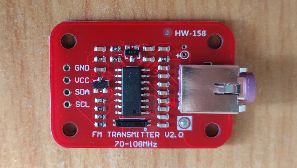
KT0803L (FM transmitter module)
16x2 Liquid Crystal Display (LCD)
Push Button
Bread board
Micro-B USB Cable
Jumper Wires (male to male)
Telescopic Antenna
3.5mm Audio cable
Software Requirements
Thonny IDE (python IDE for beginners).
MicroPython firmware for Raspberry Pi Pio.
Tools Requirements
Soldering Iron
Soldering wire
Soldering Flux
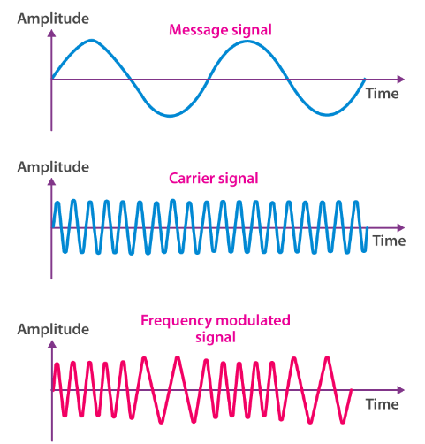
Frequency Modulation (FM) Frequency modulation was Invented by 'Edwin Howard Armstrong' in 1933. In frequency modulation the frequency of a high frequency carrier wave is varied (changed) in accordance with the instantaneous value of modulating signal (message signal). In frequency modulation the amplitude of the high frequency carrier wave remains constant. In frequency modulation there is low distortion in comparison to Amplitude Modulation (AM), so this is why FM is preferred more over AM for transmitting audio. In ancient time the frequency modulation is used only for radio broadcasting and receiving but In present time FM (Frequency modulation) is being used for transmitting high quality audio signal. In frequency modulation we can transmit mono or stereo audio signal. Waveforms of frequency modulation are given below:
Raspberry Pi Pico I am using the Raspberry Pi Pico microcontroller development board as the brain of this project. Raspberry Pi Pico, RP2040 features a dual-core Arm Cortex-M0+ processor with 264kB internal RAM and support for up to 16MB of off-chip flash. A wide range of flexible I/O options includes I2C, SPI, and - uniquely - Programmable I/O (PIO). Raspberry Pi Pico can be programmed using C/C++, MicroPython or Circuit Python programming languages. I am expert in MicroPython so I am using the MicroPython programming language for programming the Raspberry Pi Pico microcontroller. For more information about programming the raspberry pi pico using MicroPython, please visit the following link: https://www.instructables.com/Raspberry-Pi-Pico/
KT0803L (Monolithic Stereo Fm Transmitter Chip) KT0803L is a monolithic digital FM transmitter. It is designed to process high-fidelity stereo audio signal and transmit modulated FM signal over short range. It is based on the architecture of KT0801 and it is also an upgrade version of KT0803K and KT0803M. The additional features added to KT0803L are standby mode through software, ALC (Automatic Level Control), multiple reference clock, Increased SNR performance and frequency response. The KT0803L features dual 20-bit delta-sigma audio ADCs, a high fidelity digital stereo audio processor and a fully integrated radio frequency (RF) transmitter. An on-chip low-drop-out regulator(LDO) allows the chip to be integrated in a wide range of low-voltage battery-operated system with power supply ranging from 1.6V to 3.6V KT0803L is configured as an I2C slave and programmed through the industry standard 2-wire microcontroller interface. It is available in a generic 16-pin SOP package. Here I am using KT0803L IC based FM transmitter module for simplicity.
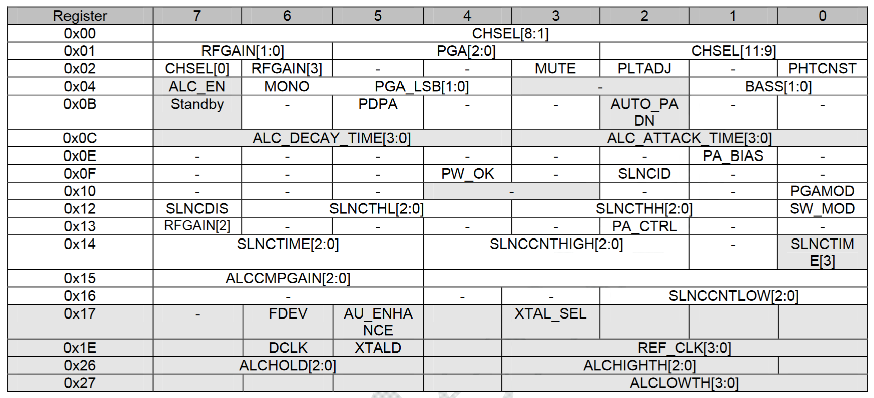
Register Bank of KT0803L KT0803L has eighteen 8-bit registers, the group of all eighteen registers is called register bank. The register bank stores channel frequency codes, calibration parameter, operation status, mode and power controls, which can be accessed by the internal digital controller, state machines and external microcontrollers through the I2C serial interface. All the registers are 8-bits wide.
Discuss about 18 registers is not possible here, so I am going to explain the first four registers (which are responsible for transmission frequency, channel selection, audio channel and power selection etc. For other registers you can carefully read the datasheet of KT0803L.
Register-1 Address of register-1 is 0x00 (in hexadecimal format) and its default value (data) is 0x5C (in hexadecimal format). It is an 8-bit register. All 8-bits are as following: CHSEL8 (MSB) CHSEL7 CHSEL7 CHSEL5 CHSEL4 CHSEL3 CHSEL2 CHSEL1(LSB) value(0 or 1) of all the bits of this register is decided by the channel value (in binary format).
Register-2 Address of register-2 is 0x01(in hexadecimal format) and default value (data) is 0xC3 (in hexadecimal format). It is an 8-bit register. All 8-bits are as following: RFGAIN1(MSB) RFGAIN0 PGA2 PGA1 PGA0 CHSEL11 CHSEL10 CHSEL9 (LSB) value (0 or 1) of all the bits of this register is decided by channel value (in binary), Power gain and Transmission power.
Register3 Address of register-3 is 0x02 (in hexadecimal format) and default value (data) is 0x40 (in hexadecimal format). It is an 8-bit register. All 8-bits are as following: CHSEL0 (MSB) RFGAIN3 Reserved Reserved MUTE PLTADJ Reserved PHTCNST(LSB) Value (0 or 1) of all the bits of this register depends on channel value (in binary), RF gain, Audio mute, Pilot tone amplitude and pre-emphasis time constant.
Register4 Address of register-4 is 0x04 (in hexadecimal format) and default value (data) is 0x04 (in hexadecimal format). It is an 8-bit register. All 8-bits are as following: ALC_EN (MSB) MONO PGA_LSB1 PGA_LSB0 Reserved Reserved BASS1 BASS0 (LSB) Value (0 or 1) of all the bits of this register depends on ALC (Automatic Level Control) enable, Power gain, audio cannel and bass boost control.
Calculate The Channel Value Default transmission frequency of KT0803L is 86MHz instead of 89.7MHz in KT0803K and KT0803M. Channel value is calculated using FM broadcast frequency (MHz) by the following formula. channel value = [Broadcast Frequency(MHz) x 20] calculated channel value is in decimal format but we need value in binary format so we convert the decimal value into binary with the following formula. channel Value(in binary) = DectoBin[channel value(in decimal)] for an example, for broadcast frequency of 87.0MHz the channel value is 1740 (in decimal) and 011011001100 (in binary). For this channel value the values of CHSEL[11:0] bits will be as given below. Bit Value CHSEL11-------------> 0 CHSEL10 ------------> 1 CHSEL9 --------------> 1 CHSEL8 --------------> 0 CHSEL7 --------------> 1 CHSEL6 --------------> 1 CHSEL5 --------------> 0 CHSEL4 --------------> 0 CHSEL3 --------------> 1 CHSEL2 --------------> 1 CHSEL1 --------------> 0 CHSEL0 --------------> 0
Calculate the Data of the Resisters Here I am calculating the values for registers-1, 2, 3 and 4 to broadcast my stereo audio signal at 87.0 MHz FM frequency. For this frequency the channel value is calculated as following. channel value = (87.0 x 20). channel value = 1740 (in decimal). convert the decimal number 1740 into its binary equivalent and we get a binary value of 011011001100. Now we put these bits into the Register-1, 2 and 3 as given below: CHSEL11-------------> 0 CHSEL10 ------------> 1 CHSEL9 --------------> 1 CHSEL8 --------------> 0 CHSEL7 --------------> 1 CHSEL6 --------------> 1 CHSEL5 --------------> 0 CHSEL4 --------------> 0 CHSEL3 --------------> 1 CHSEL2 --------------> 1 CHSEL1 --------------> 0 CHSEL0 --------------> 0 The 8-bit data that we have to store in register-1 is 0x66 (in Hexadecimal).
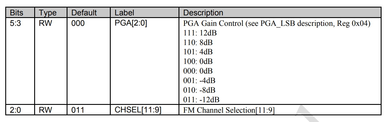
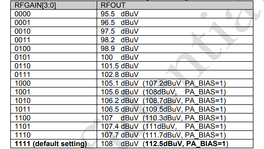
I am keeping the power gain 4 dB for this the values of PGA2, PGA1 and PGA0 bits of register-2 are 101 respectively. The different values of these bits and corresponding power gains are tabulated in the given table: I am keeping the Transmission power 100dBuV for this the values of the RFGAIN3, RFGAIN2, RFGAIN1 and RFGAIN0 bits will be 0101 respectively. We can easily get the values of these bits with the help of table given below: Now the register-2 will have the following value. RFGAIN1 ----------> 0 RFGAIN0 ----------> 1 PGA2 ----------> 1 PGA1 ----------> 0 PGA0 ----------> 1 CHSEL11 ----------> 0 CHSEL10 ----------> 1 CHSEL9 ----------> 1 The 8-bit data that we have to store in register-4 is 0x6B (in Hexadecimal).
I am not using the automatic level control so i reset the ALC_EN bit, I am keeping the audio stereo so I reset the MONO bit. If MUTE bit is 0 the mute is disabled and if 1 then mute is enabled. I am keeping it 0 to disable the audio mute. I am keeping the PLTADJ (pilot tone amplitude adjustment) bit to 0 for low amplitude. I am using the pre-emphasis time constant of 50usec. so I set the PLTADJ bit. CHSEL0 ---------> 0 RFGAIN3 ---------> 0 Reserved ---------> 0 Reserved ---------> 0 MUTE ---------> 0 PLTADJ ---------> 0 Reserved ---------> 0 PHTCNST ---------> 1 The 8-bit data that we have to store in register-3 is 0x01 (in Hexadecimal).
I am not using the automatic level control so I reset the ALC_EN bit. I am using the stereo audio so I reset the MONO bit. I am not using the bass boost control so I reset the BASS1 and BASS0 bits. The values of PGA_LSB1 and PGA_LSB0 bits are 11 respectively for gain of 4dB. ALC_EN -------> 0 MONO -------> 0 PGA_LSB1 -------> 1 PGA_LSB0 -------> 1 Reserved -------> 0 Reserved -------> 1 BASS1 -------> 0 BASS0 -------> 0 The 8-bit data that we have to store in register-4 is 0x34 (in Hexadecimal)
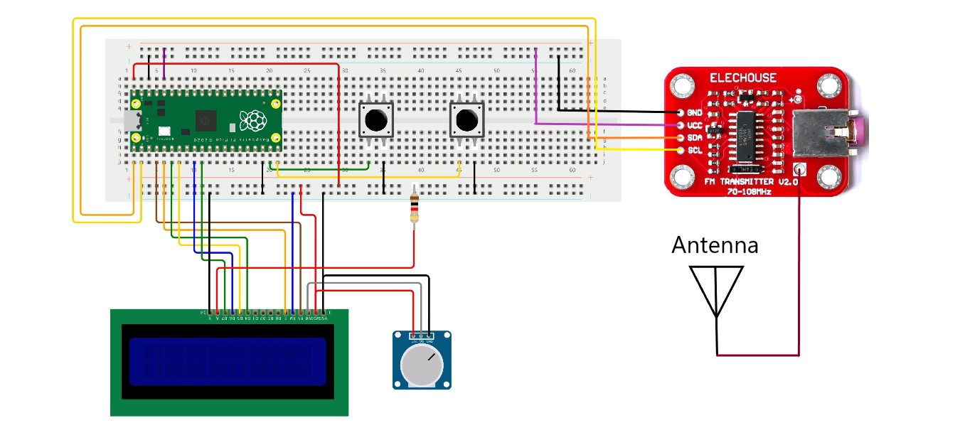
Schematic Diagram For making the proper connections you can take the help of given schematic diagram.
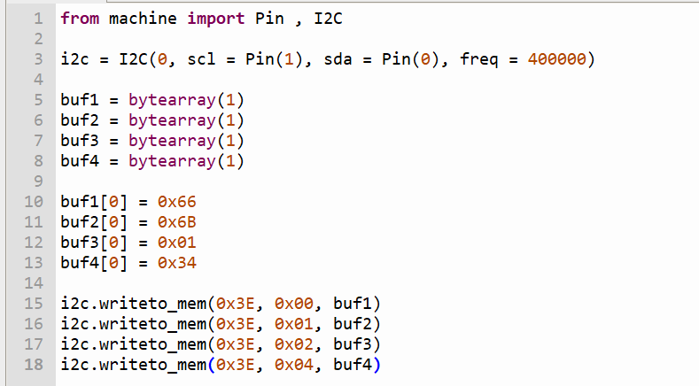
Example code for Testing KT0803L Module I wrote a simple micropython program to change the default values of Register-1, 2, 3 and 4. I am storing my calculated data ( 0x66, 0x6B, 0x01 and 0x34) in registers-1, 2, 3 and 4 respectively. Write the following lines of micropython sketch in your editor and run it on your pico after making all wiring connections as showed in schematic diagram.
MainMicropython Program Copy the following MicroPython sketch into your Thonny editor and save it in the Raspberry Pi Pico directory with name as main.py. It is necessary to keep the file name as main.py.
from machine import Pin, I2C from gpio_lcd import GpioLcd from time import sleep
Create a function 'setChannel' for calculating the channel value and calculating the data for each register. creating a bytearray for storing the calculated data to register-1, 2, 3 and 4. After storing the calculated value of all the four registers it sends these data bytes to KT0803L for storing in registers.
Create a while loop that runs continuously and determines the reading of the states of button1 and button2 for increasing or decreasing the transmission frequency.
while True: if(button1.value() == 0 and frequency > 87.0): sleep(0.15) frequency = frequency - 0.1 setFrequency(frequency) if(frequency < 100.0): lcd.move_to(3, 1) lcd.putstr(str(round(frequency, 2))) if((frequency - 100.0) >= -tolerance): lcd.move_to(3, 1) lcd.putstr(str(round(frequency, 2))) if(button2.value() == 0 and frequency < 108.0): sleep(0.15) frequency = frequency + 0.1 setFrequency(frequency) if(frequency < 100.0): lcd.move_to(3, 1) lcd.putstr(str(round(frequency, 2)))


Discussion (3 comments)
samsvl 7 months ago
EN0094479ID 7 months ago
Brian Tristam Williams 7 months ago
F4HUY 7 months ago
TheEditor 7 months ago