

Raspberry Pi Doorbell bodyguard [150400]
Do you want to know who ring at your door but you are too far from your home? This system works with a Raspberry Pi and a GSM-BoB module. If someone rings at your door, the Raspberry Pi will take a picture and send you by MMS the photo.
Do you want to know who rings at your door but you are too far from your home?
This system works with a Raspberry Pi and a GSM-BoB module. If someone rings at your door, the Raspberry Pi will take a picture and sends you the photo by MMS. Once you have the picture, you can decide to call the module to speak with the person or not. Watch the video here.
This system works with a Raspberry Pi and a GSM-BoB module. If someone rings at your door, the Raspberry Pi will take a picture and sends you the photo by MMS. Once you have the picture, you can decide to call the module to speak with the person or not. Watch the video here.
Here are the different steps to configure your Raspberry Pi:
1) You have to download an OS (Operating System). Personally I used Raspbian but you can take another one if you prefer (https://www.raspberrypi.org/downloads/)
2) Use a software to put the OS in the SDcard (like Win32DiskImager)
3) Once the OS installed, you must do some configuration to allow the camera and the UART.
4) Open a terminal and write: “sudo raspi-config” -> There is a line marked “Enable the camera”. You must reboot afterwards.
5) You can now take picture with the command: “raspistill –w 1280 –h 1024 –o image1.jpg”. You can also write: “help raspistill”
to see all available commands.
to see all available commands.
6) For the UART, you have to modify a file to tell to the Raspberry that you want to use the UART:
- Go to the file “cmdline.txt” in the folder “/boot/”
- In the document you will see something like:
dwc_otg.lpm_enable=0console=ttyAMA0,115200 kgdboc=ttyAMA0,115200console=tty1 root=/dev/mmcblk0p2 rootfstype=ext4 elevator=deadline rootwait You have to remove this part
console=ttyAMA0,115200 kgdboc=ttyAMA0,115200(to remove the use to the UART at the lunching of the Raspberry- In another file, you have to put a line in comments (or delete). It is in the file “/etc/inittab”. You will see:
T0:23:respawn:/sbin/getty -L ttyAMA0 115200 vt100
You have to put the line in comments so put:
#T0:23:respawn:/sbin/getty -L ttyAMA0 115200 vt100
7) You can now restart the RaspberryPi
Discussion (6 comments)
Lucky 8 years ago
BUT....
Our script didn't work anymore, it just raised the exception that the serial port was already open. First we thought there was still 'something' in the operating system that kept the UART occupied, but we couldn't find anything. Eventually we found out that with Jessie the Python script line already opened the serial port, causing the following line to raise the aformentioned exception.
The solution is easy of course (just delete the second line), but it took quite some time before we discovered what was wrong....
Lucky 9 years ago
Lucky 9 years ago
Copper layout V2.1 (49kb)
PCB overlay V2.1 (70kb)
Lucky 9 years ago
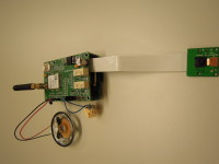
Finally built the prototype and finished the Python Script for our hi-end doorbell!
How it works
It is rather easy to use: when a visitor rings your doorbell, the Raspberry Pi (RPi) Cam takes a picture of him/her and sends this photo to your cell phone in an MMS message. This message also has a short text containing the doorbell’s phone number which acts as a hyperlink on your cell phone. You can tap this link and start a phone conversation with the visitor via the microphone and speaker of your doorbell, which are mounted as a kind of intercom at your front door. The cell phone module is set to auto answer so it will go off hook after the first two ring tones, and will hang up as soon as you terminate the call on your cell phone. If you recognise the person in the picture you can also skip the phone call and send a text message that contains a password to the module to open the door for your visitor, or you can decide to send this ‘open sesame’ after the conversation. Of course you’ll need extra hardware to make this happen, the module just switches a small relay that can control or trigger a (commercially available) door opener.
First of all: rates for sending an MMS can differ considerably between providers, do some ‘shopping’ before you buy a SIM card for this application. MMS is not very popular, and exact charges for this service can be hard to find (i.e. buried deep in the provider’s conditions). We were not very happy with the last SIM card we bought for experimenting, we spent 35 Euro cent for every message sent.
Door opener and why I wouldn’t use this feature myself…..
I am not in favor of remote door openers, but I added this feature to the project because other people thought it would be handy. My biggest concern is that burglars will always find a way to hack the hardware. It's very important to install the Raspberry Pi our board plus the wiring in an burglar-proof case or safe place to prevent this. Remember that every chain is as strong as its weakest link, so we will NOT take any responsibility for people entering your house by hacking the system.
The Python script checks both the password and the phone number of the cell phone that sends the text message, which is a fairly secure –but not watertight- solution. Even if someone knows the password, he’ll still need your phone to open the door. Personally I would only use this doorbell to have some way to communicate with a visitor and ask to wait until I’m home or to come back later, in some cases to tell them to get lost anyway ;-) The picture can be helpful to decide if it’s really necessary to speak to the visitor. I would use a remote door opener only when I am at home and unable or just too lazy to open the door myself, but that is my choice of course.
Schematic and PCB
The main purpose of this design was our doorbell project, but it can also be used as M95 breakout board for other applications, that’s why we also added K1..K4 to the board to give access to all I/Os of this GSM module. The board has the same shape and size as a Raspberry Pi, K5 mates with a section of the RPi’s expansion connector and connects power supply, UART and three digital I/Os to our board.
If you want to use the board for your own application and want to use the UART in handshake mode, please remove zero Ohm (jumper) resistor R14.
Most of the circuit is copied from the Quectel M95 Hardware Design Manual. The 4.4V power supply, the audio part (speaker and microphone) and SIM card hardware are rather straight forward. In an earlier contribution I already explained why we don’t use 3.3V supply for the M95, it would have made interfacing with the RPi a bit easier. Ah well, it would have saved voltage divider R6/R7 on the TxD connection, that’s about it, but 4.4V is not really a well-known voltage level in digital systems. Remember that the RPi’s I/Os are all 3.3V and it’s easily damaged when this level is exceeded.
The RPi sends AT-commands to the M95 via the UART and (in some cases) reads responses of this GSM modem. In our application the RPi always initiates the communication. The M95 can send unsolicited result codes (URCs) to the Rpi, for example when a text message arrives or in case of an incoming phone call, but these codes are not handled by our script. To minimize latency between pushing the doorbell button and reception of the MMS, the UART uses the highest possible baudrate for the M95, i.e. 115200 baud.
RE1 is controlled directly by the doorbell button and can be used to trigger an existing normal bell system inside your house. Jumper JP1(which can also be connected to an ON/OFF switch) can be used to interrupt the trigger signal for the RPi in situations where you don’t need the MMS functionality of the doorbell, in that case only RE1is switched when there’s a visitor at your front door.
RE2 is switched by a digital output of the Rpi and can be used to trigger the optional door opener.
The 33pF capacitors are applied for filtering out 900MHz RF interference when the M95 is transmitting, the 10pF ones for 1800MHz.
The PWRKEY input of the M95 is a signal that toggles this modem between standby and on. After power on this signal must be triggered to put the modem in operational mode.
The Python doorbell script
Before you can run the script on your doorbell system, there are some constants to be defined in the source code. It needs to know the number of your cell phone (i.e. recipient of the MMS, in the script defined as ThatNumber), the number of the SIM card for the M95 module (used to send a hyperlink in the MMS text, defined as ThisNumber) and provider specific MMS settings. Consult the website of your provider (i.e. the provider of the M95’s SIM card) to find the right MMS settings for:
You can define these constants as APN, MMSC, MMSproxy and MMSport in the script. In the
Another thing is the password for the optional door opener, defined as VerySecret in the source code.
Running the script
That’s all you need to know about the script to get it up and running on your doorbell, the rest of this contribution will give some more details for people who want to know how the programming is done and/or want to change the original script for their own application. One thing though: since the script redefines the RPi’s I/O pin settings, it will only run if the user has super user rights. To accomplish this, open a command line with TXterminal and start with:
sudo su
<set directory to the folder containing the script>
python MMSautoSend.py
This procedure can be used during testing of the script, when all the modifications are done it’s more appropriate to have the RPi automatically start the script on power up or reset, the system then can be started and implemented without using and connecting a mouse, keyboard and display to the RPi.
There are many ways to auto-start a Python script on an RPi, we took the quick (and dirty?) way of adding it to the RPi’s crontab. In TXterminal, type:
crontab –e
In the editor that is opened then, add the following line:
@reboot python /home/pi/ScriptsPython/Files/MMSautoSend.py
Where the path /home/pi/ScriptsPython/Files/ must be adapted to the path where you stored the Python script. Note that you don’t need to explicitely claim super user rights for scripts added to the crontab.
Save the file, restart your RPi and it will automatically run the script at every reboot.
More adjustments to the script
There can be some tweaking done on the performance of the system, like the size of the picture. This is a trade-off between the quality of the photo and file size. Of course the most important thing is to be able to recognize the person at your front door. A picture of 160 x 120 pixels (defined in the script as camWIDTH and camHEIGHT) proved to be working good here, resulting in files of 40~50kB sent via MMS. Please note that higher resolution pictures do not only influence transmission time, but some providers charge extra if the picture file is bigger than a certain number of bytes.
There’s also a parameter to adjust the brightness of the camera (camera.brightness = 60 in the script) that may need adjustment depending on the location where the camera is installed, same goes for camera.vflip and camera.hflip if the orientation of the picture needs to be changed.
The speaker volume level and microphone gain can be adjusted by changing SpeakerLevel and MicGain in the script.
Details on the script and AT-commands used
The script starts with import of the libraries used, followed by the definition of the I/O pins, constants like the phone numbers and MMS settings.
One important thing is that the M95 needs some time to process the AT-commands it receives, most of these lines are followed by a time.sleep() call.
The power-up sequence could be omitted in this script, apparently the PWRKEY line is already triggered correctly when the RPi is completely booted. However, since this behavior is rather unpredictable the first AT-command sent is a Power Down, the only way to ensure that the module is in stand-by mode when the PWRKEY is pulsed to switch the M95 on. If it is already in standby when this AT-command is sent, the M95 will simply be able to receive it because its UART is switched of.
Three subsequent ATs are needed to auto-set the baudrate of 115200.
The M95 has two possible connections for a speaker/microphone pair, default are the non-amplified MIC1 and SPK1, AT+QUAUDCH=2 selects the amplified pair where our speaker and microphone are connected.
Our SIM-card was not protected with a PIN, there are two lines (AT+CPIN and a sleep) that must be uncommented in the script if your SIM is PIN protected. You must change the corresponding PIN code in the script (default PIN is assumed to be 0000).
There are more locations possible for storing received text (SMS) messages, we selected storage in the SIM card.
Next the number of ring tones before the M95 goes off hook is selected. One would be enough in this application, but setting it to two (ATS0=2) will sound the ring tone once in the speaker, as a sign for the visitor that there is some activity.
Then main loop of the script is entered, which always starts with checking if there is an unread SMS stored on the SIM card. If there is the originating phone number is compared with our trusted number defined in ThatNumber, if they match and the text message contains the right password, then the door opener output is toggled, RE2 will close during one second. You can adjust this interval to the time you need for your door opener hardware.
Only the first storage location for SMS on the SIM card is checked for a correct ‘open’ message, it’s rather unlikely that more messages are received during one loop of the script, all locations are cleared once this message is processed.
Next the doorbell button is checked, if it is not pressed the main loop starts again. If it is pressed the picture is taken, the MMS composed and sent to your cell phone. And then it’s up to you decide what to do: either start a phone conversation with your visitor, open the door or just ignore the visitor. After all, there’s nobody home…
Python script for MMS doorbell (2kb)
150400-schematic-v11.jpg (188kb)
150400 Compositions in colour for DTP v1.1.pdf (64kb)
Lucky 9 years ago
Script
Dorian wrote the framework of a Python script sending an MMS with a JPG file stored on the RPi and it basically worked, some adjustments and additions were needed to get it right.
The most tricky part is sending the JPG file that contains the picture of the person at your front door. Except for sending the new file, there are two things that need to be done. First we must make room in the RAM of the M95 and/or remove the previous file. If we try to write a file with the same name twice, the transmission of the picture between the RPi and the M95 will fail. The AT-command 'AT+QFDEL='RAM:*' clears all files in the M95's RAM, preparing the module to receive the new picture.
Second, before sending the JPG we must know the size of this file, i.e. let the M95 know how many bytes will be transmitted. Since JPG is a compressed file format, the file size will vary depending on the picture's content rather than the size of the original picture taken. The Python library OS contains a function 'getsize' to do this calculation for us, so that's not such a big issue either.
Debugging
While debugging a script that communicates with the M95 it's very useful to 'listen' to the messages on the UART, especially the responses of this module to the commands sent by the RPi. First I thought the extra debugging UART of the M95 could be handy, but apparently it continuously sends non-ASCII information on this interface. If you view these data in a terminal program, you must look carefully to spot the legible parts of AT commands and responses, but it proved to be of no use to debug the Python script. Since there's hardly any information on this debug UART in the documentation of Quectel, I decided not to spend any more time to figure out how it works. I just tapped the information sent by the M95 by connecting the RXD of an FTDI cable to the TXD of the M95, and viewing its output on my PC with a terminal program. Of course I could also have used the script on the RPi to view/evaluate acknownledge and error messages, but this was a relatively easy way to see what was going on.
Camera
And then of course we have to instruct the RPi to take a picture, but with the Python 'picamera' library this is an easy job. A simple 'camera.capture' command saves a JPG copy of the picture taken, preparing it to be sent to our GSM module. However, there are some parameters that must be adjusted, like the orientation, number of pixels and brightness. The brightness may need adjustment at a later stage, depending on the environment where the camera is placed.
The size of the photo (although not not directly proportionally related to the JPG's file size) is very important: the bigger the file, the longer the transmission from the RPI to the M95 and from the M95 to your cell phone will take. There's also a 300k limit to the size of a file attached to an MMS message, although bigger files may be sent at extra charge. Here we are facing a trade off between picture quality and -most important!- transmission time: if it takes too long to receive the MMS plus picture, chances are that our visitor has already left before we can contact him (or her), making this whole project useless. Fortunately we don't need high resolution pictures, as long as we can recognise the person at the front door. With the settings in the current script it takes about 45 seconds to receive the MMS, which appears to be acceptable, unless you have very impatient visitors who leave immediately if you do not answer, but chances are that you didn't want to see those people anyway ;-). There is some unpredictable latency in the path from the M95 to the reception of the MMS on your cell phone, which mainly depends on your mobile provider and the network available.
Talk to the visitor
The 'call back function' is really simple to implement, the M95's phone number is contained in the MMS as a hyperlink, just dial this number and the M95 will automatically answer after a preset number of rings (set by 'ATS0=x'). The microphone and speaker connected to the MIC2 and LOUDSPK pins of the M95 make it possible to have a phone conversation with the visitor, the M95 will automatically hang up when the carrier signal is lost, i.e. after you end the call on your cell phone. Note that the audio channel on the M95 has to be switched with 'AT+QAUDCH=2' to use these amplified analog I/Os, default are the non-amplified MIC1x and SPK1x. The gain of the microphone and speaker amplifiers can be set by using 'AT+CLVL'.
The script still needs some finetuning, but the concept works fine, absolutely good enough to make a complete project of it. But since in most situations the hardware has to be mounted outdoors, we have to design some dedicated hardware, preferrably a shield for the RPi and fit it into a some water and vandal proof case. The GSM BOB we presented earlier will not be used, it's not possible to make a nice compact design with it in this application.
Extra hardware and software needed
1. Of course a doorbell button is needed, the script like is is now just starts, takes a picture and sends the MMS, no digital input for a switch implemented yet.
2. Apart from sending an MMS, there must be some connection to an existing doorbell system. Unfortunately there's no such thing as a 'standard bell', there are AC and DC types, ranging from low current electronic sounders to (old fashioned) high current electromechanical bells. We added a miniature relay to our design to keep this 'interface' as universal as possible. It can switch 500mA, which will be enough in most cases, but depending on your doorbell you may need some extra hardware (e.g. a higher current relay) to control it.
3. One MMS per visitor is enough, there must be some delay implemented in the script to prevent multiple messages being sent. (e.g. the postman always rings twice)
4. There also must be some way to switch the camera and MMS functionality off, leaving just a normal doorbell installation. Both sending and receiving an MMS will cost some money, depending on your mobile phone provider and you don't need this feature when you're at home. We added a physical connecting for such an on/off switch, but we may add a feature to switch the MMS remotely by sending an SMS.
Lucky 9 years ago
Lucky 9 years ago
ClemensValens 9 years ago
Lucky 9 years ago
As you may know the RPi works on a VDD of 3.3V, whereas the BOB uses a VDD of 4.4V. To avoid the need for level shifting to connect these two boards, I decided to lower the internal supply voltage of the BOB to 3.3V, after all that's just a matter of changing the voltage divider of MIC29302 voltage regulator.
I shouldn't have bothered.... Quectel specifies the supply voltage of the M95 GSM module between 3.3V and 4.6V, but the module keeps sending an Unsolicited Result Code (URC) 'UNDER_VOLTAGE WARNING' every 5 seconds if it's lower than 3.5V. Although this is mentioned in the datasheet, I don't really understand why this is implemented. After all the datasheet suggests that the module will work normally at 3.3V, but these URCs are sent via the UART, interfering with the serial communication between the RPi and M95. All in all I don't see any logic in logical high levels in a range of 3.5V to 4.4V, but we have to live with it if we want to use the M95.
But still, since the only real voltage issue is with the TxD from the M95 to the RxD or the RPi a simple resistor divider will do, let's just keep the original 4.4V on the BOB to keep the UART communication clean.
Lucky 9 years ago
There are two things I'm not completely certain of.
First I must admit that I only once received an MMS, isn't this standard already kind of obsolete?
Furthermore, will the complete system be fast enough to have practical use? If it takes too long to receive the MMS and react to the fact that there's someone at your front door, it's rather likely that the visitor already leaves before you can contact him/her. There's one way to find out: let's test it!