

Remake Elektor weather station
Lab Team Note: This project no longer supported, but comments are always welcome. New improved version of the ESP32 Weather Station [180468] We keep the ESP32 and added the wishes and request we got for the old one
[Firmware]
- User contributed firmware for ESPHome by hugokernel can be found here: https://github.com/hugokernel/esphome-weather-stationThe current firmware presented in this article does not receive any other main updates at the moment. We try to do some maintenance, but we recommend to use the user contributed replacement firmware for ESPHome from hugokernel for the station.
This a remake of the Weather Station published in the January 2019 issue of ElektorLabs. There were some issues with this project -both in hardware and software- that needed to be tackled. Also we got request of adding a few functions to the station that can't be done with the current PCB anymore without heavy soldering. That's why we decided to revise the hardware completely, keep the sensors (and add some more sensors) and rewrite the firmware to make improve the functionality of the weather station. The housing is now more complact and wireing may be take a bit longer. But in the end results can be really nice looking
[Parts]
- The display used is a HD44780 2x16 character LCD with an I²C backpack you can find for various Arduinboards running at 5 volts e.g on the Elektor StoreDisplay (2*16) https://www.elektor.de/2x16-character-lcd-blue-white-120061-77
I²C Backpack https://www.elektor.de/iic-i2c-serial-interface-adapter-module
- The µSD-Card socket used is a third party product that can be order from the Elektor Store (https://www.elektor.de/minisd-card-module)
We know that the BOM is not easy to be sourced within the Elektor shop. If you have any questions please leave a comment.
[Current Projectstate]
- Currently this project is in Maintanancemode. Not big updates or heavy improvements are currenlty planned.[Update 3.12.2019]
We have the set of feature ready for now. The PCB in the cylindric part of the plastic ( the barometer one ) will not be used and replaced with our own PCB. For more comfort you can still use the connectors as they will also be there and just move from there to the ESP32. This new PCB also now houses a proper place for the BME280 from the Elektor Shop, so no longer big amounts of hot glue are required to place it. Also we plan to add a second sensor connector for a pure pressure and temperature sensor. All connections to the sensors are made with I²C, besides the plastic parts for the windspeed , direction and rain amount. We will keep the signals and connect them directly to the ESP32.
This will result in 7 wires required here, VCC ( we used 5V and a LDO to get 3.3V ) , GND, RAIN, WINDSPEED, WINDDIR, SDA and SCL. This means you can use cheap 8 wire cables like those found in ethet ones to connect the station to the ESP32.
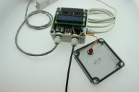
For the ESP32 we changed the enclosure. With the last one it was a bit tricky to get the cables waterproof to the inner. We now have a enclosure with predefined breakout points for the cables and a transparent cover, so you can see inside the station. And here come a few changes.
The last station had a kind of charging circuitry for solar panels and lead battery cells. As solar charger are now not that expensive any more and will do a much better job that the simple components used in the old station, we removed this completely. Instead we setup a proper under voltage lockout, so that your batteries won't get deeply discharged over time.
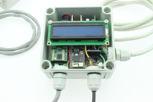
The power input will still be 7 to 12 Volt and using a DC / DC converter build up from THT parts. What is added is a little I2C LCD ( 2x16 Character ) as option and also some buttons for navigation. We added a sd-card slot, so you can write the data to a sd-card for later use or storage.
Something else? Yes, we reserved a bit of space for a LoRa-Module ( RFM95 ), so you can send Data also using LoRa or even LoRaWan. This means the station can gain a bigger range than with the WiFi alone.
Last but not least you can connect a particle sensor to the station. This can be a SDS011 or a HPMA115S0-XXX. We may add more sensors later, but for now that shall be enough in the beginning.
Software will be changed to accommodate for the new hardware attached to it, but all drivers that were inside the old station will be included into the new one. As we have a spare Pin left in the Cable and some spare pins on the ESP32 we can also consider adding a DS18B20 pin to the station.
The main problem of the ESP32 Pico Kit board still is power consumption, as these will be at 100mA average at 5V input. This is due to the ESP32 and the WiFi and 25mA will be drawn useless from the USB-Serial converter on the board, as the shutdown pins are not connected, nor they can be controlled form the ESP32 without soldering.
To get power consumption less worse we will add a start / stop mechanism to the WiFi that it is only activated if the station needs to send data. This will also mean that, if this mode is activated the usual config via WiFi won't work any longer.
So as you can see we have some work to do now, to make the new station ready in time for the spring season. The good thing is that those who already have a station can mostly swap the PCB as we keep the Pico Kit as its main MCU.
[Update 9.12.2019]
The basic bits for the rain and wind sensor are done and the PCB is on its way. The next thing will be the WiFi, as we will add the start - stop mode and the data upload. Also the LMIC has been implemented to allow LoRa communication, but the LMIC and the ESP32 are not really friends, as the RTOS sometimes causes a bit of a hassle.
[Update 11.12.2019]
So far drivers for the HPM115S0 and SDS011 are implemented and working. For the SDS011, the last one we had in the lab sadly has a mail function, as the fan is not working or we send actually the command for self destruct. The HPM115S0 form Honeywell is working and an abstraction lays let the software switch for both parts without heavy code changes. This also means we can support more particle sensors in the future.
For the I²C Bus we have now basic support for:
- BME280 ( 0x77 / 0x76 )
- Wuerth WSEN-PAD ( 0x5C / 0x5D )
- Veml6070 ( 0x38 )
- TSL2561 ( 0x29 / 0x39 / 0x49 )
- VEML6075 (0x10)
- TSL2591 ( 0x29 )
Next thing will be the wifi and the start stop mode. Also on tge todo list is 1-Wire for DS18B20 sensors.
[Update 19-12-2019]
Hardware
This project is split up into three PCBs: the main board 191148-1 that will be installed in a waterproof case outside, but close to your house and the connector board 191148-2 that fits into the case of the thermo-hygro sensor and replaces its internal hardware. It also provides RJ11 sockets for connecting the wind and rain sensor modules of our weather station. The boards are interconnected with a 7-wire cable, an 8-wire ethernet cable will do fine.
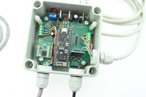
The first board contains the power supply and its protection circuitry (T1, IC1 and MOD1), an ESP32 Picokit module (MOD2), a micro SD card connector for data logging (K5), a 2 x 16 character LCD with I2C interface (K6), an optional RFM95 break out board for LoRa connectivity (MOD3, not supported yet!), connections to the second board (K2, K3, K4) and to a Honeywell particle (dust) sensor (K7 and K8). The latter may easily be damaged by frost and therefore we didn’t connect it to the thermo-hygro sensor case, which must be installed in more open space, not too close to the house.
The third PCB (191148-3) is more like an adapter for mounting and connecting the Honeywell HPMA115 dust sensor, so it can easily be fixed in the same type of case as the weather station’s main PCB.
Main board 191148-1
The weather station is (normally) powered by a 12V rechargeable battery, which is charged by a solar panel and an external solar charger.
T1 and R3 serve as polarity protection, the MOSFET will only conduct if the battery terminals are connected the right way.
If -for whatever reason- the charging process doesn’t produce enough energy to compensate for the power dissipated by the weather station, this battery must be disconnected to prevent deep discharge and damage. For this task we selected a good old programmable voltage detector ICL8212, or rather its CMOS successor MAX8212 from Maxim Integrated. With only three external resistors for adjusting thresholds/hysteresis and an external p-channel MOSFET as switch it does exactly what we want: deep discharge protection for the battery.
With the current values for R2, R8 and R4 we have an undervoltage lockout, that switches off the battery when its voltage drops below 10.5V and switches it on again when it rises above 11.1V.
Power supply
A DC/DC converter (MOD1) steps the 12V battery voltage down to the 5V supply voltage for this project, LED1 is the power on indicator. The ESP32 Picokit module has an internal 3.3V regulator, its output is routed to pins 18 and 21 of this module and these pins supply the 3.3V needed for the circuit on the main board.
ESP32 Pico Kit module
This is of course the ‘brains’ of our weather station. It controls and reads out the sensors, displays information on the LCD, logs data on the SD card and communicates with an (indoors) computer via WiFi (or Lora, when implemented). It also contains a reset and a user button, plus a USB connection for flashing the weather station’s firmware.
I2C bus
This bus is used for communication with the LCD and air pressure/temperature/humidity sensors, but of course it can also accommodate other I2C compatible sensors or devices you may want to add to the weather station. In ‘normal’ operation jumpers JP1 and JP2 must be closed to provide the pull up resistors (R5 and R6) that are needed for this bus. If you connect an I2C device that already contains pull ups on the bus connections, you may either omit R5 and R6 or open the jumpers.
The LCD module also uses the I2C bus, with jumper JP3 you can select the appropriate supply voltage for this module, depending on the brand/model of the LCD, either 3.3V or 5V.
SD card
For the micro SD card connector we have chosen a small breakout board that is available in the Elektor shop, with a 100mil pitch pin header that can easily be soldered/connected to our main PCB. This BOB must be mounted perpendicular to the main board in order to access the card, you can either replace the straight pin header with an angled type or use pliers and some force to bend the pins 90 degrees. Be careful not to damage this small board, though!
Connector board 191148-2
Although this board also accommodates the pressure/humidity/temperature sensor (module), it mainly serves as connection between the ESP32 and the sensors of our weather station. It replaces the redundant board inside the thermo/hydro unit that is provided with the WH-SP-WS02 outdoor kit and fits perfectly inside its case.
The 3.3V LDO IC1 is the only active component on this PCB, apart from the three pull-up resistors R1 to R3 for the switches in the rain and wind sensors there are only connectors for the sensor modules used in the weather station.
The RJ-11 sockets connect to the wind (K4) and rain (K2) sensors, their positions correspond to the holes in and text on the case of the thermo/hydro unit.
Just like in the earlier version of our weather station, an Elektor BME280 breakout board can be used as temperature, relative humidity and air pressure sensor module at position MOD1 on the PCB. The numbering of the pins on this PCB matches the pin numbers on the breakout board. Alternatively, if you prefer to use a different brand of I2C environmental sensor module, you can connect it to MOD2 and omit the BME280 BoB at MOD1.
[Update 14.01.2020]
Software makes progress but some things may need to be finished later. Currently all the drivers we support with the old station are included and seem to work, also we have now for the particle sensors an autodetect feature in place that will decide if we have a SDS011 or HPMA115S0 attached to the serial port and automatically choose the appropriate driver. One thing that is interesting are the well-priced Chinese i²C LCD Backpacks, those run with 5V and could in theory opperate on a 3V3 I2C bus. As you get sometime more than you paid for we have here included pull-up resistors on the PCB that pull up to 5V, not that healthy for the ESP32, even if it works in the long run.
Also the Web interface got a "small" overhaul:

Still work in progress but getting closer to finish. Also, we will add the firmware from the former Weather station so that you can choose in the first place what you like more. And also, we are testing the new firmware for the older hardware.
[Update 19.03.2020]
Firmware now reached Version 1.1 and fixes a few bugs that were found. First the ArduinoOTA service will not work if the EPS32 is in AP mode, resulting in a Core panic and a restart loop. Also for the AP mode only the webserver will start, all other services like MQTT , openSenseMap will not be started as usually they can't connect to their servers. This will reduce CPU load while in AP mode. Somthing strage is the ESP32 webserver when running in AP mode. If you connect with a current Chrome, Internet Explorer or Vivaldi, those browser will have trouble louding multiple files from the webserver at once. Firefox currenty runs fine. This happens only in AP mode, if the station is running as WiFi Client the mentionend browsers work just fine.
This minimize the effect in AP mode, the website has been optimized to have all javascript and html in one file, this helps to get the station configured. Something else new is the way the firmware now handels updates. You can now upload a new binary via "Update Firmware" and also upload the webpages with "Update Webages". Both options requiere a binary file. While it is easy to generate the firmware itself, the webpages requiere a bit more work and will be discussed later. Also some minor tweeks are now in place to reduce the amount of serial messages generated by the station. Currently it is investigated if a small serial and telnet command interface can be integrated into the firmware.
Still on the wishlist is OneWire support. The station itself has been prepared for that and the connections on the PCB are already in place, "only" softwaresupport needs to be added, but it is on it's way. A bigger step will be the LoRa integration, as the ESP32 has for LoRa a horrible timing and if we use the LMIC this is a kind of awfull combination in the first place.
[Update 18.09.2020]
It has been a while, but we updated the firmware in the meantime have now reached version 1.5. May thanks to our readers and those who reported all the misshaps left in the code. The code is not perfect as many things, as with all projects, can be still imroved. For the Version 1.5 the biggest change is the move away from the ArdoinoIDE to the more coding fiendly Visual Studio Code with the PlattfromIO addition. This means that you still can compile the code with the ArduinIDE, but there will be hurdles arround.
Also with the move to PlatformIO we can provide a set of librarys that will compile with the current code fine to avoid problems due to bugs in external librarys for now. But first what has changed:
Version 1.5
- Fixed a bug where the MQTT component had no access to inernal sensordata
- Updated TLS2591 library and worked arround a bug inside
- Fixed the accumulation of rain and rain per hour
- Preparation for M5Stack support
Version 1.2
- Fixed a bug with VEML6075 and VEML6070 driver stack, not correctly reporting the sensors
For the WebUi we have fixed a bug with the temperature gauge, where the needle is not showing the right temperature. At the momentet we don't provide binary files for the firmware but this will be added soon again. Something you can see from the changelog is that we are going to support the M5Stack ( https://www.elektor.com/m5stack-esp32-basic-core-development-kit ). This is experimental and will not be included for the moment in the officail code. But on GitHub you'll find soon a new branch of code for the M5Stack, also adding new supported sensors to the system. The Update prgress may be a bit slow in the last months but the station is still patched, bugs are fixed and where possible improvment included. If the firmware works as expeceted we may do a packport to the old station with a reduced featureset, but this is something for a future update.
Discussion (33 comments)
Hermann 5 months ago
No more data has been uploaded to Opensemap for about 7 months. Is there no software update for this?
Regards Hermann
EN0179636ID 2 years ago
Sometimes it works as described in the elektor article of 2020. But when the display is shut off by the timer the AP mode is stopped automatically. after a while the display freezes.
I tried two displays and two ESP32-boards with the same result.
Has someone a solution for that problem?
EN0179636ID 2 years ago
after spending several hours with a faulty software from the project page I found this one here in a post of schofiel. I could compile it successfully with only a small problem.
Thanks!
hugokernel 3 years ago
Do you give me the authorization to embed the PDF documents of the schemas in the Github project https://github.com/hugokernel/esphome-weather-station in order to archive them instead with the software part?
Thank you.
Best regards,
Charles R.
Mathias_Claussen(Elektor) 3 years ago
sorry this took a bit longer. Schematics are allowed to be included in your GitHub Repositroy. Please add a note to the Schematic that is is used with permission from Elektor and please a link back to the original Labs pages.
Best Regards
Mathias Claußen ( Elektor )
hugokernel 3 years ago
I will do that.
Thank you.
Best regards,
Charles R.
Mathias_Claussen(Elektor) 3 years ago
we have seen your comment / request and will be back with an answer soon.
Best Regards
Mathias Claußen
Martijn ten Pas 3 years ago
Because the elektor BME280 (160109-1) is still not available i put a BME 280 from GYBMEP on the board.
Put the adress at 0x77, and the are in sensormapping.
But not on the overview in the dashboard?
So i take a look on the sd card
00:01:00,
WINDSPEED(10S).0.Speed.INTERNAL,0.00,
WINDDIRECTION(10S).0.Direction.INTERNAL,90.00,
RAINAMOUNT(30M).0.Rainamount.INTERNAL,0.00,
BME280.0.Humidity.I2C,57.37,
BME280.0.Temperature.I2C,24.89,
BME280.0.Pressure.I2C,1010.61,
PM2.5.0.Particles.UART,6.00,
PM10.1.Particles.UART,7.00
What is going wrong?
Best Regards,
Martijn ten Pas
@ Mathias Clauszen is it possible to speak with you on teams?
Mathias Clauszen 3 years ago
a small teams chat should be possible, also Discord would be an option. I woudl suggest you may send a Mail to mathias.claussen[_at_]elektor.com so we can set up a time for that.
Best Regards
Mathias Claußen
Martijn ten Pas 3 years ago
Mathias Clauszen 3 years ago
got your Mail.
Best Regards
Mathias Claußen
Martijn ten Pas 3 years ago
I connected the Honneywell HPMA115S0-XXX but i can't see any value`s.
The connections at K7 RX1 and TX1 are wrong!
According to the ESP 32 pico data sheet:
IO10 | I/O | U1TXD
IO9 | I/O | U1RXD
But on the print RX is on IO10 and TX1 on IO9.
Best Regards,
Martijn.
Mathias Clauszen 3 years ago
be aware that the ESP32 has an IO Matrix and most pins can carry any function. Those pins are set within the software, in this case from the code:
// IO09 : TX1 ( Particle Sensor )// IO10 : RX1 ( Particle Sensor )
#define PARTICLESENSOR_RX ( 10 ) #define PARTICLESENSOR_TX ( 9 )
Best Regards
Mathias Claußen
Martijn ten Pas 3 years ago
The pin output from my HPMA115S0-XXX is:
TX = 6
RX = 7
When i connect pin 6 to K7 TX1 and pin 7 to RX1 and i power up, then in the sensor mapping the MP is not there. And the display is blinking strange symbols.
But when i connect pin 6 to K7 RX1 and pin 7 to TX1 and i power up then the MP is there.
And the display works normal.
Please can you explain?
Best Regards,
Martijn.
Mathias Clauszen 3 years ago
I need to check the HPMA PCB ( if you use those ) and the Station PCB as i am currently not sure from which viewing point TX and RX are labled ( RX / TX Host or RX / TX form Slave view point ) and yes we should definitly marke this more clearly.
In that case i am sorry and RX / TX are marked "wrong"
As may of interrrest , a short intorduction into the ESP32 IO-Matrix:
U1RXD and U1TXD (Datasheet) describe what the ESP32 will do at bootup. By default you can connect internal peripherals directly to IO Pins through the function register. While this will be represented in the Datasheet 2.2 Table 1: Pin Description, there is a second mechanism inside the ESP32, the IO-Matix. The IO-Matrix is a second "layer" for pin routing and allows any signal to be routed to any pin ( with some bandwith limits).
For the UART at 115200 Baud this means you can route the signal through the IO-Matrix. Ans that is what the code will ( should ) do. There may be a problem as the pins could be used in pre boot for a different set of functions. A right or wrong in this case depends highly on the way you look at it.
Best regards
J-P 3 years ago
TEST IN HET VERVOLG JULLIE INZENDINGEN BETER;
p klop 3 years ago
Regards, Paul
Martijn ten Pas 3 years ago
Ik ken de frustratie dat je een project niet aan de praat krijgt.
Zojuist heb ik nog een bug gevonden in de aansluitingen van de stofdeeltjes sensor. Zie mijn post.
Maar kun je in het kort aangeven wat er bij jouw niet werkt?
Misschien woon je in de buurt en kan ik je helpen.
Mvg,
Martijn.
Mathias Clauszen 3 years ago
--- More details at http://bit.ly/pio-monitor-filters
--- Miniterm on COM6 115200,8,N,1 ---
--- Quit: Ctrl+C | Menu: Ctrl+T | Help: Ctrl+T followed by Ctrl+H ---
SET),boot:0x13 (SPI_FAST_FLASH_BOOT)
configsip: 188777542, SPIWP:0xee
clk_drv:0x00,q_drv:0x00,d_drv:0x00,cs0_drv:0x00,hd_drv:0x00,wp_drv:0x00
mode:DIO, clock div:2
load:0x3fff0018,len:4
load:0x3fff001c,len:1044
load:0x40078000,len:10124
load:0x40080400,len:5828
entry 0x400806a8
No PCF8754A found
Starting auto detect
Configure SDS011: failed
Configure HPM115S0-XXX: failed
Filesize:253{"Mapping":[{"Enabled":false,"Channel":0},{"Enabled":false,"Channel":0},{"Enabled":false,"Channel":0},{"Enabled":false,"Channel":0},{"Enabled":false,"Channel":0},{"Enabled":false,"Channel":0},{"Enabled":false,"Channel":0},{"Enabled":false,"Channel":0}]}
JSON:{"Mapping":[{"Enabled":false,"Channel":0},{"Enabled":false,"Channel":0},{"Enabled":false,"Channel":0},{"Enabled":false,"Channel":0},{"Enabled":false,"Channel":0},{"Enabled":false,"Channel":0},{"Enabled":false,"Channel":0},{"Enabled":false,"Channel":0}]}
Read form File for Thingspeak Channel0
Mapped to Station Channel:0
Channel is Disabled
Read form File for Thingspeak Channel1
Mapped to Station Channel:0
Channel is Disabled
Read form File for Thingspeak Channel2
Mapped to Station Channel:0
Channel is Disabled
Read form File for Thingspeak Channel3
Mapped to Station Channel:0
Channel is Disabled
Read form File for Thingspeak Channel4
Mapped to Station Channel:0
Channel is Disabled
Read form File for Thingspeak Channel5
Mapped to Station Channel:0
Channel is Disabled
Read form File for Thingspeak Channel6
Mapped to Station Channel:0
Channel is Disabled
Read form File for Thingspeak Channel7
Mapped to Station Channel:0
Channel is Disabled
Initialize WiFi
BTN CNT: 0
Starting Reconnect
Connection Task
WiFi interface ready
Station Mode Started
.[E][sd_diskio.cpp:123] sdSelectCard(): Select Failed
[E][sd_diskio.cpp:775] sdcard_mount(): f_mount failed: (3) The physical drive cannot work
[E][sd_diskio.cpp:123] sdSelectCard(): Select Failed
..Connected to access point
Connected to :xxxx
Got IP: xx
Checking connected Callbacks
Execute Connected Callback
Start OTA Service
Execute Connected Callback
Execute Connected Callback
Start UPD Server Task
Filesize:253{"Mapping":[{"Enabled":false,"Channel":0},{"Enabled":false,"Channel":0},{"Enabled":false,"Channel":0},{"Enabled":false,"Channel":0},{"Enabled":false,"Channel":0},{"Enabled":false,"Channel":0},{"Enabled":false,"Channel":0},{"Enabled":false,"Channel":0}]}
JSON:{"Mapping":[{"Enabled":false,"Channel":0},{"Enabled":false,"Channel":0},{"Enabled":false,"Channel":0},{"Enabled":false,"Channel":0},{"Enabled":false,"Channel":0},{"Enabled":false,"Channel":0},{"Enabled":false,"Channel":0},{"Enabled":false,"Channel":0}]}
Read form File for Thingspeak Channel0
Mapped to Station Channel:0
Channel is Disabled
Read form File for Thingspeak Channel1
Mapped to Station Channel:0
Channel is Disabled
Read form File for Thingspeak Channel2
Mapped to Station Channel:0
Channel is Disabled
Read form File for Thingspeak Channel3
Mapped to Station Channel:0
Channel is Disabled
Read form File for Thingspeak Channel4
Mapped to Station Channel:0
Channel is Disabled
Read form File for Thingspeak Channel5
Mapped to Station Channel:0
Channel is Disabled
Read form File for Thingspeak Channel6
Mapped to Station Channel:0
Channel is Disabled
Read form File for Thingspeak Channel7
Mapped to Station Channel:0
Channel is Disabled
Thinkspeak UploadTask started
Thingspeak will upload in 4294967295 Ticks( ms )
Thingspeak: Config changed, apply settings
Thingspeak will upload in 4294967295 Ticks( ms )
Execute Connected Callback
Webserver started at port 80
WiFi connected!
IP address: x.x.x.x
ESP Mac Address: xx:xx:xx:xx:xx:xx
Subnet Mask: xx.xx.0.0
Gateway IP: xx.x.x.x
DNS: x.x.x.x
[E][WebServer.cpp:633] _handleRequest(): request handler not found
The station is not showing a reboot at the moment. For testing i only have the nacked ESP32 running, no sensors or what so ever attached to it. It took me some time to get the submitted code back into Platform.io and let it compile.
I will try to find what may be wrong but currently i can't see the bug or reproduce it.
Best Regards
Mathias Claußen
hugokernel 3 years ago
The community around the ESPHome version has continued to grow.
It is an excellent alternative considering the features offered and the lack of activity on the initial project.
The ESPHome based version on GitHub: https://github.com/hugokernel/esphome-weather-station
I hope that the people disappointed by the stop of the software development of the initial project will find their happiness.
Best regards,
Charles
Sascha Löbbert 3 years ago
Sascha Löbbert 3 years ago
hugokernel 3 years ago
When you move manually the bucket in the rain sensor, the daily rain is incremented ?
++
Sascha Löbbert 3 years ago
Thanks for the answer. Problem ist solved now. Please don't laugh, it was a spider. :) She built her net so strong, that the bucket coud not move any longer.
Martijn ten Pas 3 years ago
I want to connect an other rain meter, wind direction meter en wind speed meter.
-The rain meter give a puls at 0,33mm rain.
-The wind speed meter A100R (vector instruments) gives;
1 contact closure per 1.25m of wind, i.e. 0..60Hz = 0..75 m/s approx.
Maximum Windspeed: | over 75m/s (146Kts).
- The wind direction meter W200P (vector instruments) gives;
Potentiometer Continuity Angle: | 357.7 +/- 1.5° (2.3° gap at north)
Potentiometer Variation Angle: | 356.5 +/-1.5° (3.5° dead-band)
Where in the software i can find these parameters to so i can add these sensors.
Best regards,
Martijn ten Pas.
Mathias_Claussen(Elektor) 3 years ago
please have a look at "WeatherStation\src\src" there you will find a winddir, a windspeed and a rainmeter folder. Those include the code for the currently used sensors. You need in those files to adjust the calculations to match for your station.
Best Regrads
Mathias Claußen
Martijn ten Pas 3 years ago
In the fille WindSpeedSensor.cpp i found this pice of code
float wind = (float)pulsecount * 0.33;
This 0,33 is this the rotor revolutions per metre or 1 contact closure per metre?
Do you know where i can download the datasheet from the original sensors?
Best regards,
Martijn ten Pas.
J-P 3 years ago
Knop gedrukt en ik vond de ESP via Wifi, mijn SSID ingegeven, en paswoord. ESP start terug op, wil geen verbinding maken met netwerk , op display komt Wifi: not connected.
Ik denk dat ik dump en een Chinees weerstationnetje koop,
Mathias Clauszen 3 years ago
for the SSID and Password, you can connect a USB cable and open a serial monitor ( like the one found in the Arduino IDE ) in the output you should see if the station is trying to connect to your Wifi. Please have a look at the output if all parameters have been processed as intended.
Also be aware that some special characters in WiFi passwords my cause problems. For the SSID the Statio shoudl list all stations that are detected automatically. If no station is found there might be something not working as intended.
May if possible please post the stations output.
Best Regards
Mathias Claußen
J-P 3 years ago
My SSID and password should not be a problem, it runs on another ESP01 without problems.
Mathias Clauszen 3 years ago
thanks for the Output. What i can see from the log is that the station rebots soon after the WiFi is connected. This means i need to build a firmware with the current packages from Platform.IO and check what is "fixed" in this build. I am sorry for this unpleasent expirience, as long as the code has external dependencies it will ( sadly ) break from time to time and we need to fix it.
Currently i am not in the office and will be able to have a look into it next week. Sometimes it is strange that some code breaks. Specally if this is not the only ESP32 project where the code has now WiFi issues. The ESP32 NTP seems to have currently the same issues ( sort of ). I try to keep you informed on the current code status.
Best Regards
Mathias Claußen
J-P 3 years ago
Mathias Clauszen 3 years ago
Hardcoded connfig is not intended and should also be avoided in any code you write. Even if it is more convinient in the first place, it is a source of security problems and will make it harder to change SSID and PW if you need to adjust your WiFi Network.
Best Regards
Mathias Claußen
J-P 3 years ago
I got you a better snapshot of the output from my weatherstation, From rebooting to rebooting in a .txt file; and a map with the software I loaded into my device. I checked if my modem port 80 was open, and it is.
Regards J-P
Mathias Clauszen 3 years ago
thanks for the information. I'll have a look at it and try to reproduce the error.
Best regards
Mathias Claußen
p klop 3 years ago
I had some problems with rebooting too, which was caused by the NTP library.
Using release 3.0.2 will result in a error when compiling and a constant reboot.
Using release 3.0.1 will work fine.
Collaboratorlab-mathias-claussencommented on 9 Sep 2020
Hi,this is related to gmag11/NtpClient#105 . For the time beeing currently we can recommend using the 3.01 for now till the bug is fixed.
Regards,
Paul
schofiel 3 years ago
Mathias Clauszen 3 years ago
this means that a SD-Card is inserted into the station an mounted.
In this case the station can write / log data to the SD-Card in (Excel) CSV format.
So you can later grab the SD-Card and process the data later.
Best Regards
Mathias Claußen
schofiel 3 years ago
schofiel 3 years ago
I am following behind you on this build, so I'll try and post any useful info I come up with.
I see from you picture you are using the same housing as I am, and I'm using the same sensors. However, I'm adding an SDS011 dust/particle sensor as well.
Keep trying!
Rob
schofiel 3 years ago
Rob
Mathias Clauszen 3 years ago
Versie 1.5 zou de laatste moeten zijn. Een versie 1.8 is nog niet beschikbaar. De laatste versie is te vinden op GitHub.
Met vriendelijke groeten
Mathias Claußen
schofiel 3 years ago
schofiel 3 years ago
SKU 19332
Mathias Clauszen 3 years ago
no direkt datasheet arround, but the one from that SKU is a widly used one. This should be the schematic for it Basically a PCF8574 port expander at work.
Best Regards
Mathias Claußen
schofiel 3 years ago
I hope you don't think I am being critical of this project - in fact I think it is rather good - but I got the impression that the magazine shoved it out in a hurry (under a deadline?) and the odd little details that help to make it a satisfying build were missing.
I'm about to do the physical build (I've been sorting out a solar scheme) and choosing some extra sensors to expand along the lines of the s/w architecture defined in Pt. 2 of the article, aiming to have a go at the software soon after that, and feed back anything useful as source pulls on GH.
So at least one engineer is trying to carry the flame :)
Thanks for all your help so far!
J-P 3 years ago
schofiel 3 years ago
https://github.com/ElektorLabs/191148-RemakeWeatherStation
Mathias_Claussen(Elektor) 3 years ago
Link is already in the lab project. Links to the components in the Elektor store have been added.
Best Regards
Mathias Claußen
schofiel 3 years ago
Are the schematic/gerbers/boards available anywhere?
Mathias_Claussen(Elektor) 3 years ago
schofiel 3 years ago
schofiel 3 years ago
If not, what is an "I2C backpack" and how do I get one?
Mathias_Claussen(Elektor) 3 years ago
I²C Backpack https://www.elektor.de/iic-i2c-serial-interface-adapter-module
schofiel 3 years ago
Sincerely, Rob S.
Mathias_Claussen(Elektor) 3 years ago
be aware that the software currently has no LoRa support added to it. This was intened for a further major update that currenlty has no schedule.
Best Regards
Mathias Claußen
schofiel 3 years ago
https://www.dfrobot.com/product-135.html
schofiel 3 years ago
In addition, the elektor website has now become increasingly difficult to navigate, with broken links and missing items everywhere.
Even if things are hard at the publisher, there should be some effort to let us know the status of projects, and make them (and their source code, and gerbers, and BOM assets) available to us.
I've been reading and buying elektor since 1977 in both the UK and NL versions. A lot of change has happened over the years: change is inevitable. However, if things continue to disintegrate like this, the buying audience will diminish and the magazine will disappear, which would be a real, great shame.
Come on elektor, pull out of this nose dive!
Mathias_Claussen(Elektor) 3 years ago
the Project was originally designe to be a Kit of parts but has been stopped last minute. Parts (like the holder for the SD-Card) were added to the Store but were not restocked. Actually we had two Packed protoyped Kits in the Lab, with Screws, Display and Enclosure, everything you would need. Also the Displays with the "backpack" I²C expander for the HD44780 Displays (2*16 char ) have been added to the Shop but are hard to find. The SD-Card holder is a third pary PCB where we don't have the Schematics or the Gerberfiles for, but can also be found in the Elektor shop. Links have been added to the Project. For the Boards we did ourself Gerberfiles and Schematics have been published. For the Project files itself, how to handle those projects has currently not been finally decided, as we currently figuring out how and if with what license and fileformat those files could been released.
That is the sad story for the Product / Project at this point. Gerbers and Sourcecode are open and can be found on GitHub (currently preffered place for this files as it allows to add experimental banches to it). This Project is currently like a zombie, not totally dead nor totally alive, a state in between. Currently we can't spend the attation that the project would deserve. Seeing a project of your own in this state makes no engineer happy.
Best Regards
Mathias Claußen
hugokernel 3 years ago
This is exactly why I undertook the development of the ESPHome version: too many things are wrong with the original software project. Moreover, the number of features is limited and the code is not easily modifiable.
The ESPHome version is by nature much simpler to understand and evolve.
Considering the stop of the development of the original software, I think you could talk about the ESPHome version (as you asked me in a previous comment)
Link to ESPHome project https://github.com/hugokernel/esphome-weather-station
Best regards,
Charles
Mathias Clauszen 3 years ago
software status has now been clarified in the first lines of the page and it is now at the first lines adviced to use the ESPHome based firmware.
Best Regards
Mathias Claußen
hugokernel 3 years ago
Thank you for the update.
Best regards,
Charles
Sascha Löbbert 3 years ago
I have a little problem for 4 days now and have no clue how to fix it. 4 days ago, I wanted to update my Sensormapping page and got an "Oops, something went wrong" error message, when updating one of my Channels. Since then, the Sensormapping page shows nothing, but the Headline and on my dashboard, no values are shown. MQTT transmits everything to my iobroker-Server, so the station works. Any clues or ideas how to fix this?
Tanks in advance!
Mathias Clauszen 3 years ago
worst case is taht something in the webserver crashed. The Pages you see, or the leftover, may be due to some browser caching. Worst case is to do a restart ( if possible over WebUI ) as this should get the Webserver in a knwo good state.
Best Regards
Mathias Claußen
Sascha Löbbert 3 years ago
Thanks for the attempt to help, but neither worked. I cleaned the Web-Browser Cache, tried another Browser and PC an restarted the Weather-Station through WebUI and by disconnecting the power cable. Nothing worked.
Last chance to reinstall the whole thing on the ESP?
Sascha Löbbert 3 years ago
I was wondering, where to install my light sensors VEML6075 and TSL2591. Anybody of you using these sensors in your weatherstation?
tofee 3 years ago
I have installed them in a small IP54 box with clear transparent cover which should be placed such that there is no shadow on it during the day.
Sascha Löbbert 3 years ago
Thomas Eldon 3 years ago
https://www.georgetimmermans.com/blog/the-problem-with-uv-sensors
It provides some useful information about how UV light can be blocked by clear plastic and what to use instead. Also, you may need to put a diffuser over the light sensor as it can become saturated in direct sunlight and refuse to give readings.
Hope this helps.
Volker Löhle 4 years ago
Is there a way to test the Weather Station transmits data to Thingspeck or open Sensemap ?
Best Regards
Mathias_Claussen(Elektor) 4 years ago
Best Regards
Mathias Claußen
Martijn ten Pas 3 years ago
Is this problem solved in SW1.5?
Or must i setup a MQTT to get the data to openSenseMap?
Best Regard,
Martijn ten Pas.
Jerry Post 4 years ago
WAARSCHUWING: bibliotheek LiquidCrystal_I2C beweert te werken onder architectuur avr en kan incompatible zijn met uw huidige board dat werkt onder architectuur esp32.
In file included from C:\Users\Diagnose\Documents\ArduinoData\packages\esp32\hardware\esp32\1.0.4\cores\esp32/Arduino.h:150:0,
from C:\Users\Diagnose\Documents\Arduino\libraries\NtpClientLib\src\NtpClientLib.h:59,
from C:\Users\Diagnose\Documents\Arduino\libraries\NtpClientLib\src\NTPClientLib.cpp:32:
C:\Users\Diagnose\Documents\ArduinoData\packages\esp32\hardware\esp32\1.0.4\cores\esp32/IPAddress.h: In member function 'time_t NTPClient::getTime()':
C:\Users\Diagnose\Documents\ArduinoData\packages\esp32\hardware\esp32\1.0.4\cores\esp32/IPAddress.h:67:10: note: candidate 1: bool IPAddress::operator==(const uint8_t*) const
bool operator==(const uint8_t* addr) const;
^
C:\Users\Diagnose\Documents\Arduino\libraries\NtpClientLib\src\NTPClientLib.cpp:289:41: note: candidate 2: operator==(uint32_t {aka unsigned int}, uint32_t {aka unsigned int}) <built-in>
if (ntpServerIPAddress == (uint32_t)(0)) {
And.... A Error from the Arduino IDE
I use the ESP32 Pico Kit Com4
115200 Speed
Partition schema Standaard
Debug non
ets Jun 8 2016 00:22:57
rst:0x1 (POWERON_RESET),boot:0x12 (SPI_FAST_FLASH_BOOT)
configsip: 188777542, SPIWP:0xee
clk_drv:0x00,q_drv:0x00,d_drv:0x00,cs0_drv:0x00,hd_drv:0x00,wp_drv:0x00
mode:DIO, clock div:1
load:0x3fff0018,len:4
load:0x3fff001c,len:1044
load:0x40078000,len:8896
load:0x40080400,len:5816
entry 0x400806ac
TSL2591. found @ 0x29
PCF8754A found @ 0x27
Starting auto detect
Configure SDS011: failed
Configure HPM115S0-XXX: failed
Initialize WiFi
No SSID configured
Whats going wrong????
I need the install manuel. Please....
Mathias_Claussen(Elektor) 4 years ago
we have to look into the software and the current set of compiler and library versions. From your log it seems all is working fine, the PCF8754A is the "driver" -IC used to communicate with the Display.
Best Regards
Mathias Claußen
hugokernel 4 years ago
I just published the ESPHome version with a lot of new functionnalities.
All information is here: https://github.com/hugokernel/esphome-weather-station
I will be happy to get feedback.
Mathias Clauszen 4 years ago
the software looks great, also the build variant of your MkII station. I would like to ask if we can add your repository to the official downloads for the project?
Best Regards
Mathias Claußen
hugokernel 4 years ago
>> I would like to ask if we can add your repository to the official downloads for the project?
Yes, sure.
Best regards.
Sascha Löbbert 4 years ago
I am going to build the 2nd version of the weather station and just ordered the PCBs from the Elektor store. I was wondering, if there is a complete list of the components used in this project.
ElektorLabs 4 years ago
the BOM list for all three parts have been added in their latest version.
Best Regards
Elektor Labs
B. Lange 4 years ago
Would it be possible to update these files too ?
Thanks.
Best Regards
Benno
Sascha Löbbert 4 years ago
Thanks a lot for the BOM for the three parts!!!
tofee 4 years ago
ElektorLabs 4 years ago
LoRa was initially planned but has skipped for the first release of the station. Currently LoRa support is not top priority for this project as first all remaining bugs of the core needs to be solved. Adding LoRa is not short term planned for now, as the LoRa part will require a certain amount of development time.
Best Regards
Elektor Labs
B. Lange 4 years ago
What are the steps to get the thing to compile in Code&PlaformIO ?
Unpacked the .ZIP, opened project in PlatformIO.
When building I get complaints about missing ArduinoJSON.h, timecore.h, eHaJo_WSEN_PADS.h ...
What is missing ?
Also a hint where to find the code on github would be nice ;-)
Regards
Benno
p klop 4 years ago
Please be aware that there are still some problems which needs to be solved, have a look on github for the latest information: https://github.com/ElektorLabs/191148-RemakeWeatherStation
Regards paul
Mathias Clauszen 4 years ago
you can clone or download the code from https://github.com/ElektorLabs/191148-RemakeWeatherStation the requiered librarys are included. We are aware that there are issues left with the current firmware that need to be addressed. Sadly updates have become a bit slowly right now, but we do our best to get the bugs sorted out.
Best Regards
Mathias Claußen
p klop 4 years ago
Mathias Clauszen 4 years ago
we will look into this issue. It seems that the MQTT component is not registered inside the system correctly and has no access to the current data presented by the station. The fix will be included in the next few days into the github repository.
Best Regards
Mathias Claußen
Mathias_Claussen(Elektor) 4 years ago
the issue is currently beeing fixed and new code should be on Github this evening. For the issues you can have a look at: https://github.com/ElektorLabs/191148-RemakeWeatherStation/issues and also report new ones or suggestions.
Best Regards
p klop 4 years ago
Mathias Clauszen 4 years ago
we are working on an Update and need to verify that the bugs adressed are solved and no new are introduced
Best Regards
Jerry Post 4 years ago
I need some technical help.
Information about myself: I'm Jerry from Holland. I'm building the weatherstation MK2
In Holland there is still no building manuel, so I need some info.
I would like to know how to wire the display? witch pins do use?
Please help me.
many thanks Jerry
Mathias Clauszen 4 years ago
i have passed this issue on to a colleague who is working on the manual. For the display pease make sure you are using an I²C backpack as mentioned in the article. For the display in generall you have below T3 and T4 a connecor providing SDA , SCL, 5V and GND. Connect these to the I²C Backpack of your display to the corresponding pins ( should also be labeled SDA / SCL / GND and VCC ) .
I hope this helps a bit for now.
Best Regards
Mathias C.
Jerry Post 4 years ago
Hello, can you tell me if ther is a Dutch Manuel and building instruction all ready???
Mathias Clauszen 4 years ago
i am sorry to tell that most of the work on the weaterstation has been stoped for now. This includes the manual. I had hoped to give better information about this toptic but that is the curren status.
Best Regards
Mathias C.
Jerry Post 4 years ago
I order the
https://www.elektor.nl/2x16-character-lcd-120061-74
ElektorLabs 4 years ago
Attached is a image, this is the required Display to I²C Backpack that will get attached to the display. Sadly in the Elektor Shop the product is not visible or enabled.
Best Regards
Elekror Labs
p klop 4 years ago
Mathias Clauszen 4 years ago
on power up, after the display has initialized, press the botton connected to GPIO 0 ( Boot button ) in terms of pressing and releasing. This shoudl enter the AP mode. If you encourt bugs or wired functons it woudl also be kind if you could enter them in the githun issue tracker : https://github.com/ElektorLabs/191148-RemakeWeatherStation/issues this helps to collect bugs and also give a nice history what is not working as expected.
Best Regards
Mathias C.
J-P 4 years ago
ElektorLabs 4 years ago
at first the FET might look a bit strange if you are used to diodes for reverse polarity protection.In this case it serves the same purpose as a diode with the neat addition of producing a very low voltage drop if the polarity is applied in the right way. With a diode you will lose 0.3V to 0.7V depending on the diode type. As the Gate of the is connected to ground, if the battery is installed correctly, the FET will turn "on", or better, will lower it's resistance below 1 Ohm and drastically reducing the voltage drop and power dissipation.
Best Regards
ElektorLabs
J-P 4 years ago
Mathias Clauszen 4 years ago
Regards
CalM
Thomas Eldon 4 years ago
ElektorLabs 4 years ago
Best Regards
ElektorLabs
Sujith Anandan 4 years ago
ElektorLabs 4 years ago
For this project -as for most of the Elektor Lab designs- Altium Designer was used as EDA tool.
Best regards,
Lucky
raphaelschmitz 4 years ago
ElektorLabs 4 years ago
currently we can't give a good estimation when a kit of parts will be in the shop.
Best Regards
Elektor Labs
Pepperm 4 years ago
Mathias Clauszen 4 years ago
currently the firmware has drivers for the HPMA115S0-xxx and the SDS011 sensors via the uart interface. Adding driver for new sensors would be pretty straight forward, so support for the PMS5003 would be possible. Depending on the sensor may even the autodetect will work without any need for heavy code changes.
Generally adding new sensors to the fimrware is a lot easyer now than with the previous one.
Regads
CalM
Johann Stornig 5 years ago
Then it would be easier to design a customized circuit board