


LCR Meter Revisited (AU2019)
More than 7 years ago, Elektor published my 500 ppm LCR Meter AU2013. Since then I have developed a new LCR Meter, sacrificing a little on extreme accuracy for the sake of extended functionality.
A kit for the Elektor 50 Hz - 2 MHz LCR Meter is available here.
The new LCR Meter features:
Particular attention has been paid to its ease of implementation (calibration) and use (a rotary encoder is used to navigate through the menu and to change the frequency). Overview
The power supply is done through a Mini-USB connector: use of a smartphone charger, an external battery (for smartphone) or connection to a computer (this last connection will also allow Firmware update).
It is also possible, but not recommended, not to use the integrated user interface, but to use only a suitable PC program.
Main Board
Circuits U66 and U67 allow synchronization with the sinusoidal signal of the voltage and current measurements of the DUT.
A jumper on connector J16 informs the Bootloader of an unconditional firmware update request.
The push button K1 (RESET) is optional (it is only used during the development phase).
USB Controller and Power Supplies (Figure 7 and 8)
An FT232RL (U2) circuit from FTDI serves as a USB/UART interface to the MCU. Normal power is supplied through the USB connector (J1), although it is possible to supply power through the J2 connector by putting a jumper between 1 and 2 of J3 instead of 2 and 3.
Four voltages are required to supply all circuits: 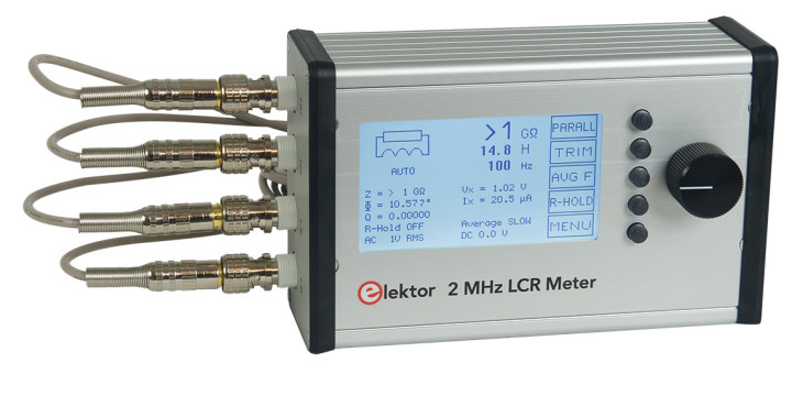
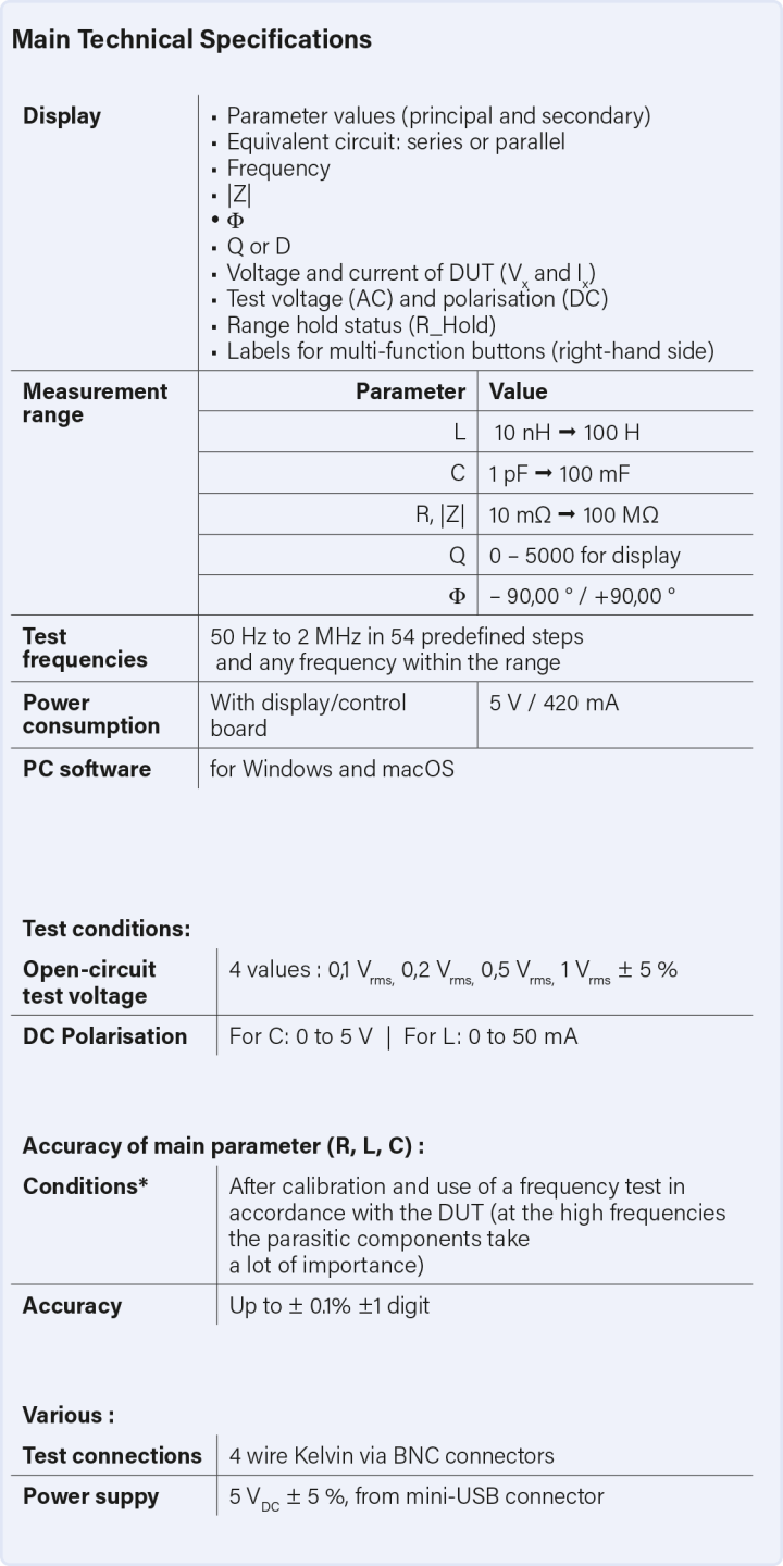
Only with your support The specifications of the LCR Meter are summarised in the below table. Before we start production of a kit, Elektor has launched a support campaign to gauge interest. If you would like to get your hands on a kit you can register, without making any formal commitment, online. The production of the kit will be started as soon as we have registered
The new LCR Meter features:
- Test frequency from 50Hz to 2MHz.
- 4 possible test voltages (100mV, 200mV, 500mV and 1V rms).
- Additional DC polarization up to 5V for capacitors and 50mA for inductors.
Particular attention has been paid to its ease of implementation (calibration) and use (a rotary encoder is used to navigate through the menu and to change the frequency).
LCR Meter AU2019
Overview
The impedance (Z) is an important parameter to characterize passive electronic components (resistance, capacitor, inductance). It is a complex number which can be represented by a real part (R) and an imaginary part (X) such that Z = R + jX, or in polar form by the modulus of its impedance and the phase shift between voltage and current: Z.
To determine an impedance it is therefore necessary to measure at least two values (in magnitude and in phase), generally the voltage at the terminals of the component and the current flowing through it. The LCR Meter AU2019 uses the self-balanced bridge method with the use of a simple operational amplifier for the current/voltage converter (I-V converter, see Figure 1).
This simple method provides good measurement accuracy at a reasonable cost. Its main disadvantage is a frequency range limited in the high frequencies by the performance of the operational amplifier used.
To obtain a wide impedance measurement range (a few tens from mΩ to more than 100 MΩ) it is necessary to switch the precision resistor (R) used in the I-V converter. Unfortunately, common analog integrated switches (such as 74HC4052) introduce parasitic elements (mainly capacitors) which also limit the performance at high frequencies. This is why most similar instruments have a high frequency limited to 100 (see 200) kHz.
It is however possible, by an original design and the choice of high-performance components, to push the high frequency to 2 MHz without an exaggerated increase in cost, and while keeping the simplicity of realization.
The chosen solution is not to switch the 4 measuring resistors (thus reducing parasitic capacitance to a minimum) but to have four Amplifier + Resistor pairs, each selected according to the impedance to be measured.
The operational amplifiers used (AD8099 from Analog Devices) have a cut-off frequency of approx. 200 MHz at an output voltage of 2 V p-p and have the necessary muting control. The switches are PhotoMOS manufactured by Panasonic with a very low product (ON resistance x output capacitance).
Another important point is the choice of the method of generating the test frequency. It is easy and inexpensive today to use Direct Frequency Synthesis (DDS) components, with the advantage that any frequency in the 50 Hz / 2 MHz range can be generated. It is, moreover, easy to generate for the synchronous detector a signal of the same frequency, but with variable relative phase, thanks to a second DDS circuit synchronized to the first.
The user interface is reduced to a strict minimum:
To determine an impedance it is therefore necessary to measure at least two values (in magnitude and in phase), generally the voltage at the terminals of the component and the current flowing through it. The LCR Meter AU2019 uses the self-balanced bridge method with the use of a simple operational amplifier for the current/voltage converter (I-V converter, see Figure 1).
This simple method provides good measurement accuracy at a reasonable cost. Its main disadvantage is a frequency range limited in the high frequencies by the performance of the operational amplifier used.
To obtain a wide impedance measurement range (a few tens from mΩ to more than 100 MΩ) it is necessary to switch the precision resistor (R) used in the I-V converter. Unfortunately, common analog integrated switches (such as 74HC4052) introduce parasitic elements (mainly capacitors) which also limit the performance at high frequencies. This is why most similar instruments have a high frequency limited to 100 (see 200) kHz.
It is however possible, by an original design and the choice of high-performance components, to push the high frequency to 2 MHz without an exaggerated increase in cost, and while keeping the simplicity of realization.
The chosen solution is not to switch the 4 measuring resistors (thus reducing parasitic capacitance to a minimum) but to have four Amplifier + Resistor pairs, each selected according to the impedance to be measured.
The operational amplifiers used (AD8099 from Analog Devices) have a cut-off frequency of approx. 200 MHz at an output voltage of 2 V p-p and have the necessary muting control. The switches are PhotoMOS manufactured by Panasonic with a very low product (ON resistance x output capacitance).
Another important point is the choice of the method of generating the test frequency. It is easy and inexpensive today to use Direct Frequency Synthesis (DDS) components, with the advantage that any frequency in the 50 Hz / 2 MHz range can be generated. It is, moreover, easy to generate for the synchronous detector a signal of the same frequency, but with variable relative phase, thanks to a second DDS circuit synchronized to the first.
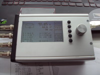
The user interface is reduced to a strict minimum:
- 240 x 128 pixel LCD graphic display.
- 5 push buttons.
- A rotary encoder with auxiliary contact.
The power supply is done through a Mini-USB connector: use of a smartphone charger, an external battery (for smartphone) or connection to a computer (this last connection will also allow Firmware update).
It is also possible, but not recommended, not to use the integrated user interface, but to use only a suitable PC program.
Main Board
Input Circuit (Figure 2)
The measurement is carried out with a 5-connection configuration [1] to minimize the influence of the measuring cables. Connectors J4 (High Drive) and J7 (Low Drive) supply power to the DUT (Device Under Test), while connectors J5 (High Sense) and J6 (Low Sense) allow the voltage to be measured as close as possible to the DUT. If a bias voltage is applied, the positive appears at J4/J5.
The PhotoMOS relays U54 to U57, which allow the operational amplifiers U9 to U12 to be connected, have an ON resistance of about 1 Ohm, so the voltage measurement must be made at the terminals of the DUT and not with respect to ground. This is the role of the differential amplifier built around U7A, U7B, U7C. It must have a high common mode rejection rate (CMRR) whatever the frequency. An adjustment is therefore necessary, first by R31 for the low frequencies (10 kHz), then by C44 for the high frequencies (1 MHz). The integrator built around U27B allows an automatic offset adjustment.
According to the measurement range, one of the operational amplifiers U9 to U12 is selected: pin DIS/ at high level and ON switching of the associated PhotoMOS (at input from U54 to U57 and at output from U50 to U53) by one of the signals SW1 to SW4 at low level.
The signals SW5 (control of U59) and SW6 (control of U58) allow to send to the measuring circuit either the output voltage of U7C (DUT voltage) or the output voltage of the I-V converter (image of the DUT current).
The application of a DC bias on the DUT is made at the level of the sinusoidal generator by an offset of its offset from 0 to 5V. As a 100 Ohms resistor is connected in series with the output of this generator, this will also correspond to a current of 0 to 50 mA if the DUT is a DC low resistance inductor. For a voltage across a capacitor, the U7D tracker allows pre-compensation at the differential amplifier for voltage measurement. For a current through an inductance, it is absorbed by the direct current source formed around Q8 and Q9. The integrator built with U27A ensures a DC voltage at the output of the I-V converter close to 0V.
To make the calibrations, precision resistors identical to those used for the I-V converters can be connected by means of a jumper (J10 to J13).
Sine Generator (Figure 3)
The generator is built around the U24 circuit (DDS AD9834 circuit from Analog Devices). Its 27 MHz clock is provided by the Y1 oscillator.
Its output (two signals in phase opposition) is filtered then amplified by U26A, U26B and U26D. The amplifier U26C allows an offset voltage to be applied. Without it, potentiometer R146 is used to adjust the offset of the sinusoidal signal (measured in TP7).
The phase detector used requires a perfectly square signal, at the same frequency as the generator, but whose relative phase can be varied. This is obtained by the U25 circuit (also a DDS AD9834) operating at a double frequency and followed by a fast comparator (U28) which drives a divider by 2 (U30 flip-flop).
PGA (Programmable Gain Amplifier) (Figure 4)
A first amplifier, consisting of U19 and U23, with a gain of 1, 2, 5 or 10, compensates for the reduction of the useful signal when the amplitude of the test signal decreases. Since its gain is not changed during a measurement cycle, its frequency response is not very significant.
The next stage consists of switching on either U20 for a gain of 1, or U21 for a gain of 3 (3.17 to be exact), or U22 for a gain of 10 (10.1).
U21 is frequency compensated by the setting of C108 and U22 by that of C51. The calibration procedure will take into account the real response of this PGA, for each of the frequencies used.
PSD (Phase-Sensitive Detector) (Figure 5)
This circuit is built around the two analog switches U41 and U42 which allow to connect a capacitor to the input signal during half a period, and to an integration capacitor during the other half period. The two switches operate in phase opposition in order to obtain a doubled differential voltage which can be used by the analog-to-digital converter U43.
The relative phase of the switch signal to the sine generator allows measurements of the in-phase or quadrature components of the input signal to this PSD.
The time constant for the storage capacitor is adjusted according to the measurement frequency: eight values are possible by selecting one of the resistors R121, R122, etc. via U70. An offset of 2V is applied to the input of U37 so that the signal remains at most within the constant resistance range of the analog switches (linearity problem of this PSD). When searching for the optimal measurement conditions (choice of I-V converter and PGA gain) the fast comparator U31 detects any signal overshoot above 2V peak, and sends this information to the MCU (start of an interrupt routine).
MCU (Micro-Controller Unit) (Figure 6)
The brain of the device is entrusted to a Silicon Labs MCU type C8051F120.
Why this type of relatively old circuit compared to modern MCUs with ARM architecture?
- It is sufficient in terms of integrated peripheral circuits and its programmable Flash memory (64k + 64k).
- The best microcontroller is the one we know well !...
- I already have the development tools !
Its internal oscillator (24.5 MHz) + PLL (coefficient 3) is used to have a clock frequency of 73.5 MHz.
Connector J15 (JTAG) allows to connect a USB Debug Adapter from Silicon Labs (e.g. RS part no. 757-0297) to flash the Bootloader in the EEPROM.
Connector J14 is used to connect the Display expansion board.
The LED D12 is used during program setup (e.g. when a button is pressed or when the encoder is operated) and also to signal certain error conditions :
- No interface connected on J14 and no communication via USB: permanent flashing 0.5s on and 0.5s off.
- Error during power supply test: in addition to the error number message, permanent flashing 0.5s on and 1s off.
Circuits U66 and U67 allow synchronization with the sinusoidal signal of the voltage and current measurements of the DUT.
A jumper on connector J16 informs the Bootloader of an unconditional firmware update request.
The push button K1 (RESET) is optional (it is only used during the development phase).
USB Controller and Power Supplies (Figure 7 and 8)
An FT232RL (U2) circuit from FTDI serves as a USB/UART interface to the MCU. Normal power is supplied through the USB connector (J1), although it is possible to supply power through the J2 connector by putting a jumper between 1 and 2 of J3 instead of 2 and 3.
Four voltages are required to supply all circuits:
- A V_BOOST voltage of +6.5 V or +7.5 V (depending on the level of the MAX_BOOST command) supplied by the step-up regulator U3 associated with L7 and D3.
- A voltage of +5V supplied by the linear regulator U4.
- A voltage of +3V supplied by the linear regulator U5.
- A voltage of -5V supplied by the inverter regulator U6 associated with L8 and D4.
All these voltages are checked by program at start-up (use of the 12-bit ADC and the multiplexer integrated in the MCU).
Display board (Figure 9)
A cable connected in J1 allows to link this board to the main board.
The 5 pushbuttons K1 to K5 and the SW1 rotary encoder pushbutton are matrixed to use only 3 Port lines at the MCU. The rotary encoder also uses 2 port lines.
RC circuits are used to perform a first debounce filtering to simplify software filtering.
Diodes D12 and D13, by triggering an interrupt routine at the MCU, inform the internal program that a button has been pressed.
The graphic display U1 is supplied with +3V (linear regulator U2) from the filtered USB voltage. Its backlighting is controlled by transistor Q1 and transistor Q2 allows, when the unit is switched off, a fast discharge of the internally generated VLCD voltage, avoiding an unpleasant visual effect.
This display card is identified, at start-up, by the presence of a resistor to ground (R7 in series with R9) on pin 19 (BKL) of J1.
Note
An expansion card with a Bluetooth Low Energy (BLE) module is being tested, identified by a 1 kOhm resistor connected between pin 6 (CONFIG2) of J1 and ground.
----------------------------------------------------------------------------------------------------------------------
50 Hz – 2 MHz Elektor LCR meter
Only with your support The specifications of the LCR Meter are summarised in the below table. Before we start production of a kit, Elektor has launched a support campaign to gauge interest. If you would like to get your hands on a kit you can register, without making any formal commitment, online. The production of the kit will be started as soon as we have registered
150 confirmations of interest. In exchange for your early commitment you will be offered the kit at a reduced price.
The LCR Meter kit will include
The LCR Meter kit will include
- Main board preassembled with all SMD components soldered
- Display board preassembled with all SMD components soldered
- Through-hole components for both printed circuit boards (backlit graphic LCD display, connectors, push buttons, rotary encoder, button)
- Ribbon cable to connect the main board and display board
- Mini-USB cable for connection to PC and software updating
- Aluminium Hammond case, drilled and milled panels
- Screws
- Kelvin clip with test cable with four BNC plugs
- Manual
Discussion (96 comments)


David Nass 5 months ago
Hi everybody
I finally got LCR Hardware properly soldered. Connencted alltogether and flashed the MCU with the LCR6-Bootloader.hex and the LCR6.hex . The MCU starts and displays <BOOTLOADER V 1.6> and than I get a clear screen with background light. I've also tried ther MergedLCR6.hex. Nothing happens afterwards.
I'm using a USB Debugger connected to J15 and Silicon Labs Flash Programmer Utility. Downloading of the hex files works properly. Does anyone have an idea what I'm doing wrong?
Reply
Show more
2 Attachment(s)
1 Comment(s)

ProstetnikJeltz 6 months ago
Hi,
for those, who might build the LCR from the scratch like me, it might be useful, to have an overview, which parts goes where and what is already placed and what is missing.
I'm using KiCAD and the interactive bom, attached here.
It's a html, which runs at least with Chrome, where you can see, which part goes where on the PCB and there are checkboxes for parts sourced and parts placed.
You can also export the list to Excel and make your own BOM.
Have fun and good luck
Uli
Reply
Show more
2 Attachment(s)
0 Comment(s)
ProstetnikJeltz 7 months ago
Hello,
I'm experiencing, that the VUSB is not switched via Q1.
I understand that the following way.
CBUS4 (#SLEEP) from U2 (FT232RL) should go high, when U2 is powered by USB.
This switches Q2 and that pulls the gate of Q1 to ground, so that VUSB is switched.
At my board (diy) I see, that CBUS4 goes high for 300-500ms and then tranits to zero.
I guess, the FT232 goes to sleep so fast, because there is no traffic seen in a serial monitor.
The CBUS4 is assigned to #SLEEP in the FT's E²PROM.
The LED (D12) of the MCU is blinking, so the processor should work and communicate (the display board isn't attached yet, because the LCD is not available until Oct. 2024 at Farnell).
How can I get the FT232 to stay active?
Best regards
Uli
Reply
fraubrj 6 months ago
Hello,
This sounds like a problem we've already encountered when the USB power supply we've using doesn't fully comply with the standard.
Try another power supply (and / or another USB cable)!
Best Regards,
Jean-Jacques
This sounds like a problem we've already encountered when the USB power supply we've using doesn't fully comply with the standard.
Try another power supply (and / or another USB cable)!
Best Regards,
Jean-Jacques
Reply
ProstetnikJeltz 6 months ago
Hello Jean Jaques,
thank you very much for the hint, it was really the Power supply I used.
It is rated 2A, but the voltage drops below 4.7V @350mA.
Now I power the board via the pin socket and it works some kind.
Next problem is, that I have absolutely no communication between the FT232 and the processor.
The RX LED blinks, when I send a command to the board via GUI, but there is no TX from board to the PC.
I presume, that the FT232 has an issue and will replace it soon.
TX/RX are conductive from FT to µC.
Best regards
Uli
Reply
Show more
1 Comment(s)
ProstetnikJeltz 9 months ago
Hello,
unfortunately the kit wasn't/isn't available for a longer time.
That was the reason for me, to built the LCR-meter by my own, because everything we need is provided.
No, just NEARLY everything.
Got all the parts at LCSC, Farnell, Mouser, Digikey ... and started to solder and nearly gave up at the first capacitors.
Due to not being searchable, the provided pdf's make it harder than easier.
I started with the 100nF capacitors C1.... (50 in total) and needed 10 minutes to find - for example - C28 because it is situated on a completely other part of the PCB than, let's say, C24.
If the pdf's were searchable, the C28 would be highlited, now it's playing hide and seek.
I don't want to waste several hours for searching the right position - for 50 capacitors, and I guess, it's getting worse.
I know, that diy needs more time, but you don't have to deliberately make things harder for yourself than necessary.
I'm used to solder my own projects (and I did plenty) using the tool "InteractiveHtmlBOM (V2.9.0)", which is available EasyEDA, Eagle, KICAD, Fusion360 and Allegro - unfortunately not for Orcad - maybe there is another solution.
There you have your BOM and all the positions highlited in a browser window.
Unfortunately converting your provided pdf's with OCR doesn't work, they are still nor searchable.
Also printing the gerbers as pdf is not working, for being searchable.
If you could provide the Schematics in a common CAD-Format like Altium, Eagle, KiCAD, EasyEDA ... it would help a lot.
Otherwise I have parts, worth 250€+ and really no will, to start this "seeking for the position"- game, wasting so much time.
I was of the opinion that a self-build project supported by Elektor would be better supported.
What a pity ...
Please forgive me my direct words, but at the moment I'm really pi...ed!
Best regards
Uli
Reply
fraubrj 8 months ago
Hello,
I'm sorry, but I don't have a real solution for using the published pdf and gerber files to find where a particular component is located on the PCB.
One solution is to go backwards:
- identify a component on the PCB (for example Q2)
- use the BOM to find out which component it is.
(you can use EXCEL's search function in the xlsx file).
Another solution is to use the ORCAD “Pick and Place” file, which is used to place components on the PCB (with the placement machine).
- for Q2 you'll find:
Q2= ( BSS123,,,,34.94,146.23,270,TOP), i.e.
Ref. of component “BSS123
X = 34.94 (mm)
Y = 146.23 (mm)
orientation (270°)
On TOP.
With PCB positioned vertically and BNC connectors down, coordinate origin (0,0) is bottom left.
I attach the files (BOM and LCR6 PICKNPLC files)
Best Regards,
Jean-Jacques
Reply
ProstetnikJeltz 8 months ago
HI,
sorry for replying so late, but I haven't got a reminder, that there is an answer.
Thank you very much.
Anyway, I found a solution, which is partially completed by now.
I copied the Gerbers and built a completely new PCB using KiCAD with the same placement and - of course - the same references to the parts.
Attached you will find a html - the function speaks for itself.
It works with Chrome, other Browsers were not tested.
I hope, there are less or no errors in it - feel free to use it and please report any issues to me, so I can improve that.
Jean-Jaques, when you are ok with that, I would also put the KiCAD-Files here, but they are not finished yet.
I just placed the parts, but didn't route the PCB by now.
Best regards and again thank you very much
Uli
Reply
Show more
1 Comment(s)

wanghar 2 years ago
Hi Jean,
Thank you for publishing thus a great project! It spent me 2 months of time to collect all the components on BOMs and a set of PCBA(main board + display board) has been assemblied up and powered up successfully.
So far, it works good at 1Vrms level with good accuracy for most of the frequency setting in firmware even up to 1.5MHz and 2MHz. However, for 0.5V/0.2V/0.1V rms conditions respectively, I see a big deviation from the 1Vrms measurement values. For example, @100KHz , a 100.0 K ohm(0.1%) resistor is read as 92.55K ohm at 0.5Vrms while it read as 99.98Kohm at 1Vrms. Calibration and trim is well done based on the operatoon instruction.
I am wondering if I miss some thing to cover all the test conditions, particularlly additional calibartion jobs needed but I get it ignore?
Thanks again for your sharing the big program!
Harvey
Reply
fraubrj 2 years ago
Hi Wanghar,
What you see is real and despite many hours spent observing the various signals with an oscilloscope, I do not have a formal explanation for this phenomenon.
Due to the presence of switching power supplies on the PCB, the signals to be measured are quite noisy, and the influence of this noise increases when the signal level decreases and the impedances to be measured increase!
This is why this phenomenon is mostly visible in range 4, less in range 3 and 2 and not very sensitive in range 1.
Fortunately the calibration procedure allows to take this into account.
With the current version of the firmware (version 3.x.y) this calibration is done with a 1V RMS signal.
I have upgraded this firmware to version 4.0.0 with which I have added calibrations for the levels 500mV, 200mV and 100mV, this for the ranges 1 to 4.
To use it, it is necessary to redo all the calibrations and delete the old ones. So when updating the firmware (with the AU2019 program), do not forget to answer YES to the question "Erase the Calibration Datas?
Then redo all calibrations as described in the documentation.
Then, change the "AC level" and do the calibrations of ranges 1 to 4 for 500mV, 200mV and 100mV.
This is very time consuming!
The lack of memory space does not allow the same thing to be done for the TRIMs, but this is less important and it is always possible to do the two TRIMs at the chosen frequency.
Attention, this firmware (version 4.0.0) is experimental and the return to a firmware version 3.x.y will oblige to erase again all the calibrations and to redo them with the 1V RMS level.
Reply
wanghar 2 years ago
Hi fraubrj ,
Thank you for your reply and upload the updated hex file! I will test the new firmware when time is available in this week.
Just as what you pointed out in the reply that there is some issues with the range 4. I tested with a 2M
ohm resistor(0.1%) at range 4 and get the measurement of 1.95xM ohm while I get 1.99xM ohm at range 3. Obviously range 3 has a much better performance than range 4, but this result is quite contrary to the expectation! Actually a big error will seen when the measured impedance is greater than 1M ohm at whatever 1KHz,10KHz and 100KHz when range 4 is used. This makes range 4 discount its performance significantly. This issue seems quite related to the hardware design around input circuit of range 4 and some modification is really needed.
I also took some investigation on the performance difference on levels of 500mV, 200mV and 100mV and found the differnce has something to do with U19(LMH6618)'s state. In brief, when U19 switches to the status of a gain greater than 1 noisy signal could be observed( by an oscilloscope ), this also one of the reason why 500mv/200mv/100mv do not perform so good in addition to the reason of lack calibration. After I cut 2 traces and add 2 combination of 100nf de-coupling caps and ferrite bead for both +5V/-5V power sources for U19 the result improves a lot. This is just a hint for some problem solving.
Thanks again for you taking so many hours to prepare the reply to my note! And I am glad to share you my progress if I have any here!
Reply
Show more
1 Comment(s)

JRS 2 years ago
Recently I received your Au2019 LCR meter.
Does there exist any document that describes the best possible accuracy obtained , recarding the used measuring- conditions like sort of component L/C/R, sort of measurement C/L/R/Rs/Q , Frequency/Impedance , serial/Parallel etc.
I can think for myself, but i like to hear about this from others.
I found that , after a complete calibration , wittch the clips open, in parallel the measured capacity was close to zero, but in series the mesured capacity was several pF's, correct ?
Reply

Jean-Jacques Aubry 2 years ago
Hello JRS
Concerning the precision of the measurements it is important to understand how this device works.
4 quantities are measured:
- the voltage across the DUT (Vp -> in-phase component, Vq -> quadrature component)
- the current flowing through it (Ip -> in-phase component, Iq -> quadrature component)
The current itself is calculated by measuring the voltage across the I-V converter resistance, i.e. that at the output of the selected AOP (U9...U12) divided by the value of this resistance.
The model used is simple: a resistance and a conductance in series
Z = Rs + jXs
Rs = (Vp x Ip + Vq x Iq) / (Ip x Ip + Iq x Iq)
Xs = (Vq x Ip - Vp x Iq) / (Ip x Ip + Iq x Iq)
Corrections, to take into account the parasitic components of the measurement chain, are then applied:
- those specific to the components used on the circuit, which are not perfect, and to the PCB (importance of calibration)
- those specific to the test fixture (importance of OPEN-CIRCUIT and SHORT-CIRCUIT corrections)
These corrections are somewhat temperature dependent, and it is important to let the instrument stabilize after start-up.
Also, do not hesitate to redo the calibrations from time to time!
Regardless of the accuracy of the measurements, errors are introduced by these calculations, for exemple when two adjacent quantities are subtracted.
Another important point regarding accuracy is the range of validity of the chosen model. This is where the frequency of measurement must be chosen carefully and the test fixture must be well adapted. Read carefully the comments in the Update from the author section, especially "Trying out some test fixtures".
Reply
Show more
1 Comment(s)

Olivier_ 2 years ago
Update: Q7 is functional and correctly brought to conduction upon start up - V_BOOST consequently jumps from 6.5V to 7.5V. Solder redone for R69 and R129.
------
Hi,
On and off upon powering the LCR meter on I get the following error message: "PS Test Error, code 16" which seems to be corresponding to an error in the 7.5V PS.
I checked my board and all voltages are within tolerance (+5V, -5V, +3V, and +6.5V)
I am powering up from USB. Cable has been changed.
Can someone tell me why this happens please?
Thank you.
Reply
Show more
0 Comment(s)

Luca Fusari 2 years ago
I would like to understand how to connect the bluetooth PCB to my main board Rev 2.5.
Thanks
Luca
Thanks
Luca
Reply
fraubrj 2 years ago
Sorry to answer so late, but I was very busy with a move!
The bluetooth PCB connects to the J14 connector on the main board, instead of the display board. The DSD TECH HM-10 BLE module protrudes slightly from the case so that the antenna is outside the case. This requires an additional cutout in the USB side! The mechanical drawing can be found in the archive 190311 AU2019 BOM Gerbers PDFs Enclosure 2021-10-08.zip, folder Case drilling and milling - FrontDesign / Face USB Rev1.fpd.
Some explanations on its use can be found in the document LCR Meter AU2019 - EN Communications Rev 6b.pdf (in the archive 190311 AU2019 DOC EN & FR 2021-10-09.zip
Reply
Show more
1 Comment(s)
Olivier_ 2 years ago
Hello,
A big thank you to Mr Aubry for this great project and the interesting articles published!
I am looking forward to receiving my kit.
I wanted to know if it would be better to use a special adapter for SMDs similar to the one you have tested for discrete components or if a SMD tweezer would be ok (we find a lot inexpensive ones but I wonder the quality..)?
Last, I took some time to upload most of the BOM on my favourite websites; the total cost reaches around 450EUR to which one needs to add the cost of the enclosure customisation and the PCBs manufacturing. A few components are still on back-order due to the current situation though.. After what one needs to solder the 500 components and test the card; so as a conclusion thank you Elektor for the kit :)
Regards,
Olivier
Reply
Show more
0 Comment(s)

EN0182892ID 2 years ago
HI
Could you provide protocol to control LCR Meter(AU2019)?
Best Regards
Could you provide protocol to control LCR Meter(AU2019)?
Best Regards
Reply
Jean-Jacques Aubry 2 years ago
Hi EN01828921D,
The messages exchanged between the device and the PC program (AU2019) are described in the document LCR Meter AU2019 - EN Communications Rev 6b.pdf in the archive 190311 AU2019 DOC EN & FR 2021-10-09.zip.
The AU2019 (Qt) program sources files are in the archive 190311 AU2019 Files & Code DOWNLOAD 2021-10-06.zip : AU2019 - programs for the different platforms / AU2019 V 1-3-3 Qt source files (macOS, Windows7, Ubuntu)
Reply
EN0182892ID 2 years ago
Hi, Jean-Jacques Aubry
I have 3 Question?
1. When the power is restarted, I have to written command "START" to enter the PC mode, but this command will transmit a large number of current screen reading values. Is there a way to issue the START command without transmitting a large amount of data?
2. How to detect the current firmware version, the F_VERS written in the manual has no effect.
3. When I written "RUN" command can read all test value, whether can to read the read value of a single field?
Best Regards
Reply
Jean-Jacques Aubry 2 years ago
Hi EN01828921D,
Can you tell me how you communicate with the device?
As explained in the "LCR Meter AU2019 - EN Communications Rev 6b" document, it is important to respect the syntax of the messages sent to the device (termination by 'End of String' or 'End of Line' or 'Carriage Return' or '/' character).
Best Regards
Reply
Show more
1 Comment(s)

EN0183901ID 2 years ago
Hi,
I have one more question, I would like to create a boost or buck converter on MATLAB. I am wondering how to make a model of the capacitor and inductor by using parasitic elements. I mean, how to merge parallel and series measurements into one schematic? Is it possible for you to provide a model drawing?
Regards
Reply
Show more
1 Comment(s)
EN0183901ID 2 years ago
Hi Everyone,
It's the first time that I am using an LCR meter. But I am having trouble of reading capacitor values(capacitance) with higher frequencies over 10khz. It either shows only inductor and resistor value or very low capacitance value. Have any idea what the problem might be?
Regards
It's the first time that I am using an LCR meter. But I am having trouble of reading capacitor values(capacitance) with higher frequencies over 10khz. It either shows only inductor and resistor value or very low capacitance value. Have any idea what the problem might be?
Regards
Reply
Jean-Jacques Aubry 2 years ago
Hello EN0183901ID,
Can you tell which capacitors you are measuring: supposed value, type (ceramic, film, electrolytic...)?
Best Regards,
Jean-Jacques
Can you tell which capacitors you are measuring: supposed value, type (ceramic, film, electrolytic...)?
Best Regards,
Jean-Jacques
Reply
EN0183901ID 2 years ago
Hi Jean-Jacques,
Thank you for your swift reply. I am measuring electrolytic capacitors. I tried many different electrolytic capacitors and got the same results. I don't have much theoretical knowledge about measuring with lcr meters. So, I hope i am not doing wrong measurements. I tried to measure 100uf 400V, 10uf 50V, 1000uf 25V and 2200uf 100V. An example of 100uf 400V on the attached picture.
Thank you for your swift reply. I am measuring electrolytic capacitors. I tried many different electrolytic capacitors and got the same results. I don't have much theoretical knowledge about measuring with lcr meters. So, I hope i am not doing wrong measurements. I tried to measure 100uf 400V, 10uf 50V, 1000uf 25V and 2200uf 100V. An example of 100uf 400V on the attached picture.
Reply
fraubrj 2 years ago
Hello EN0183901ID,
Here is my answer to a question from Eraysor (8 months ago):
The device measures two complex quantities, the voltage across the DUT (V) and the current through it (I). It then calculates the complex impedance Z = V/I.
...
Then a simple 2 component model is used to display the primary and secondary parameters.
...
If the DUT, at the test frequency, is better represented by a more complex equivalent diagram, it is certain that the values displayed for these last two parameters are wrong! But Z is always valid.
This is why measurements should be made for inductances, and also for large electrolytic capacitors, at frequencies << their resonant frequency.
This is the problem when measuring electrolytic capacitors at frequencies > 10 kHz, because the design with wound foils gives a very high parasitic inductance, thus a low resonance frequency. And beyond this frequency it is no longer a capacitor!
This is why other types of capacitors should be used in switch mode power supplies (film, ceramic, electrolytic with low capacitance in parallel...)
Jean-Jacques
Reply
Show more
1 Comment(s)
EN0182892ID 2 years ago
Could you share keil C51 V9.60 setting parameter
Best Regards
Best Regards
Reply
Jean-Jacques Aubry 2 years ago
Hello EN0182892ID,
Sorry, but I don't use Keil's development environment directly, but Silicon Labs' one, incorporating Keil's tools!
This is described in the document "LCR Meter AU2019 - EN Changing the code Rev 1c.pdf" that you can find in the archive "190311 AU2019 DOC EN & FR 2021-10-09.zip"
Here are my parameters for the Silicon Labs IDE:
Best Regards
Reply
Show more
4 Attachment(s)
1 Comment(s)

DE164277 2 years ago
Dear Mr. Aubry,
for years I have been an enthusiastic user of the 500 ppm LCR meter.
Although I own the hardware revision 4 with the changes from 11/2013 and the software Ver. 3.0.0.
Nevertheless, the LCR meter crashes again and again when measuring small resistances. Do you have a hint for me what I can do about it?
Many thanks and Best Regards
Hartmut
PS: Unfortunately, the forum on the 500 ppm LCR meter is no longer available, hence my question at this point. Please excuse that.
Reply
Jean-Jacques Aubry 2 years ago
Hello,
The latest firmware is version 3.1.1
Try it, I hope it will solve your problem!
The latest firmware is version 3.1.1
Try it, I hope it will solve your problem!
Reply

ssm mil 2 years ago
LCR3A_firmware_V311.hex file seems corrupted [ file size 17,280 bytes ] , cannot get passed bootloader. Loading the oldest LCR3A_firmware_V310.hex works just fine [ file size 120,345 bytes ] .
Reply
Jean-Jacques Aubry 2 years ago
Sorry, here is the right file
Reply
DE164277 2 years ago
Dear Mr. Aubry,
unfortunately, the problem persists and, in my estimation, has even gotten worse with the new firmware.
The display initially shows confused patterns, sometimes regular stripes. After that, it goes out completely and shows nothing more (only the backlight is active).
This occurs especially when you touch the measuring channels with your finger.
Do you have a hint for me?
Many thanks and Best Regards
Hartmut
Reply
Show more
1 Comment(s)

Alvin 2 years ago
[Problem Solved] Mr. Aubry , Appreciate your great job and sharing!
After I loaded the Bootloader + Firmware ( file MergedLCR6.hex ). First time to start the device, the lcd show the ''No language loaded...''
I can go to to the PC mode by the AU2019, but can not update the Texts. Confused... seemed something wrong. Why not combined the Texts into the Hex file?
After I loaded the Bootloader + Firmware ( file MergedLCR6.hex ). First time to start the device, the lcd show the ''No language loaded...''
I can go to to the PC mode by the AU2019, but can not update the Texts. Confused... seemed something wrong. Why not combined the Texts into the Hex file?
Reply
Jean-Jacques Aubry 2 years ago
The MergedLCR6.hex file contains the program code (Bootloader + Firmware). It is this code that makes the measurements and all the calculations and then displays the results.
In the "Standalone" mode the interaction with the user is guided through Menus, and in order to facilitate the understanding of the latter it is possible to choose a language (English, French, German...). These messages are contained in a text file that is relatively easy to modify, for example, to add a language. See the file "LCR Meter AU2019 - EN The text file Rev 4a.pdf" (contained in the archive "190311 AU2019 DOC EN & FR 2021-10-09.zip" that you can download at the end of the section "Updates from the author"). So it is the file "LCR6 Texts v3.txt" (it is in the same place) that you have to use. To do this, in "PC mode", launch the AU2019 program (the one adapted to your PC can be found in the archive "190311 AU2019 Files & Code DOWNLOAD 2021-10-06.zip", folder "AU2019 - programs for the different platforms") and connect it with the device (Port menu ... see the documentation...) Then Menu Settings/Texts update and choose the file "Texts LCR6.txt".
In the "Standalone" mode the interaction with the user is guided through Menus, and in order to facilitate the understanding of the latter it is possible to choose a language (English, French, German...). These messages are contained in a text file that is relatively easy to modify, for example, to add a language. See the file "LCR Meter AU2019 - EN The text file Rev 4a.pdf" (contained in the archive "190311 AU2019 DOC EN & FR 2021-10-09.zip" that you can download at the end of the section "Updates from the author"). So it is the file "LCR6 Texts v3.txt" (it is in the same place) that you have to use. To do this, in "PC mode", launch the AU2019 program (the one adapted to your PC can be found in the archive "190311 AU2019 Files & Code DOWNLOAD 2021-10-06.zip", folder "AU2019 - programs for the different platforms") and connect it with the device (Port menu ... see the documentation...) Then Menu Settings/Texts update and choose the file "Texts LCR6.txt".
Reply
Show more
3 Attachment(s)
1 Comment(s)

raymondlamwu 2 years ago
all of file are here, can I make one for myself without buying the kit? I am trying to purchase componet , pcb etc. Can I do that ?
Reply
Jean-Jacques Aubry 2 years ago
Yes of course!
But be aware, as mentioned in the first article under PCBs (Figures 14a, b & c) you need a lot of experience to assemble very small surface mount components (resistors and capacitors in size 0603)!
Don't expect to make any money because you have to buy the components in small quantities at full price.
Moreover, at the moment some of them are not available because of the shortage of electronic components.
You need to own lab equipment like an oscilloscope... and buy the USB DEBUG ADAPTER from SiliconLabs (or similar to find on eBay) to load the Bootloader + Firmware ( file MergedLCR6.hex ).
You will also have to machine the case...
If you just want to have fun, read carefully all the documentations, updates, all the discussions...and good luck!
Reply
raymondlamwu 2 years ago
Danm, Nice guide and reply! Thks! For those 0201 0603 soldering,it is not an challenge for me.
But after trying to make small nrlc tweezers ,I realize I will need an better benchtop machine. I have some testing equipment(include oscilloscope ds2302a, 5 1/2 benchtop multimeter etc).
The biggest issue is component shortage considering condition nowadays. I will try to check all of the boms.
Thanks again buddy !
Reply
Show more
1 Comment(s)

Rolf Wiesner 2 years ago
Hello,
first, I'd like to know where to find the neu firmware 3.xx ? My actual version is 2.3.4
When I try to enter the calibration section by pressing the button a bit longer, and the screen did flicker short, the message "used saved frequency ?" is showing, but not the calibration menu.
This leads me to the question: Why is the calibration not reachable via the menu?
What am I doing wrong?
Reply
Jean-Jacques Aubry 2 years ago
Sorry to answer you late, but I was on a trip...
I guess the device is working normally but you can't calibrate it.
The easiest way is to do it in Standalone mode, that is to say without USB connection with the AU2019 program on the PC. To be sure to be in this mode, power the device from a smartphone power supply!
On page 12 of the Assembly Manual, there is a picture (16d) of the screen of a working device (in Standalone mode) before calibration. The button marked [MENU] (not the rotary encoder) allows access to the calibration menus with a long press.
Read carefully the instructions given on page 12 and the following pages.
You can also read the document LCR Meter AU2019 - EN Operating Instructions Rev 17.pdf which you will find in the archive 190311 AU2019 DOC EN & FR 2021-10-09.zip downloadable from the link at the end of the Updates from the author section.
The latest firmware (version 2.3.6) can be found in the archive 190311 AU2019 Files & Code DOWNLOAD 2021-10-06.zip
AU2019 - device programs 2021-10-06 / Bootloader and Firmware Hex files / LCR6-Version 2.3.6 / LCR6.hex.
The firmware update is done in PC mode using the AU2019 program.
Reply
Show more
2 Comment(s)

George Hamilton 3 years ago
Hi, I was wondering what's the reason of -5V power rail being isolated (through L8), unlike +5V and +3V. Thanks for your time.
Reply

FAROOQ AHMAD 3 years ago
Mr. Aubry, I would like to answer this rather simple question.
-5V is through a switching regulator and L20 might be a filter I suppose...L8 is part of switching circuit and is essential....
Best Regards
Farooq
-5V is through a switching regulator and L20 might be a filter I suppose...L8 is part of switching circuit and is essential....
Best Regards
Farooq
Reply
George Hamilton 3 years ago
Wow, what a "rather simple" reasoning... But the question is headed towards the use of dual inductor topology.
The answer turns out to be in the datasheet.
Greetings.
The answer turns out to be in the datasheet.
Greetings.
Reply
fraubrj 3 years ago
You are right, the answer is in the LT1611 datasheet:
"The LT1611 operates in a dual inductor inverting topology which filters the input side as well as the output side of the DC/DC converter."
L20 is part of an additional output filter.
"The LT1611 operates in a dual inductor inverting topology which filters the input side as well as the output side of the DC/DC converter."
L20 is part of an additional output filter.
Reply
FAROOQ AHMAD 3 years ago
Mr. Aubry, I have a qustion. Why not use the soft start of LT1611 always?
Best Regards
Farooq
Best Regards
Farooq
Reply
fraubrj 3 years ago
Hi Farooq,
This is a mistake on my part, because without being too careful I reproduced the soft-start circuit used in the 2013 version!
As noted in the "kit" paragraph of the "Updates from the author" section, if necessary, it is easy to modify the soft-start circuit to return to the official scheme (see image C20-modif.jpg).
Reply
Show more
1 Comment(s)

Tako Tamas 3 years ago
Hi, Just want to know, if I miss siomething here, as I do not get any usable results for capacitors (1-2uF MKP) or for coils (5-20uH) with measurement frequencies above 100kHz. When I check these parts with a GW Instek LCR meter capable to measure up to 10MHz, it can measure the values correctly however even in the MHz range…..
ANy of you getting usable values above 100kHz? What do I miss?
Thanks :-9
Reply
fraubrj 3 years ago
I think your problem is that you are using a Test Fixture that is unsuitable for frequencies > 100 kHz.
The Kelvin Clips supplied with the kit are too long, and should be shortened (maximum 30 cm).
The best is to use a GW Instek LCR-05 or a Tonghui TH26001A.
See the last page of 2 MHz LCR Meter Kit AU2019 Assembly Manual_v3.3 (download it in Update from the author).
Don't forget to redo the TRIM calibrations every time you change the Test Fixture.
The picture of the test of a small inductance of 47 µH at 500 kHz with 30 cm Kelvin Clips.
Reply
Show more
1 Comment(s)

sl95 3 years ago
Bonjour Jean Jacques,
Suggestions d'améliorations dans les menus listes : il serait plus aisé d'utiliser les menus en liste en les mettant en boucle - le cran suivant sur le dernier item passe au premier et inversement - au lieu de bloquer sur le premier ou dernier item.
est ce une importante modification ? je ne sais pas.
cordialement
Serge
Reply
fraubrj 3 years ago
Hello Serge,
The interest in changing the menu sequence as you suggest is very limited because it is only visible for the Calibration menu (Standalone mode). And this menu is only used from time to time.
But it is possible for someone who wants to do it because the source code is available at the end of the "Update from the author" section (archive 190311 AU2019 Files & Code DOWNLOAD 2021-10-06.zip).
Jean-Jacques
Reply
Show more
2 Comment(s)

Southerner 3 years ago
Are there any plans to offer files for a 3D enclosure for this?
Reply

Content Director, Elektor 3 years ago
Reminder: The Elektor LCR Meter kit comes with Hammond case -- 6.5 x 4.2 x 2.1" (166 x 106 x 53 mm) -- drilled, machined, with printed front and side panels. Here is an unboxing video. You can learn more about the kit on its Elektor Store page.
Reply
fraubrj 3 years ago
No 3D drawings!
Both PCBs are designed to be mounted in a Hammond case, part number 1455N1601. Follow this link https://www.hammfg.com/electronics/small-case/extruded/1455
and clicking on the reference 1455N1601 in the "Enclosures" table you will open a small window which allows you to download the documents related to this enclosure.
You will find the machining (in FrontDesign format) of the different sides in the file 190311 AU2019 BOM Gerbers PDFs Enclosure 2021-10-08.zip to be downloaded at the place indicated by Nice2Know. Look in the Case drilling and milling - FrontDesign.zip file.
Reply
Show more
2 Comment(s)

PAB 3 years ago
Mr. Aubrey, are those resistors intended to keep the gain of the IU converter below 1? I mean when you need to measure very low values of resistance, using the 100Ohm range resistor (R44 on U9).
Reply
fraubrj 3 years ago
These 3 resistors in series (100 Ω in total) allow to limit, when the DUT is of very low impedance, the load of the amplifier U26B which provides the sinusoidal test signal.
Moreover, when this DUT is a very low impedance inductor and a DC bias current of 50 mA is applied, the power to be dissipated in this 100 Ω resistor is about 250 mW, hence the split into 3 resistors each capable of dissipating 250 mW (at 70 °C).
Furthermore, this limits the gain of the I/U converter to -1, thus the voltage at its output.
Reply
Show more
1 Comment(s)
George Hamilton 3 years ago
I could see the whole signal path is DC coupled, but just before the PSD, C81 couples the signal with U37. Is it a blocking DC capacitor to isolate the 2V DC offset applied to U37? Doesn't it attenuate the measured signals at low frequencies?
Reply
Show more
1 Attachment(s)
1 Comment(s)

Mont Caballe 3 years ago
Dear Mr. Aubrey, taking a look at your previous version of this great project, I could see you chose a multiplying digital/analogue converter as PGA. That gave you a more flexible adjust of the gain to apply to the signal. Why did you change to a more "discrete" solution in this new version? Does it have to do with the frequency response?
Reply
fraubrj 3 years ago
Indeed I preferred to build the PGA from HF amplifiers because the datasheet of the DAC8811 (used in the 2013 version) does not give any information on the phase rotation with the frequency.
The simulation of this new PGA with LTSpiceVII shows that it is possible to have, after adjustment by the capacitors C51 and C106, a phase difference (even beyond 2MHz!) practically null between the 3 gains (1, 3, 10).
The simulation of this new PGA with LTSpiceVII shows that it is possible to have, after adjustment by the capacitors C51 and C106, a phase difference (even beyond 2MHz!) practically null between the 3 gains (1, 3, 10).
Reply
PAB 3 years ago
Mr. Aubry, and why did you choose the values 1,2,5,10/1,3,10? Is it just because they are typical values for a discrete PGA?
On the other hand, the previous version had 48 steps of gain. This new discrete implementation has only 12. Is it a drawback in any way?
On the other hand, the previous version had 48 steps of gain. This new discrete implementation has only 12. Is it a drawback in any way?
Reply
fraubrj 3 years ago
Two things must be separated:
1 - The amplifier built around U19 with a selectable gain of 1, 2, 5 or 10 is only used to compensate for the decrease in test signal amplitude (1V, 0.5V, 0.2V, 0.1V RMS). This gain is not changed between the current and voltage measurements of the DUT. Its bandwidth therefore does not need to be perfectly known.
2 - The PGA (U20, U21, U22) whose gain is modified during the measurements is more critical. It was not conceivable to make a high bandwidth PGA with more than 3 stages in discrete components. The maximum gain being 10, I chose an intermediate gain of 3.16 (the square root of 10). Then the ADC used (ADS1246 - 24 bits) has a built-in PGA with a selectable gain of 1, 2, 4, 8, 16, 32, 64, 128.
As explained in the article on the 2013 version, in order to obtain the highest possible accuracy (up to 0.02%) the signal to be measured by the ADC had to be adjustable as close as possible to its full scale. Hence the use of the DAC8811 allowing a very fine adjustment of the gain, but with a limited bandwidth.
Reply
Show more
1 Comment(s)
George Hamilton 3 years ago
Mr. Aubry, what's the use of BAV199 and V_Boost? Is it just a protection to avoid higher voltages (positive or negative) at the input of U7A?
Reply
fraubrj 3 years ago
When the bias voltage of a capacitor under test is set to its maximum (+5V) it is necessary to increase by 1V the positive supply voltage (V_BOOST) of the ICs U7 and U26 (normally at 6.5V) in order to guarantee their correct operation!
The diode D7 (BAV199) provides a slight protection against input overvoltage by clipping at V_BOOST for positive voltages and -5V for negative ones.
The diode D7 (BAV199) provides a slight protection against input overvoltage by clipping at V_BOOST for positive voltages and -5V for negative ones.
Reply
Show more
1 Comment(s)
Mont Caballe 3 years ago
Congratulations on such a great project! Dear Jean-Jacques, could you please tell me the objective of R35 and R36? I can see they connect HD with HS and LS with LD, but, what for? Thanks in advance.
Reply
fraubrj 3 years ago
When there is no test device connected, or during calibrations when there is no jumper on J8 and J9, these two resistors ensure that the HS and LS measurement inputs are not fully open, and that there is a path for the bias currents of the inputs of U7A and U7B.
Reply
PAB 3 years ago
That's right, but, shouldn't they be connected to ground?
Reply
fraubrj 3 years ago
No, absolutely not!
Read my answer to Nectoux68800 entitled Kelvin clips.
In normal use, the contacts of HD and LD on one hand, and LD and LS on the other hand, are connected together at the DUT, as shown in the image kelvin-clips.jpg.
Read my answer to Nectoux68800 entitled Kelvin clips.
In normal use, the contacts of HD and LD on one hand, and LD and LS on the other hand, are connected together at the DUT, as shown in the image kelvin-clips.jpg.
Reply
PAB 3 years ago
I fully understand that. What I meant, based in your answer to Mont Caballe, is that I can't see the return path of the dc input bias currents to ground, which I understand is the objective of those resistors, when there's no DUT connected. Can you point it out?
Reply
fraubrj 3 years ago
For pin 3 of U7A the bias current flows via R35, R64, R33 and R34 to the sine wave generator.
For pin 5 of U7B the bias current flows via R36 and is absorbed by the automatic compensation circuit (DC only) built around the current source Q8-Q9 and the amplifier U27A (together with the bias current of the input of the selected I/U converter: U9 to U12)
For pin 5 of U7B the bias current flows via R36 and is absorbed by the automatic compensation circuit (DC only) built around the current source Q8-Q9 and the amplifier U27A (together with the bias current of the input of the selected I/U converter: U9 to U12)
Reply
Show more
1 Comment(s)
ssm mil 3 years ago
Hello Mr Aubry,
I'm glad to see this LCR meter revisited, it will be fun to build the new version.
I previously built the AU2011 version & adapted schematic and PCB to my needs [made it more challenging] , happy with the results, images attached. Even built a SMD test fixture similar to Agilent's 16034G Test fixture.
I have a couple of questions:
Is there an up to date schematic available to download?
Due component shortage are following substitutes suitable? [not necessarily drop-in]
AD8099ARDZ -> OPA847ID
LT1611CS5 -> LT3462AES6 [includes diode]
Cheers!
Ssmil
Reply
fraubrj 3 years ago
Your SMD test fixture is very impressive!
Did you make it? It looks like the original from Agilent.
You can find the latest schematics in the 190311 AU2019 Schematics 2021-12-16.zip archive that I just added to the end of the Updates from the author section.
The OPA847 is indeed very close to the AD8099, but I'm afraid that the frequency compensation is totally different, and moreover its bias current is too high (41 uA instead of 6 uA)
The LT1611 (U6 schematic PN) is noted in the BOM LM2611AMF from TI! Try to find it.
It can probably be replaced by the LT3462A, but without guarantee (the Soft-Start circuit is totally different).
Reply
Show more
3 Attachment(s)
1 Comment(s)

guilhemmat 3 years ago
Update: The author, Jean-Jacques Aubry, to whom I had sent my kit, was able to quickly find the fault which came from the U43 circuit (ADS1246), which died prematurely!
I have followed the manual, but when I first turned on the device (with no jumper connected except J3), expecting to proceed to calibration, i had my issue:
1) Screens turns on, displays <Bootloader V 1.6> for a bit
2) Then the LCR-meter AU-2019 INITIALIZATION WAIT... screen is displayed
3) and finally the device gets blocked on the screen
perform calibration of range 1
perform calibration of range 2
perform calibration of range 3
perform calibration of range 4
perform PGA2 calibration of gain 3
perform PGA2 calibration of gain 10
I can't access the next screen, i have tried resetting the firmware with the PC program, but that doesn't change a thing. For a product that expensive to have such a big flaw, is simply unthinkable.
Can you please explain to me how to resolve the issue ?
Reply
fraubrj 3 years ago
I forgot to ask you what your kit number is. It is written on a sticker on each card, on the manual and on the kit packaging.
Also in which country do you live?
Also in which country do you live?
Reply
guilhemmat 3 years ago
Hello,
-to power the device, I used a wall plug (for a phone)
-for the firmware update, I used the latest version i could find (
-in PC mode I didn't get the measurements window (on the PC, all the fields were blank)
-in Standalone mode I have the same issues (no measurement window)
-when I press buttons, D12 does blink, and when I long press the buttons, the screen flashes. Other than that I have no response.
-my kit number : E0038
-I live in france. Je peux d'ailleurs parler français si c'est plus simple pour vous.
Reply
fraubrj 3 years ago
Hello,
Sorry you are having a problem with this LCR meter, but I will try to help you solve it.
How do you power the device?
You have reloaded a new firmware using the PC program AU2019. Which firmware version?
When you logged on in this mode (PC mode), did you get the measurement window after the initializations?
In "Standalone" mode, set jumpers to J8, J9 and J10 and reboot. Do you now have the measurement window showing a value close to 100 Ω?
When you press any of the buttons on the display PCB, does LED D12 (on the main PCB) flash briefly?
Reply
Show more
2 Comment(s)

Nectoux68800 3 years ago
Bonjour,
J'ai reçu ce kit en cadeau et je n'arrive pas à le faire fonctionner malgré avoir suivi scrupuleusement le manuel
1ere remarque: il semble que tous les réglages a faire soient inutiles puisque j'ai remarqué que tout était déja parfaitement calibré et que finalement les ajustements que je faisais avait plutot tendance à éloigner de la valeur parfaite plutôt que d'améliorer.
Sinon quelques incompréhension dans le manuel:
Etape 5.4: Faut-il avoir Phi le plus près de 0 ou simplement n'importe quelle valeur inférieure à 0.1?
Etape 5.5: idem que 5.4. Dans ce cas la on a l'impression qu'on peut bien régler C51 comme on veut on sera toujours en dessous de 0.3!!!!
Autre imprécision dans les étapes 5.4 et 5.5. Il est dit si tel n'est pas le cas corriger le problème. Merci mais le problème est où dans ce cas??
J'ai remarqué également une instabilité de la mesure de Phi: à l'étape 5.4, la valeur passe d'un coup de 0.009 à 0.48 sans modifier C106. J'ai donc validé le réglage comme cela... Sans certitude
Question peut être bête mais tant pis: on branche comment les câbles de Kelvin?? Moi je sais pas. J'ai 4 BNC mâles et 4 BNC femelles. J'essaye toutes les combinaisons ? HD HS LS LD je ne sais pas ce que c'est... C'est peut être d'ailleurs de la que viennent mes problèmes!!!
Etape 7: ajustement final: J'arrive à faire l'étape 5.10 : trim toute fréquences circuit ouvert (ceci dit je ne vois pas bien comment en laissant le circuit ouvert avec les pinces de kelvin le circuit détecte quoi que ce soit de différent....
En revanche étape 5.11: impossible il me dit veuillez d'abord fermer le circuit.... J'ai beau penser qu'il faille court circuiter les pinces de Kelvin, ça ne marche pas quand même....
Et du coup, je peux brancher absolument tout ce que je veux comme résistance ou condensateur, l'appareil affiche n'importe quoi.
Essai avec une résistance 100 ohm précision 0.005% (quand même!!): Il m'affiche des pF, ou 2.5Mohms ou autre chose ou ce qu'il veut
Idem avec un condensateur 100pf 1% ça m'affiche ce que ça veut bien.
Au démarrage de l'appareil, il m'affiche bootloader v1.6 puis faire la calibration PGA2 gain 3
Elle pourtant été faite. Est-ce normal?
Résultat pour l'instant appareil inutilisable.
Merci de m'aider.
Reply
Nectoux68800 3 years ago
Je viens de reprendre tous les paramétrages. Je n'ai plus le message faire calibration PGA2 gain 3 au démarrage
Mais ça ne marche quand même pas mieux.
Mais ça ne marche quand même pas mieux.
Reply
Nectoux68800 3 years ago
J'ai refait les soudures des prises BNC et miracle ça marche..... Il faut dire que les pastilles sur la carte sont très petites.... Une soudure devait être mal faite.
Reply
fraubrj 3 years ago
Content que vous ayez trouvé la solution!
Concernant les pinces Kelvin, une explication sur leur branchement et leur usage va être ajoutée dans la future révision du Manuel.
Mais déjà ici une réponse!
Leur rôle est de pouvoir
1- connecter le DUT au générateur sinusoïdale par deux fils connectés en HD et LD (High Drive et Low Drive)
2- mesurer la tension aux plus près du DUT par deux fils connectés en HS et LS (High Sense et Low Sense) pour s'affranchir des chutes de tension dans les fils HD et LD.
Il faut donc connecter les deux prises BNC d'une même pince en HD et HS, et en LD et LS pour l'autre pince.
Happy you found the solution!
Concerning the Kelvin clips, an explanation on their connection and use will be added in the future revision of the Manual.
But already here is an answer!
Their role is to
1- connect the DUT to the sine wave generator with two wires connected in HD and LD (High Drive and Low Drive)
2- measure the voltage close to the DUT by two wires connected in HS and LS (High Sense and Low Sense) to avoid voltage drops in the HD and LD wires.
It is therefore necessary to connect the two BNC plugs of the same clip in HD and HS, and in LD and LS for the other clip.
Reply
Show more
1 Comment(s)

erayzor 3 years ago
My first test objects, showing the excellent performance of the LCR meter as well as the limitations at high frequencies due to the Kelvin clips (with long cables) supplied with it, were resistors and capacitors, as reported below.
As shown, for frequencies of up to about 1MHz, most film resistors (with moderate resistance values) and many high quality capacitors (having e.g. NP0 ceramic or MKP plastic dielectric) can be characterized reasonably well using two parameters (e.g. Rp and Cp or Cs and Rs) only.
The next logical step was to investigate inductors, which typically have a core made of some magnetic material (e.g. ferrite or iron powder). Since the magnetic properties of the core material are strongly depending on frequency as well as on static magnetization (i.e. the DC current flowing through the coil), the proper modelling of the frequency dependent impedance of such an inductor requires several additonal parameters.
I chose an RF suppression coil (FASTRON 77A-681M; having a nominal low-frequency inductance of 680µH and a maximum DC current of 1A) as first inductor test object; the first two attached diagrams show the measured absolute value |Z| and the phase of the impedance arg(Z) versus frequency as well as two simple model curves. The red curve uses the low-frequency parameters (Ls(0) = 648µH and Rs(0) = 780mOhm) only and shows reasonable agreement with the measured |Z| up to about 300kHz; the measured and the modelled phase start to differ significantly beyond 60 kHz.
The green curve is a try to fit the measurement results beyond 300 kHz using the low-frequency inductance value, a constant series resistance Rs of 300Ohm, and a parasitic parallel capacitance of 27pF, allowing to take into account the resonance observed at 1.2MHz. Obviously, due to the ferrite core, the apparent series resistance is strongly (0,8-300Ohm!) varying with frequency, thus limiting the usefulness of a model assuming a constant Rs significantly.
To achieve a reasonable fit of the modelling curve over the full frequency range, one or more parameters of the model have to be dependent on the frequency f. I decided to use a frequency dependent complex inductance Ls(f) = Ls(0) * µ(f)/µ(0) according to the following formula:
µ(f)/µ(0) = -A * (B - i*f) / (f² - B * (A + i*f))
with
i: imaginary unit
A: parameter corresponding to characteristic frequency for the drop of inductance and
B: parameter corresponding to the strength of magnetic losses, leading to the increase of Rs.
The third diagram shows the real as well as the imaginary part of µ(f)/µ(0) with A = 4,8MHz and B = 19MHz.
The fourth and the fifth diagram show the higher-frequency (> 100kHz) part of the measurement results together with the model curve using the mentioned low-frequency parameters Ls(0) and Rs(0), the described frequency dependency µ(f)/µ(0), and a parallel capacitance of 33,7pF.
Taking into account the limited number of free parameters, the model curve for the absolute value of Z fits the measurements impressively well (please note that for the lower frequency part not shown to allow a more detailed view of the higher frequencies, the fit is excellent also). In contrast, the fit to the phase of Z is not nearly as perfect, indicating either inaccuracies in the measurement or - more likely - complex properties of the suppression coil (e.g. multiple resonances due to parasitic capacitances in different parts of the double-layer coil) which cannot be taken into account using the chosen relatively simple model.
Reply
fraubrj 3 years ago
Some clarifications:
The device measures two complex quantities, the voltage across the DUT (V) and the current through it (I). It then calculates the complex impedance Z = V/I.
Then the measured Z value is corrected according to the TRIM values. At this point, if subtraction operations are performed on neighbouring values, the result may become inaccurate.
|Z| and Ø are always displayed.
Then a simple 2 component model is used to display the primary and secondary parameters. This is what most commercial devices do (HM8118 from Hameg, E4980A from Keysight, PM6304 from Fluke...).
If the DUT, at the test frequency, is better represented by a more complex equivalent diagram, it is certain that the values displayed for these last two parameters are wrong! But Z is always valid.
This is why measurements should be made for inductances, and also for large electrolytic capacitors, at frequencies << their resonant frequency.
Reply
Show more
5 Attachment(s)
1 Comment(s)

Telefunken 3 years ago
Bonjour M. Aubry.
J'ai assemblé mon appareil sans le moindre problème, le manuel était clair et soulignait avec un niveau de détail suffisant les écueils a éviter. Tout a fonctionné parfaitement dès la première mise en route. Comme mentionné par "erayzor" je me suis fait prendre a inverser les plaques d'aluminium des extrémités avec les enjoliveurs en plastique noir. Erreur sans conséquence rapidement corrigée . J'ai aussi noté une divergence entre le manuel et les menus affichés par l'appareil sur la séquence d'étalonnage (compensation en circuit ouvert et court-circuit) tel que mentionné par la même personne. Les tests que j'ai effectués après la séquence d'étalonnage sont très prometteurs.
Mes suggestions et commentaires :
- il serait utile de clarifier la séquence d'étalonnage, si cela peut affecter la précision des mesures
- j'ai trouvé que l'ajustement de C44 (étape 5.3) est délicat, la lecture sautant rapidement d'un résultat presque parfait a une valeur beaucoup trop élevée, de pluset l'outil fourni n'est pas vraiment adapté a cette tâche. Est-ce qu'il serait possible de réduire la plage du réglage sur les prochaines versions du CI ?
- le texte des valeurs affichées par le logiciel sur PC est partiellement masqué, comme si la police de caractères était un peu trop grosse pour la boîte de texte où elle s'affiche; j'ai tenté de modifier la dimension de la fenêtre, mais sans succès. J'avais noté le même problème sur la version précédente (AU2011)Pour le reste tout est parfait, merci beaucoup d'avoir partagé cet énorme travail avec nous.
Reply
fraubrj 3 years ago
Merci pour votre retour d'expérience.
Le manuel livré avec le kit a été imprimé il y a quelques temps déjà et a nécessité entre temps quelques corrections/précisions. C'est l'objet de la version V3.2 disponible au téléchargement dans la section Updates from the author.
La séquence d'étalonnage a été corrigée, mais l'ordre n'a pas d'importance à cet endroit.
Concernant C44, initialement c'était un ajustable de chez Murata et l'outil était bien adapté. Malheureusement il était devenu introuvable, et il a fallu trouver un remplaçant...
Son réglage n'est pas simple, il faut procéder par petites touches sans appuyer trop fort. Mais la valeur de phase obtenue n'est pas critique du moment qu'elle est dans la plage demandée. Juste un peu de patience...
Pour les textes affichés par le logiciel PC, je suis sur Mac (pas de problème là) mais les versions Windows (7) et Linux ont étés développées par l'intermédiaire de machines virtuelles (Parallels) sur mon Mac.
Dites moi quel est votre système, que je puisse regarder plus précisement.
Thank you for your feedback.
The manual that came with the kit was printed some time ago and in the meantime required some corrections/clarifications. This is the subject of version V3.2 which is available for download in the Updates from the author section.
The calibration sequence has been corrected, but the order does not matter at this point.
Concerning C44, initially it was a Murata adjustable and the tool was well adapted. Unfortunately it was no longer available, and a replacement had to be found...
Its adjustment is not easy, you have to proceed by small touches without pressing too hard. But the phase value obtained is not critical as long as it is in the requested range. Just a little patience...
For the texts displayed by the PC software, I am on a Mac (no problem there) but the Windows (7) and Linux versions were developed through virtual machines (Parallels) on my Mac.
Tell me what your system is, so I can have a closer look.
Reply
Telefunken 3 years ago
Bonjour M. Aubry.
J'ai constaté le même problème d'affichage sur plusieurs PC, avec Windows 7 et 10.
Je vous jointe des captures d'écran, j'ai annoté en rouges les zones où le texte est masqué.
J'avais oublié deux améliorations sur la nouvelle version que j'apprécie beaucoup :
J'ai constaté le même problème d'affichage sur plusieurs PC, avec Windows 7 et 10.
Je vous jointe des captures d'écran, j'ai annoté en rouges les zones où le texte est masqué.
J'avais oublié deux améliorations sur la nouvelle version que j'apprécie beaucoup :
- la sérigraphie sur les panneaux latéraux
- un interrupteur marche arrêt qui se manipule mieux et dont la position est plus visible
Reply
fraubrj 3 years ago
C'est effectivement un problème lié à la police utilisée par Qt qui n'est sans doute pas présente sur votre PC! Dans ce cas je pense que Qt utilise une police par défaut présente dans votre système.
La famille de polices que j'ai utilisée pour AU2019 est "MS Shell Dlg 2". Pour AU2011 c'est majoritairement "Lucida Grande" et un peu (très peu) de "MS Shell Dlg 2".
Voyez si vous pouvez les installer et si oui si cela résout le problème.
Sinon dite moi celles choisie par défaut par Qt.
This is indeed a problem related to the font used by Qt which is probably not present on your PC! In this case I think Qt uses a default font present in your system.
The font family I used for AU2019 is "MS Shell Dlg 2". For AU2011 it is mostly "Lucida Grande" and some (very little) "MS Shell Dlg 2".
See if you can install them and if so if that solves the problem.
If not, tell me which ones Qt has chosen by default.
Reply
Telefunken 3 years ago
Bonjour.
J'ai téléchargé et installé la police Lucida Grande sans que cela change ce qui apparait à l'écran.
J'ai potassé un peu le site de Microsoft pour découvrir que dans Windows 7 (et probablement 10 aussi) la police qui est affichée quand on sélectionne du MS Shell Dlg 2 est en fait du Tahoma :
https://docs.microsoft.com/en-us/windows/win32/intl/using-ms-shell-dlg-and-ms-shell-dlg-2; et cette police est présente sur mon portable.
Par contre en modifiant la mise à l'échelle de l'affichage de la valeur recommandée (125%) vers une valeur de 100%, tout s'affiche correctement. Mais les caractères des icônes sur le bureau deviennent diablement petits.
Je vais modifier le paramètre quand j'utilise mon appareil, et tout sera dit.
Merci de votre aide.
Reply
fraubrj 3 years ago
I have changed the size of some fields and some fonts.
Can you tell me if this is better?
Can you tell me if this is better?
Reply
Show more
1 Comment(s)
erayzor 3 years ago
Dear Monsieur Aubry,
today I received a LCR-meter kit ordered on Monday and assembled as well as calibrated it, and made first tests.
The short summary of my first experiences: Excellent work! Thank you very much!
Due to the good quality of the kit, including the detailed and clear manual, assembly and calibration could be performed without major difficulties (some minor issues are mentioned below).
First tests made with precision resistors and several capacitors including a hermetically sealed 30nF capacitor having a tolerance of 0.5% demonstrate the excellent accuracy of the meter at least in the frequency range of 50Hz to 100kHz.
At frequencies beyond 100kHz, the measured values start to differ - increasing with frequency - from the low frequency values of the tested components. As mentioned in the manual, this is mainly due to parasitic effects, e.g. the series inductance of the components, but - as known from other LCR-meters - the intrinsic accuracy of the measurements also tends to drop significantly at higher frequencies. Unfortunately, it is not possible to clearly discriminate between these two effects; therefore the actual accuracy of the measurements at high frequencies remains difficult to determine.
It may be possible to improve the measurement accuracy by taking into account the most significant parasitic effect. To do so, measurements at several different frequencies have to be done and the results have to be used to perform a least-square fit of a model including a parameter characterizing the parasitic effect. Maybe this can be included in a future version of the meter (at least in PC mode).
Here some remarks regarding further potential improvements of the kit:
- One of the four BNC-connectors supplied with my kit had a pin bent by approx. 50°; maybe in the future the connector pins can be protected e.g. by placing them inside a small piece of foam.
- The MCU board needed slight rework with a file to remove small protrusions at all edges to fit properly into the case; it is worth to mention this in the manual since this work is best done before soldering the BNC-connectors.
- The first time, I mounted the side cover plates in the wrong order: the aluminum plate first and the plastic frame on top; although this mistake was quite obvious, it may be helpful to mention the correct order in the next version of the manual.
- The first USB power supply (from a mobile phone) I tried did not work (i.e. nothing appeared on the display, only a red LED on the MCU board was lit); fortunately, nothing was damaged. Maybe, a power supply having tested compatibility can be offered as an option by elektor to avoid such problems.
- In the manual, the "open circuit" trim is mentioned first (5.10) whereas in the menu of the meter the "short circuit" trim is listed on top of the "open circuit" trim; although I guess that the order of these two steps is not critical, this might be fixed in a future version of the manual.
- When connecting the Kelvin clips to the BNC-connectors the first time, one of the connections did not fit properly (i.e. it was impossible to close the bajonet mechanism and very difficult to separate the connectors after trying it); this was solved by exchanging the two male connectors from the same clip. It seems, that the male as well as the female connectors used have too loose tolerances to guarantee good fit in all cases.
- Update: For calibration, R-HOLD must be "OFF", otherwise the calibration will be aborted whenever the selected range is in conflict with the required jumper position; should be mentioned in the manual or fixed in the next firmware update.
Reply
fraubrj 3 years ago
Thank you for your comments.
The device delivers its best performance when the PGA does not come into play (gain of 1 in current and voltage measurement) and when the PSD remains in its comfort zone, i.e. when the impedance to be measured at the test frequency is between 50 Ω and 330 kΩ, i.e. for a 30 nF capacitor at a maximum measurement frequency of about 100 kHz.
Then the model used as a basis for the calculations is simple, only two elements: R and C or L and R (series or parallel equivalent diagram). No third parasitic element.
By using a well constructed test set-up it is possible to get very good results at frequencies above 100 kHz. This is also why I recommend shortening the cables attached to the Kelvin clips as much as possible!
Your hermetically sealed 30nF capacitor is probably very good but, in my opinion, it must have a little too much parasitic inductance because a hermetic case means connections to the outputs!
The solution you propose is the privilege of a sophisticated impedance analyser. If anyone feels up to it, the sources of all the programs are available!
The problem you encountered with your first USB power supply had already been encountered with the previous model (500-ppm LCR Meter) due to a model that does not meet the standard. There is no danger, it is just that the FT232RL UART circuitry detects a sleeping USB port (SLEEP# at 0) and does not give the power command.
Your other comments will be taken into account as much as possible in future revisions.
Reply
erayzor 3 years ago
Thank you very much for your reply!
Since you are recommending to shorten the cables of the Kelvin clips, I ordered a test fixture without cables (GW Instek LCR-05), which is specified for frequencies of up to 1 MHz. To compare the performance of both devices, I used a 10kOhm 0.01% Vishay metal foil resistor as the DUT. Prior to the measurements, a full open/short trim for all frequencies was performed for both test fixtures separately. As shown in the attached diagrams, at higher frequencies, the LCR-05 performs much better than the Kelvin clips.
To my estimation, the cables of the Kelvin clips must be shortend to approx. 20 cm (or even less) to achieve a performance comparable to the LCR-05. The good news is that - when using the supplied Kelvin clips - the LCR meter itself is not limiting the accuracy in the 100kHz to 1MHz frequency range. The bad news is that - for higher frequencies and impedances - the user must buy an additional test fixture to exploit the full potential of the LCR meter.
Therefore, I would like to recommend that the limited performance of the Kelvin clips is mentioned clearly in the manual. Furthermore, it would be great if some test fixtures well suited for frequencies up to at least 1MHz would be offered in the elektor shop.
Update: Instead of shortening the cables of the supplied Kelvin clips, I decided to build home-made Kelvin clips with shorter (approx. 40 cm long) cables. I used 4 BNC connectors (female version for panel mount), 4 BNC adaptors (male-male), 2 old, no longer needed Kelvin clips with cables removed, and 2 pieces of shielded twisted pair cable (impedance approx. 100 Ohm) extracted from an USB3 cable.
The results obtained with these home-made Kelvin clips are shown in the attached updated diagrams; please note the expanded vertical scale (compared to that of the previous diagram) of the new Rp-diagram, allowing a more detailed comparison while cutting off the part of the curve for the supplied clips beyond 1 MHz. The shorter, home-made Kelvin clips exhibit a much better performance when compared to the longer, supplied ones. Nevertheless, the test fixture LCR-05 performs significantly better than even the shorter Kelvin clips.
Update: In addition to the comparison of the test fixtures using a 10kOhm resistor, I performed similar measurements using a 33nF 1% Vishay MKP capacitor also. As shown in the attached diagrams, the relative performance of the 3 tested fixtures is comparable to that obtained with the 10kOhm resistor: The LCR-05 shows the best performance at 500kHz and above whereas the supplied Kelvin clips (which have the longest cables) perform poorest at high frequencies. The home-made clips (with the shorter cables) behave significantly better than the supplied ones, but still much worse than the LCR-05.
The measurements of the series resistance give negative values (not shown in the diagram) at low frequencies (corresponding to high impedances of the capacitor, limiting the accuracy of Rs measurements). The Rs measurements performed with both Kelvin clips show similar but obviously inaccurate results. The values obtained with the LCR-05 are much lower; the values (40-50 mOhm) obtained at 250kHz and above (where the impedance of the capasitor is relatively low, enabling more accurate measurements of Rs) seem to be not completely unrealistic.
Reply
Show more
1 Comment(s)

RikV 3 years ago
After spending months to collect all the compnenets (THAT is a problem today!) and careful soldering the moment has come to upload the firmware. (I am still missing the TLV3501 comparators but that should not hold me from trying to bring IT alive).
However, I met some "problems". At my first try U6 (-5V supply) began to smoke! What has -5V to do with the programmer? I assume that somehow the USB+5 was loaded too much and U6 oscillator blocked? I am feeding the LCR through USB.
After some experiments I came to this power-up sequence: power down PCB, connect -unpowered- debug adapter, power up LCR and very last power up debug adapter. That way and only that way everything is OK.
Next point: MCUProductionProgrammer
It needs a "Debug Adapter" serial#, something like EC0000B719 in my case. Here again: if you start the program before the adapter is present and alive, there is no way you can reach it. The only options you have are com adresses. That doesn't work.
Finally I managed to program the C8051 (I guess). The baclight of the display comes on and that's it. Most probably because I haven't any 'texts' loaded. How exactly do you do that? I tried trhough the adapter, but no success.???
Oh yes, 1 more thing worth to mention: at startup and after reset,LED12 blinks once.
Today, 11/08, I managed to establish connection to PC. So I found the option to upload Text files. That worked, But still nothing on the display: backlight at full strenght (shouldn't this be dimmed in some way?) an d12 responding to keypresses. I heve SC1 and SC2 bridged, is this correct?
Reply
fraubrj 3 years ago
SC1 and SC2 bridged is correct.
The backlight is either on or off. Have you adjusted the contrast with R1?
The backlight is either on or off. Have you adjusted the contrast with R1?
Reply
RikV 3 years ago
Yes, I tried. But nothing appears on the screen. When I find some time I will check the solder connecions to the processor and display once again.
I use one of these chinese displays. Could it be that the backlight is too bright? It really looks like a spotlight. I will try to increase the series resistor too.
I use one of these chinese displays. Could it be that the backlight is too bright? It really looks like a spotlight. I will try to increase the series resistor too.
Reply
fraubrj 3 years ago
You are probably in PC mode, try with a USB power supply to make sure you are in standalone mode.
Reply
RikV 3 years ago
No, I am not in PC mode. (Backlight is off in PC mode I guess?)
I will first modify the circuit around U6 before I fry my U6 by wrongly connecting things. I noticed that C22 is drawn with the wrong polarity. Is this deliberate?(In reverse a tantalum has a much higher ESR)
I will first modify the circuit around U6 before I fry my U6 by wrongly connecting things. I noticed that C22 is drawn with the wrong polarity. Is this deliberate?(In reverse a tantalum has a much higher ESR)
Reply
fraubrj 3 years ago
In PC mode the backlight is on before connection and the message
< BOOTLOADER V 1.6 >
Wait for the GUI...
is displayed.
After connection the backlight is off and the message
< PC mode >
is displayed.
C22 is with the right polarity!
< BOOTLOADER V 1.6 >
Wait for the GUI...
is displayed.
After connection the backlight is off and the message
< PC mode >
is displayed.
C22 is with the right polarity!
Reply
RikV 3 years ago
Yes, I noticed. On the PCB layout it is ok but in the schematic it is drawn upside down I thought.
So, could it be that my sysstem hagns before the message <BOOTloader.... is displayed? However, it responds to key presses....
I could not find any bad solder joints, I reworked the processor joints...
So, could it be that my sysstem hagns before the message <BOOTloader.... is displayed? However, it responds to key presses....
I could not find any bad solder joints, I reworked the processor joints...
Reply
fraubrj 3 years ago
You are right C22 is drawn upside down!
If the LED D12 flashes when you press a key, this means that the program is running in the event loop. You must have had some messages on the display before.
Check that the voltage in TP1 of the display (VLCD) is about 15V.
What is the reference of your display?
What happens in PC mode (without the display board, with the AU2019 program)?
Reply
RikV 3 years ago
Jean, what am I missing? I was looking for R6 on the display board to "unconfig" my display, but there is no such thing! Neither is there an R6. How does the CPU "know" there is a display? Pins 6 and 21 on J1 are not connected!(PCB ver2.3)
No, I had no 15V on VLCD,some lost solderpaste under Q2 was the cause of that. But, surprise! I don't know what went wrong but after power-up I have no 15V any more, even D12 no longer responds to key presses! When I try to connect to PC the soft always says "software updat requested by user". After uploading the firmware I have connection (displayed figures on screen are "liv") and D12 reponds to key presses, backlight is off. after reset everything reverts to previous situation: BL on, noreaction from D12...
No, I had no 15V on VLCD,some lost solderpaste under Q2 was the cause of that. But, surprise! I don't know what went wrong but after power-up I have no 15V any more, even D12 no longer responds to key presses! When I try to connect to PC the soft always says "software updat requested by user". After uploading the firmware I have connection (displayed figures on screen are "liv") and D12 reponds to key presses, backlight is off. after reset everything reverts to previous situation: BL on, noreaction from D12...
Reply

Carl Chim 3 years ago
Is this tlv3501 out of stock on mouser?
Reply
fraubrj 3 years ago
I'm replying here due to lack of space caused by indenting each "Reply"!
The overvoltage protection of the input circuits is really minimalist!
Diode D7 acts for voltages on J4 and J5 > 6.5V and < -5V, but without current limitation! It can therefore be destroyed.
The same goes for diode D6 for voltages on J6 and J7 (+/- 0.8V).
Do not measure a charged capacitor, because even if it does not destroy anything, it will be necessary to wait for its discharge so that the amplifiers (in DC coupling with the inputs) come out of a possible saturation.
Reply
RikV 3 years ago
Yes, it is. I had ordered TLV3501AID instead of TLV3501AIDB. SOP8 doesn't fit SOT-6 footprint!
But AnalogDevices LT1719IS6#TRMPBF looks like a drop-in replacement, eve slightly better. I will try that one.
But AnalogDevices LT1719IS6#TRMPBF looks like a drop-in replacement, eve slightly better. I will try that one.
Reply
Carl Chim 3 years ago
I don't quite understand the meaning of tlv3501 series models. Can we order tlv3501aidbvt or tlv3501aidbvr?
https://www.mouser.com/Search/Refine?Keyword=TLV3501AIDB
https://www.mouser.com/Search/Refine?Keyword=TLV3501AIDB
Reply
fraubrj 3 years ago
La différence est seulement sur le conditionnement, l'important est le boîtier SOT23-6.
La référence TLV3501AIDBVT est actuellement en stock chez MOUSER (2021/08/12)
La référence TLV3501AIDBVT est actuellement en stock chez MOUSER (2021/08/12)
Reply
Show more
3 Comment(s)
PAB 3 years ago
Dear Jean, what's the purpose of D11? Does it accomplish a protection function? Could you please briefly explain it? Thanks a lot.
Reply
fraubrj 3 years ago
Q8 and Q9 form a current source whose current is controlled by the output voltage of U27A. The latter, configured as an integrator, ensures that the output voltage of the I/U converters (U9 to U12) is zero, i.e. that the bias current of these amplifiers (and also that of U7) is adequately absorbed. This is a very small current (a few µA) and the voltage drop across R163 (200kΩ) is small and below the conduction threshold of D11. The feedback loop of this circuit is stable under these conditions.
But this circuit is also used to absorb the bias current for inductors (up to 50mA), and this is where the D11 diode shunting R163 comes into play by ensuring a voltage drop < 1V.
But this circuit is also used to absorb the bias current for inductors (up to 50mA), and this is where the D11 diode shunting R163 comes into play by ensuring a voltage drop < 1V.
Reply
Show more
1 Comment(s)

Pim Veld 3 years ago
When this project started it was a "pledge-project": if it got 150 backers or more Elektor promised to bring the complete kit as described on the market. As a backer I got 2 emails, the 2nd one stated:
Hello
Thank you very much for your support of Elektor Project LCR Meter Revisited (AU2019) from LABS user . Your support means a lot to us and the Elektor community as a whole!
Now that you are backing the project, we will inform you whenever something new happens to the project, like when the goal of this kickstarter has been reached. Or when we know a release date for the product itself.
When everything goes according to plan and this project is successful, we will send you an exclusive backers-coupon that entitles you to a discount on this particular product in the Elektor Stores. Should the target not be reached in a reasonable time, you will be the first one to be informed about that too.
The 150 backers were reached but not any further information from Elektor was received.
Three months ago (see below) there was a reaction from a nameless "Content Director, Elektor" stating:
The Elektor Products Team is currently investigating various options. If the team decides to start producing a kit, Elektor will announce it on the Elektor magazine website. Stay tuned! And thanks for your interest.But again nothing happened. In stead this project turned into a DIY project with several members trying to organize everything on their own.
Is this how Elektor handles it promises to its memebers?
Reply
Show more
1 Comment(s)
RikV 3 years ago
Is there an alternative to the silicon labs programmer? Sice it is for a single use, 30€ is expensive.
Can this be done with a simple JTAG "programmer"? It is possible to make one with a simple Aduino.
Can this be done with a simple JTAG "programmer"? It is possible to make one with a simple Aduino.
Reply
fraubrj 3 years ago
Maybe this product at about 10€ found on eBay (do a search with "C8051F JTAG/C2 Mode MCU Emulator U-EC6 USB Debug Adapter Downloader + Cable") can be suitable.
I haven't tested it!
I haven't tested it!
Reply
PAB 3 years ago
Dear Jean, I own one of those clone programmers and they work perfectly.
Message for most of the followers whom have published commentaries here: it would be very interesting to debate and analyze the circuit and how it works, rather than talking about replacements and costs. I think there is plenty of knowledge applied by the author, generously shared with the world, that worth to take into account.
Greetings,
Reply
RikV 3 years ago
Dear PAB,
I am a DIY and am not (no longer) involved in professional electronics development.
Building electronics projects for "hobby" pusposes also means that budget is of most importance! Other than for professional purposes a hobbiyist has a very restricted budget (at least if family comes at the first place), so, if one can reach a goal by using cheaper components, more money is left for other hoby purposes. That is why I use a different display, why I ordered my PCB's in China, why I look for a differetnt programmer. This is no criticism towards Jean at all. On the contrary, I would like to support him by proposing alternatives for components, methods... so that more DIY'ers start building this beatiful piece of measuring gear.
And yes, as soon as I get mine operational I will be happy to share my experiences on this forum.
PS: Component shortage due to "corona effects" is a big issue, not only in the industrial world!
Reply
TubiCal 3 years ago
..but also every time i spot a project with an MCU...i´m always like:
..and now we have another MCU that i´ve never used before, no IDE on my system and no toochain as well..and i would need to spend a vast amount of time to dive into this. I would prefer a more standart aproach which would likely cause more people to actually build a unit, and/or follow the path and add their ideas.
And i´m a true hobbiyist as well, was a former design engineer (dev, schem & pcb) for about 5 years, back in the 90s - and now mainly in audio/tube field but i also play around with FPGAs (XFM2 and a fully open source toolchain for FPGAs and Raspi http://icoboard.org/ ) and, of course, the arduino IDE.
I´m always short on time (that´s why i quit making YouTube videos entirely) and the time i need to spend getting to know a new toolchain i lost that time for my other projects.
And, beeing a hobbiyst, the money side is important for me as well, but *time* is the most important, at least for me. by the time im writing these lines, my beloved wife is sitting alone in our living room, watching her series on netflix/amazon-prime and misses me....we had a lot of conversations about this and will have them in the future...i simply can´t lock me into my lab the whole day long straight like i used to back in 2018 no more on weekends....
So i need to focus/plan what i do next and line it up and stay focussed as much i can to get my projects done...
And this is why i read the article and fly my eyes over the schem and saw that 8051 flavour and imediately went: and and another one not for me....sorry.
Hobbiysts need to deside, on way more aspects than the Pro guys.
cheers, TC
Reply
Show more
1 Comment(s)

Lewis 3 years ago
I would order the PCBs only as I think I can get al the other parts in Ausralia, but I would like to see the BOM to be sure.
Reply
RikV 3 years ago
A BOM Excel sheet is included in the doc with part# from Farnell. I bought most of my components at Mouser, DigiKey and LSCS, in that order. It is also worth looking at ebay for the most expensive parts (display).
If you want, I can post a copy of my BOM with Mouser and other references.
Uploaded XLS, prices are in €.
If you want, I can post a copy of my BOM with Mouser and other references.
Uploaded XLS, prices are in €.
Reply
Show more
1 Comment(s)

Vane Kolev 3 years ago
I will send this gerber files to jlcpcb:
190311-1 GERBERS MAIN BOARD V2.5.rar
DISPLAY PCB Manufacturing REV 2.3.rar
190311-3 GERBERS BLE BOARD V1.1.rar
Do i need to send some other files or only those three?
Why are the main pcb dimensions in the BOM and in the gerber files different?
main pcb in the bom is 100x160mm in the gerber is 202x100mm
I ordered the pcb`s from jlcpcb, i received e-mail to comfirm the difference in the mainboard dimensions. Now i wait for the boards and gether the rest of the parts.
I paid 65euro for 3 boards and one stancil for the main board and shipping to the netherlands.
Reply

RikV 3 years ago
I ordered my boards last thursday and they wil be completed on tuesday.
And yes, those are the only files they need. You will probably be contacted for confirmation of the order of the 4 layers.
The dimensions or the pcb are automatically guessed by their "Gerber" interpreter on the moment you upload your files to give you an immediate price quotation. The soft takes the limit dimensions of all files and in this case the topsilk screen is 202mm long: the BNC connectors protrude from the board.
Before production the files are manually screened and this "error" will be corrected.
You know you can follow the production proces "live"?
Reply
Show more
2 Comment(s)


FAROOQ AHMAD 4 years ago
Did my first investment on this project...
https://www.aliexpress.com/item/32899700342.html?spm=a2g0s.9042311.0.0.59d34c4d0DWmgh
https://www.aliexpress.com/item/32899700342.html?spm=a2g0s.9042311.0.0.59d34c4d0DWmgh
Reply
RikV 4 years ago
According to the dimensional drawings the distance between A and K of the backlight is 70mm. On the Midas LCD this is only 60mm. Could you verify this? Have you already got a PCB to try if it fits? Is one of the drawings wrong?
Reply
FAROOQ AHMAD 4 years ago
70mm on Chinese one. Its not 100% same but close. Sorry am a very very slow builder. First will collect all the parts . The PCB will be the last thing to do...may be after the tenth wave if survived it... Also I found a datasheet. Its white on blue background. May look cool..
Reply
Show more
2 Attachment(s)
1 Comment(s)


titune 4 years ago
Hello Jean,
please, could you answer my questions?
Is the RST input (pin 20, low-active) of the display left unconnected by intention?
I examined the datasheet of the UC1608 display controller (which is chip-on-glas on there, COG). I could not find any information that the RST input would have an internal pullup resistor.
The UC1608 datasheet reads: "When RST is not used, connect the pin to VDD." (at the table "pin description" which on some of the first pages of the datasheet)
I guess, if it is left unconnected, it is a floating CMOS logic input.
Should this be modified?
Kind regards
Stephan Schreiber
Reply
Show more
1 Comment(s)
FAROOQ AHMAD 4 years ago
I did an exercise of making a 2 layer pcb in KiCAD.
Reply
titune 4 years ago
Hello Farooq,
I would like to warn you against using this layout. The problem is that it doesn't have a contiguous ground plane.
The ground plane is divided into sections by long wires.
There isn't anything as a "GND pole" at real electronics; there are just points connected by impedances.
The best you can do is that all points considered as "GND" are connected by impedances which are as low as possible.
The only way you get low impedances at a PCB is a contiguous plane.
An attempt to design a 2-layer board would look like this:
- A ground plane at the botton layer (the rear where isn't any component).
- All components at the top.
- Each GND pad of any component has its own via to the rear GND plane. Do not connect any GND pads at the top in order to make common vias. (Because any via has a impedance due to its parasitic inductance.)
- Put all wires at the top layer. When it isn't feasible at some details, the only exception is: Go with a via to the bottom layer, route a *short* wire, go with a via back to the top. So, the rear ground layer just has *small* holes. Avoid that these holes are under fast circuits.
- (It doesn't matter whether you want to fill unused areas by a ground plane at the top layer, or not.)
You may experience that you do not have enough space to maintain the 4th rule; this would be the moment when you are moving to a 4-layer design :-).
The components at the AU2019 LCR main board cost around 300 EUR. It would be a pity when you would experience that your device does not work (bad signal-to-noise ratio, dynamic unstable analog circuits, bad EMI behaviour).
It would be a pity about the money and the effort.
So, I suggest taking the Jean's original 4-layer design and the exact PCB stackup.
You can't safe much PCB costs by using a 2-layer PCB rather than a 4-layer PCB today.
Best regards
Stephan Schreiber
Reply
RikV 4 years ago
Nice work. But there is a reason why the original board is multilayer: RF behaviour and digital noise will most probably (almost certainly) detoriate the performance of the instrument.
Are you going to give it a try in real life?
Are you going to give it a try in real life?
Reply
FAROOQ AHMAD 4 years ago
Since there is only one ground plain in the 4 layer stack, a two layer might work as good as a 4 layer one. The distance between bottom ground plain and sensitive components on top layer is more. 2 layer might work even better with a little tweaking (adding isolated ground plains on top where required and connecting to lower).
Regarding building this instrument, quite happy with the ver.1 which I have (also built from scratch), so this one is fifty fifty.
Regarding building this instrument, quite happy with the ver.1 which I have (also built from scratch), so this one is fifty fifty.
Reply
Show more
1 Attachment(s)
2 Comment(s)
RikV 4 years ago
Is there some place where I can find ALL of the LATEST documentation on the project?
-Schematics in some eCAD form,
-BOM with revision information
-Gerbers and excellon files
-Software with revision history.
I really would like to build this instrument but this documentation is essential for succes.
-Schematics in some eCAD form,
-BOM with revision information
-Gerbers and excellon files
-Software with revision history.
I really would like to build this instrument but this documentation is essential for succes.
Reply
fraubrj 4 years ago
The original documentation can be found here:
https://www.elektormagazine.com/magazine/elektor-167/59255
and in attachments the latest updates.
https://www.elektormagazine.com/magazine/elektor-167/59255
and in attachments the latest updates.
Reply
RikV 4 years ago
Still can't find any schematics in usable format. (Eagle, Altium, KiCAD....)
Reply
fraubrj 4 years ago
Hello RikV,
I have been using an old version (16.0) of ORCAD for my circuits (Orcad Capture for schematics and Orcad Layout for PCBs) for many years.
Each part must be associated with a component definition library, which has become very important and which I do not wish to communicate.
You will have to start from the published schematic...
Regards,
Jean-Jacques
Reply
RikV 4 years ago
So, Knowing OrCad, I know it is possible to export a schematic without sharing your whole library, same thing for Ultiboard.
Having an eCAD schematic/layout makes it much easier to assemble a PCB by hand. Further more, the latest published .jpg/.png schematics are certainly not the most recent version. With all due respect for your beautiful work, but "not up-to-date documentation" makes it of very little value. Unless of course you only want to sell the assembled PCBs. And that is not what ELEKTOR stands for.
Having an eCAD schematic/layout makes it much easier to assemble a PCB by hand. Further more, the latest published .jpg/.png schematics are certainly not the most recent version. With all due respect for your beautiful work, but "not up-to-date documentation" makes it of very little value. Unless of course you only want to sell the assembled PCBs. And that is not what ELEKTOR stands for.
Reply
fraubrj 4 years ago
I don't know how to export only the partial library.
Here are the latest schemas extracted from the software (Orcad Capture).
Here are the latest schemas extracted from the software (Orcad Capture).
Reply
RikV 4 years ago
Don't feel attacked by my posts! I do not mean in any way any disrespect towards your work! All I mean is that for such an advanced project the documentation could be a lot better. But that is not (only) your job! Elektor has (or: had?) a complete team of people that can do these jobs with far mor experience than you. What is their added value to this and other projects these days? I don't know where and whom I could contact on their redaction, but I am surely not the only one having great complains on the quality of their published project. However, most of the competition is not much better.
So: Jean, keep going the best you can and thanks again for your hard work. Ne soyez jamais découragé!
So: Jean, keep going the best you can and thanks again for your hard work. Ne soyez jamais découragé!
Reply
Show more
1 Comment(s)

rsdf 4 years ago
Having a problem to find how do a purchase a kit! Can someone help me?
Reply

Show more
1 Comment(s)
titune 4 years ago
Hello Jean,
please, could you answer some of my questions?
They are all about the Display Board (Rev 2.1).
Question #1.
What is the purpose of the holes which are centered under the push buttons (K1...K5) and the incremental encoder (SW1)?
I looked at the mechanical drawings of the components; they do not have any lock, which requires such a hole.
Question #2
The hole under the incremental encoder (SW1) is plated but does not have any annular ring. This may cause burring and a loose plating. A PCB manufacturer may refuse the CAM data.
Please, could you modify it :-)?
Question #3
The top-left corner of the PCB is not just a point where two lines span a rectangular angle; you can take a look at it using an extreme zoom.
Is this intended :-)?
Please, could you modify it?
Kind regards
Stephan Schreiber
Reply
Show more
2 Comment(s)

Nikolay Hristov 4 years ago
Dear Jean. I like the idea of your project and it looks good.
Unfortunately, some of the chips are obsolete, and they are expensive. I'm talking about the linear DC-Dc converters. There are tons of cheap solutions these days. I think the whole PSU could be modifying with modern and available parts?
There are a lot of MOSFET relays which are again expensive. Could you recommend some cheaper replacements?
Thanks
Reply
fraubrj 4 years ago
U5 (TI's TLV7003DDC) is available from DigiKey for €0.27 excluding VAT!
U4 (TI's REG103GA-5) is available from DigiKey for €5.67 excluding VAT.
These two linear regulators are in production at TI, not obsolete!
For MOSFET relays, look on eBay!
I started the study of this LCR meter several years ago using the components I knew. It is always possible to use more modern components (I am thinking of the MCU) but you have to learn how to use them and buy the new development tools.
Regards
Reply
Nikolay Hristov 4 years ago
Thank you for your prompt reply.
I was talking about the LT parts, but I found they are available from Digikey.
I have one more question.
I can't find the LCD display. Could you tell me a source of the display in Europe?
Thanks,
I was talking about the LT parts, but I found they are available from Digikey.
I have one more question.
I can't find the LCD display. Could you tell me a source of the display in Europe?
Thanks,
Reply
fraubrj 4 years ago
As a general rule, a possible combination of distributor / Part Number is given in the BOMs. You can download all BOMs from the Elektor website (https://www.elektormagazine.com/magazine/elektor-167/59255).
The LCD display is available from Farnell (P.N. 2219021).
Regards
The LCD display is available from Farnell (P.N. 2219021).
Regards
Reply

Patrik Loevstroem 4 years ago
The firmware, this will only be available via the store bought version ?
Reply
Nikolay Hristov 4 years ago
Thank you. I did a small research and I found that the same display but with a different pinout exist at a price 3 times cheaper than the price from Farnell
https://www.buydisplay.com/serial-spi-240x120-touch-panel-graphic-lcd-cog-display-connector-fpc
At this point, is it able to provide the CAD files of the project to modify the PCB?
Best Regards.
https://www.buydisplay.com/serial-spi-240x120-touch-panel-graphic-lcd-cog-display-connector-fpc
At this point, is it able to provide the CAD files of the project to modify the PCB?
Best Regards.
Reply
fraubrj 4 years ago
This is not an equivalent display. Its resolution is 240 x 120 pixels, not 240 x 128. Moreover its interface is SPI instead of parallel (the one used), and the dimensions are very different!
Regards
Regards
Reply
Nikolay Hristov 4 years ago
uups, My mistake
I thought this one:
https://www.buydisplay.com/serial-graphic-module-display-240x128-cog-with-uc1608-controller
It's 240x128. It uses the same UC1608 controller and supports a parallel interface:
https://buydisplay.com/download/manual/ERC240128-3_Datasheet.pdf
Page 7
I thought this one:
https://www.buydisplay.com/serial-graphic-module-display-240x128-cog-with-uc1608-controller
It's 240x128. It uses the same UC1608 controller and supports a parallel interface:
https://buydisplay.com/download/manual/ERC240128-3_Datasheet.pdf
Page 7
Reply
fraubrj 4 years ago
Yes, this one is electrically equivalent and uses the same UC1608 controller. But you need to add a 30-pin ZIF connector and therefore provide space for it! And there is nothing to fix it!
I think it is best to use the PCB and the proposed Display.
I can't help you with this.
Regards
I think it is best to use the PCB and the proposed Display.
I can't help you with this.
Regards
Reply
FAROOQ AHMAD 4 years ago
perhaps this will work
Reply
RikV 4 years ago
Farooq,
could you give me a link where I can find this adapter?
could you give me a link where I can find this adapter?
Reply
FAROOQ AHMAD 4 years ago
The One in the picture is 0.5" pitch. I think ribbon cable can be directly solder to this one, with 0.1 pitch header at other end for connection to display board.
Link
Amazon.com: uxcell FFC FPC 30 Pin 0.5mm 1mm Pitch to DIP 2.0mm PCB Converter Board Couple Extend Adapter: Car Electronics
Link
Amazon.com: uxcell FFC FPC 30 Pin 0.5mm 1mm Pitch to DIP 2.0mm PCB Converter Board Couple Extend Adapter: Car Electronics
Reply
Show more
1 Comment(s)
titune 4 years ago
Hello,
I'm amazed what you have developed. Analog circuit design, bare-metal firmware, application software for three different operating systems ...
Usually that is the work of two developers at least :-).
I have some questions about the Main Board (Rev 2.5).
Question#1
What are the correct values for the resistors R166, R167, R168, and R169?
The BOM reads:
Pos. 63 ..., R166, R167, R168, R169, ... 2k
A message at this forum says:
R166, R167, R168, R169 = 51 Ohms
Question#2
The Main Board (Rev 2.5) again. A 4-layer PCB.
What layer stackup do you use for your prototypes?
(Core thickness, Cu thickness of inner and outer layers, total thickness.)
Kind regards
Stephan Schreiber
Reply
fraubrj 4 years ago
Sorry I forgot to update the BOM for R166 to R169! It's 51 Ohms. I am enclosing the new updated BOM.
For the PCB Main Board the order of the layers is TOP, INNER1, INNER2, BOTTOM (There is a specific marker on each layer to show that this order is respected during the manufacturing process).
Total thickness: 1.55 mm
Thickness Copper outer layers: 18 µm
Thickness Copper inner layers: 35 µm
These are data provided by the manufacturer (Eurocircuits for my prototypes).
Reply
Show more
1 Comment(s)


fraubrj 4 years ago
Following the latest modifications (PCB-MCU version 2.5 and new values for some components) I made measurements with the few (old!) precision components I have (VSRJ resistors from VISHAY and RCK02 at 0.01% and an old LA5 capacitor from EUROFARAD measured in 2008!)
It can be seen that for maximum accuracy it is important to adapt the test frequency to the impedance to be measured.
À la suite des dernières modifications (PCB-MCU en version 2.5 et nouvelles valeurs pour certains composants)j'ai fait des mesures avec les quelques (vieux!) composants de précision dont je dispose (des résistances VSRJ de VISHAY et RCK02 à 0,01% et un ancien condensateur LA5 de EUROFARAD mesuré en 2008!).
On peut constater que pour avoir une précision maximale il est important d'adapter la fréquence de test à l'impédance à mesurer.
Reply
Show more
1 Attachment(s)
0 Comment(s)
Pim Veld 4 years ago
@ fraubrj
I am surprised that these problems only now are detected, and not even by you or the Elektor team. Apparently they surface during calibration, the very first action you perform with such an instrument. It makes me wonder if there are more undetected probems ...
I am surprised that these problems only now are detected, and not even by you or the Elektor team. Apparently they surface during calibration, the very first action you perform with such an instrument. It makes me wonder if there are more undetected probems ...
Reply
fraubrj 4 years ago
Lisez bien ce que j'ai écrit. Ce phénomène est visible avant la Calibration et principalement pour la gamme 1! La calibration (LOAD) qui consiste à mesurer une résistance de précision (100Ω 0,01% pour cette gamme) s'effectue normalement, même avec une résistance dans le convertisseur I/U légèrement différente de 100Ω. Simplement la précision globale est peut-être un peu dégradée (ce qui reste à démontrer) mais reste toujours dans la spécification.
Reply
Pim Veld 4 years ago
I am really glad that this problem was detected before the sales starts. But I am still concerned there may be other undetected problems. You stated the measuring resistance was about 101 Ohm instead of 100,00 Ohm. To me that is a deviation of 1%. For a high precision measuring instrument like this I think that is much.
Reply
fraubrj 4 years ago
I will answer you in English because apparently your understanding of French is very imperfect.
1 - This anomaly is only visible (by me, the creator of the device) before the calibration of the ranges and visible (especially for the value displayed in range 1) only before the end of the calibrations including those of the TRIMs.
2 - After the calibrations, the measured value for range 1 is 100.00Ω (not 101Ω) on my unmodified instrument!
I just wanted to understand the reason for this anomaly.
After correction I was able to make improvements that were previously hidden.
On the other hand, the sales have not yet started, these are just buying intentions for interested readers...
The units that will be sold will have these modifications.
End of this discussion!
Reply
Show more
1 Comment(s)
fraubrj 4 years ago
Pendant l'étalonnage de l'appareil et jusqu'à ce que les deux opérations TRIM soient effectuées, l'unité affiche la mesure à partir des valeurs par défaut. Sur mon circuit de test, avant l'étalonnage de la gamme 1, il devrait afficher environ 99,7 Ω. En réalité, il affiche environ 98,8 Ω !
Même chose pour la gamme 2 avec toujours une différence d'environ 1 Ω.
Bien sûr, la calibration complète réduit cette différence (sans la compenser complètement), mais ce n'est pas normal.
Après des jours (des semaines!) passés à essayer de comprendre la raison de ce phénomène, j'ai enfin identifié le coupable.
L'amplificateur opérationnel utilisé (AD8099 de Analog Devices) possède une caractéristique spéciale qui doit permettre d'obtenir de meilleures performances dans les hautes fréquences : une broche de sortie dédiée (broche 6) et une broche de retour dédiée (broche 1), connectées ensemble en interne. Malheureusement, il y a une résistance parasite d'environ 1Ω entre ces deux broches, ce qui n'est pas mentionné dans la documentation!
Pour la gamme 1, la résistance de mesure du courant n'est plus de 100,00Ω (0,01%) mais d'environ 101Ω ! Même chose pour les autres gammes, avec une incidence décroissante.
Le nouveau PCB MCU court-circuite donc ces deux broches.
Suite à la modification sur les AOP AD8099 j’ai refait un grand nombre d’essais. J’ai constaté, dans certaines conditions, une petite instabilité des mesures que j’ai pu supprimer par l’ajout d’un condensateur de 22pF entre la sortie de U37 (TP9) et la masse, et aussi avec la modification de quelques valeurs.
Le PCB de la carte MCU est maintenant en Version 2.5 (cc entre broches 1 et 6 des AD8099, ajout C131 entre TP9 et la masse)
R166, R167, R168, R169 = 51Ω
C112, C114, C115, C116 = 22pF
C131 = 22pF (nouveau)
C48 = 47pF
R175, R176 = 2kΩ
Un lecteur (Jean-Michel) qui a réalisé l'appareil et que je remercie, m'a signalé un problème rencontré avec sa carte lors de l'étalonnage.
Le firmware a été modifié et est maintenant en version 2.2.0
Les documents en téléchargement vont êtres modifiés en conséquence incessamment.
Reply
Show more
0 Comment(s)


STEFAN BRUNNER 4 years ago
If you’d price it 800 Euro, you would price out hobbyists. On the other hand, commercial users would not build their own kit, neither are they typically price sensitive. Even a startup would probably not bother making it themselves, but instead cooperate with a university or become a member of a maker club, who have these instruments. Ham radio people probably would most benefit from this instrument, but these user group is also most stingy.
Reply
Show more
0 Comment(s)

Sam H Reaves 4 years ago
I bought a full boat Wayne Kerr on eBay for way less than half of what you are proposing this kit to sell for if 800 Euro is the intended cost. I own that one as well as the Chinese XJW01 which works really well and can be had for under 50 Euro and compares really well to my W-K and General Radio bridges. If you could get the cost to 1/8th to 1/4 of this proposed cost then I would be interested.
Sam
W3OHM
Sam
W3OHM
Reply
PAB 4 years ago
If you dare to compare the XJW01 to this project, well... Just keep it and keep going.
Reply
Sam H Reaves 4 years ago
I made a detailed comparison between a well respected, calibrated commercial unit and presented what I found. Others have found the XJW01 to be quite useful and accurate.
I would certainly love to try the Elektor unit but when one can buy already proven units by W-K, HP, GR and others on eBay and elsewhere for far a far less of an investment (and you have to build it) it is hard to justify such a purchase. Many of the flagship LCR meters on the market today (as this one) is based upon the design principles laid out by Henry Hall's General Radio 1657 DigiBridge the first of it's kind.
Such a design in kit form should not be anywhere near what Elektor is asking. $200.00 kit would be reasonable.
On the XJW01 it appears that you have not physically had such a unit and had the chance to do a detailed study. I obviously have not had the Elektor unit and can not make comparisons to it but within the same limits I would not be surprised if measurements were similar. For under $100.00USD with a complete set of Kelvin leads it is still quite a value no matter what.
Respectfully,
Sam Reaves (retired EE)
W3OHM
Reply
PAB 3 years ago
Dear Sam, maybe in the end we don’t have so different opinions. I admire analog electronics and particularly HP old designs which can be seen in old service manuals. They’re just outstanding. In fact, I think anyone may learn more from those designs than what they get in college, practically speaking. Nevertheless, I found this project interesting and I think it may provide an entry-level knowledge to this particular subject, impedance measurement. Maybe not for buying at that price, but as a learning project.
Reply
Show more
1 Comment(s)

Telefunken 4 years ago
Bonjour à tous.
Je possède un exemplaire de la version précédente qui fonctionne toujours très bien et dont la précision est impressionnante.
Je tiens a souligner que même cette version n'était pas un projet pour tous. Le schéma est complexe, avec des petits composants CMS. Et ensuite, la réalisation était quand même assez couteuse, autour de 450 Euros de mémoire pour la version assemblée avec le boîtier.
Il est futile d'espérer un instrument beaucoup plus performant à moindre coût. Le grand défi dans ce cas ci est de monter la fréquence de mesure à 2 MHz. Et c'est aussi ce qui rend le projet très intéressant. Essayez de trouver un LCR mètre qui monte a cette fréquence de mesure, vous verrez qu'ils ne sont pas légion. Et pas vraiment bon marchés non plus.
Autre défi, les nouveaux circuits intégrés ne sont plus fabriqués en composants traversants. Alors le concepteur serait contraint a travailler avec des composants plus vraiment a date et dont la disponibilité est aléatoire. Et en prime la taille des cartes, donc leur coût, vont exploser si on va vers une technologie moins compacte. Moi aussi j'appréciais la dimension confortable des anciens CI, mais c'est une époque révolue.
Pour les besoins plus modestes il y a des appareils a 100 ou 150 euros sur les sites de vente en ligne, dont la fréquence de mesure sera de 1 ou 10 kHz, et c'est suffisant pour la majorité des besoins. Mais pour la conception d'un circuit RF, une fréquence de mesure de 2 MHz sera un atout appréciable.
A chacun son avis !
Mais moi je suis preneur pour un kit.
Reply

Show more
1 Comment(s)

cetoutotomatix 4 years ago
Coût rédhibitoire, réalisation CMS qui n'est pas à la portée de l'amateur, composants exotiques. Quel cible vise Elektor ? Que sont devenus les montages d'antan à composants traversants et qui ont fait la réputation d'Elektor ? Mon humble avis est qu'Elektor n'est plus sur le bon chemin avec un tel montage et qui de plus, se retrouve à profusion et beaucoup moins cher sur Bangood ...
Reply

Philippe_ 4 years ago
Je suis d'accord avec vous, je ne comprends pas non plus le positionnement de ce produit. Pourquoi ne pas justement abaisser le cahier des charges pour proposer un appareil bien moins cher ? Est-ce qu'un amateur ne préfèrerait pas un 100 kHz 0,2 % pour moins de 100 € ( sachant qu'on en trouve pour 200 € comme le ET4410) ? À l'opposé, il est toujours possible de proposer des appareils de mesure avec des caractéristiques très hautes, mais même à des prix très intéressant par rapport au marché, ça va intéresser qui ? Pas les lecteurs d'Elektor, je pense.
En revanche, concernant les CMS. Je soude les CMS avec un fer à air chaud, on en trouve à pas chers. Ça dépend de la taille du CMS, mais les boîtiers comme les 1206 se soudent super facilement. Pas besoin de percer le circuit, franchement, vous devriez essayer, c'est l'adopter. Vos PCB sont plus compacts, plus facile à dessouder, que du bonheur.
En revanche, concernant les CMS. Je soude les CMS avec un fer à air chaud, on en trouve à pas chers. Ça dépend de la taille du CMS, mais les boîtiers comme les 1206 se soudent super facilement. Pas besoin de percer le circuit, franchement, vous devriez essayer, c'est l'adopter. Vos PCB sont plus compacts, plus facile à dessouder, que du bonheur.
Reply

Deltank 4 years ago
Un RLC mètre 100 kHz 0,2 % pour moins de 100 € ?
Un bon boitier peut déjà coûter la moitié de ce prix...
Autant acheter un kit chinois, aucune valeur ajoutée d'Elektor dans ce contexte.
De nos jour, c'est seulement dans le haut de gamme de la mesure qu'on peut se différencier.
Le bas de gamme est occupé par les kits chinois, et le milieu de gamme par le matériel chinois.
Les deux bénéficient d'économies d'échelle inaccessibles pour un amateur qui réalise un seul exemplaire d'un montage avec des composant achetés au détail, cela lui reviendra bien trop cher.
De même, Elektor ne fait pas assez de volumes de vente de kits pour proposer des tarifs concurrentiels face aux kits chinois.
PS : je suis un lecteur comme vous, je ne suis pas du magazine ;)
Reply
Deltank 4 years ago
Comme indiqué dans le descriptif du kit, les cartes sont fournies avec les CMS déjà soudés, et un manuel décrit l'assemblage en détail.
Il n'y a aucune annonce Banggood qui propose un RLC mètre 2 MHz précis à 0,1%, pour un tarif plus bas, ou alors c'est juste une arnaque.
L'équivalent neuf chez les fabricants d'instruments, même chinois (TH2826A) sur Banggood ou AliExpress, revient à 3000€ minimum.
Le budget de ce kit n'est certes pas compatible avec toutes les bourses, mais le rapport performance prix est très bon.
La question est plutôt de savoir si on peut en avoir pour encore moins cher en sourçant les composants soi-même, quitte à souder les CMS.
Reply
cetoutotomatix 4 years ago
Il est déplorable que vous n'acceptiez pas les critiques "gratuites" de vos lecteurs quand bien même elles sont constructives. Décidément, Elektor n'est plus ce qu'il était ! je sais de quoi je parle car je possède encore le n°1 d' Elektor ...
En tant qu'amateur, je me fous éperdument d'avoir un RLC mètre 2 MHz à 0,1%, mais un appareil de mesure qui me donne une indication approximative me suffit amplement. C'est mon point de vue et il est autant respectable que le vôtre.
Quand à souder des CMS, je considère que c'est apporter une difficulté supplémentaire qui n'a pas sa place pour un amateur. Dommage que vous ne l'entendiez pas. Certes, vous pouvez toujours me dire qu'il est possible de faire son four à refusion (reste à voir si le budget est accessible pour un amateur et faut-il en avoir l'utilité fréquente !) Cela ne résout pas la difficulté de déposer auparavant la pâte à braser ...
Reply
Deltank 4 years ago
Ce n'est pas constructif de reprocher les CMS alors qu'ils sont fournis déjà soudés, il n'y a pas sujet à débat sur ce point, qui justement est prévu pour les amateurs. Il est en de même pour la comparaison avec des produits moins cher, mais moins bons.
Si vous préférez du matériel peu précis, autant acheter un kit ou du matériel chinois, aucune valeur ajoutée d'Elektor à proposer du bas de gamme. Elektor ne fait pas assez de volumes de vente de kits pour proposer des tarifs concurrentiels face aux produits chinois, et vous seriez à reprocher le tarif trop élevé en définitive.
On n'est plus en 1978 avec Elektor n°1, le monde de l'électronique à changé, vous avez dû le constater. Est-ce la faute du magazine ?
Elektor ne peut se différencier face aux produits chinois que par l'originalité ou la performance, et un RLC mètre ne se prête guère à l'originalité, sauf à devenir un gadget sans intérêt.
Personnellement je comprend tout à fait le choix d'Elektor, et les 140 lecteurs inscrits actuellement pour le kit en promo prouvent que ce choix est pertinent.
Après, personne ne vous oblige à acheter ce kit, c'est votre choix, qui est effectivement respectable. Aucun problème avec ça. :)
Reply
Show more
2 Comment(s)


joicol 4 years ago
Hoe zit het met dit project ? Ik heb me enkele weken geleden ingeschreven maar hoor hier niks meer van ? Hoe dit op te volgen of hoe wordt dit georganiseerd ? Maakt de taal iets uit (enkel EN) ?
How is this project doing ? I subscribed a few weeks ago but hear nothing anymore ? How to follow this up, how is this organised ? Does the language matter (EN only) ?
How is this project doing ? I subscribed a few weeks ago but hear nothing anymore ? How to follow this up, how is this organised ? Does the language matter (EN only) ?
Reply
Show more
1 Comment(s)
Deltank 4 years ago
Is this LCR Meter are able to measuring capacitors ESR (equivalent series resistance) ?
I see Z value but is not exactly the same.
I see Z value but is not exactly the same.
Reply
fraubrj 4 years ago
To the right of the LCD are displayed
- the value of the main parameter
- the value of the secondary parameter (this is always displayed if the Q limit for secondary display is set to no limit).
In the case of a capacitor with a high value (electrolytic), at a frequency << its resonance frequency, with the SERIES representation, this secondary parameter is the ESR of the capacitor.
Reply
Show more
1 Comment(s)

jlsp 4 years ago
Dear Mr Aubry,
800 euro sure is a lot of money for the majority of hobbyists. If more price points could be offered (like maybe one with only control and reading via USB, and maybe even one with no case included) much more hobbyists could benefit from your nice device, which claims remarkable specs indeed. For me 800 euro is way too much.
800 euro sure is a lot of money for the majority of hobbyists. If more price points could be offered (like maybe one with only control and reading via USB, and maybe even one with no case included) much more hobbyists could benefit from your nice device, which claims remarkable specs indeed. For me 800 euro is way too much.
Reply
Show more
0 Comment(s)
FAROOQ AHMAD 4 years ago
What will be the right frequency to measure internal resistance of batteries with this meter?
Reply
fraubrj 4 years ago
I don't know, but certainly low. Be careful not to apply a DC voltage to the inputs as they are connected to the measuring circuits without a blocking capacitor. The protection circuits are light and it is better not to exceed 5V.
In your schematic the C1 capacitor (high value) will have a lot of difficulty to charge (high internal impedance) and the device will therefore see the battery live. It will be mandatory to start with the 4 inputs connected together to charge the capacitors.
This is a manipulation that I do not recommend!
Reply
Show more
1 Attachment(s)
1 Comment(s)

FAROOQ AHMAD 4 years ago
May be this is too early to ask but just curious. What type of smt ribbon cable connector is being used for display board?
Reply
fraubrj 4 years ago
I used AMPHENOL model T821124A1S100CEU (same for the main board) and the AMPHENOL model T812124A101CEU (x2) for the ribbon cable.
Reply
FAROOQ AHMAD 4 years ago
Thanks. I cannot see its solder pin on display board pictures so thought it is smd like fischer elektronik ASL 40 SMD type. It can be at top of board but the space there seems to be very small. Cannot be under the display, I suppose. Kindly let me know where it is. Please do not mind, I am just curious.
Reply
Show more
1 Comment(s)


Philippe_ 4 years ago
@Telefunken
… Les oscillos numériques valaient une fortune. Les générateurs de fonction numérique une ruine. Les analyseurs de spectre des années de salaire. Aujourd'hui c'est plus le cas.
Je ne peux pas me permettre de mettre 800 € dans ce projet, quelque soit sa qualité. Je rappelle quand même les fondements d'Elektor. Je suis un lecteur assidu depuis les années 80 et Elektor, ça a toujours été des montages économiques. Pas ruineux. Je ne me reconnais plus dans le Elektor d'aujourd'hui.
Reply
Pim Veld 4 years ago
LCR-meter 0,1% 100 kHz see: https://www.sourcetronic.com/shop/de/lcr-messgeraet-st2822e-100khz.html
Reply
Philippe_ 4 years ago
ET4410 : 0,2% $250
Test : https://www.youtube.com/watch?v=bIfyW6hXD0s
Link : https://www.banggood.com/ET44-Series-Desktop-Digital-LCR-Meter-Capacitance-Resistance-Impedance-Inductance-Measure-LCR-Bridge-LCR-Meter-p-1427561.html?akmClientCountry=FR&&ID=6156609&cur_warehouse=CN
Test : https://www.youtube.com/watch?v=bIfyW6hXD0s
Link : https://www.banggood.com/ET44-Series-Desktop-Digital-LCR-Meter-Capacitance-Resistance-Impedance-Inductance-Measure-LCR-Bridge-LCR-Meter-p-1427561.html?akmClientCountry=FR&&ID=6156609&cur_warehouse=CN
Reply
Show more
1 Comment(s)
Telefunken 4 years ago
Bonjour.
Félicitations pour cette bonne idée. Je possède un exemplaire de la version précédente et j'en suis très content.
A ceux qui déplorent le coût de ce projet je me permet de souligner que un LCR mètre Fluke limité a une frequence de mesure de 1 kHz et 0,5% d'erreur valait environ 4000 euros il y a 20 ans. Alors cette précision et une frequence de mesures de 2 MHz pour un investissement de 800 euros me semble ma foi une proposition assez honnête.
De plus les supporteurs d'origine recevront un rabais, dont le montant reste a confirmer.
Mon seul bémol est sur le choix des plateformes pour le logiciel d'interface sur PC, ce serait sympa d'ajouter Linux.
Mes salutations
Reply
fraubrj 4 years ago
Après des journées de galère, j'ai réussi à faire tourner l'interface PC sur Ubuntu 18.04.5 avec Qt 5.12.9, et aussi à générer un dossier pour déployer l'application.
Je laisse la main aux spécialistes pour trouver comment lancer le programme sans passer par le Terminal! (il faut exécuter un fichier AU2019.sh)
Je laisse la main aux spécialistes pour trouver comment lancer le programme sans passer par le Terminal! (il faut exécuter un fichier AU2019.sh)
Reply
Show more
1 Comment(s)
Pim Veld 4 years ago
My previous experience with your LCR-meter AU2013 was not all good. There were a few flaws in the design (a.o. with the calibration) which were later corrected, but made tricky re-soldering of smd-components necessary. Also some not so easy to get precision resistors had to be bought to achieve the promised accuracy. Further there was a flaw in the housing design which was corrected too late. And a suitable pre-milled an drilled housing was only made available when it was too late. Further the housing was to small to provide enough distance between the top and the bottom circuit, which made it impossible to have a shielding metal plate in between, resulting in unwanted interference between the top an de bottom circuit. This was the more disturbing because some of these problems (e.g. with the calibration) could have been found at an early stage.
This new instrument AU2019 is expensive (Eur 800), for most hobbyists very expensive. Can you reassure us that lessons are learned from the previous project and that more extensive test have been carried out to make sure that no child diseases will turn up later?
This new instrument AU2019 is expensive (Eur 800), for most hobbyists very expensive. Can you reassure us that lessons are learned from the previous project and that more extensive test have been carried out to make sure that no child diseases will turn up later?
Reply
Show more
0 Comment(s)


Senthil 4 years ago
Hi, I am not sure if this is a right platform to ask for c8051f120 bootloader help. I am working a c8051f120 bootloader with the help of application note AN778 but I am not able to complete the work successfully. I read through your project description and you mentioned about boot loader for c8051f120. Can you please help me.
Reply
Show more
1 Comment(s)
Philippe_ 4 years ago
Il y a 40 ans, lorsqu'on n'avait pas les moyens de se payer un appareil de mesure, on fabriquer un kit. Aujourd'hui c'est l'inverse. Quand on n'a pas les moyens de s'acheter un kit, on achète du chinois ! Un LCR mètre ET4510 (Cf. test de Cyrob), certes moins performant mais tout de même très correct pour un amateur, coûte 280 €.
J'ai vraiment du mal à comprendre pourquoi le kit Elektor coûte presque trois fois ce prix.
J'ai vraiment du mal à comprendre pourquoi le kit Elektor coûte presque trois fois ce prix.
Reply
Deltank 4 years ago
Le ET4510 est un LCR mètre 100KHz, avec une précision théorique de 0,2%. Celui proposé ici par Elektor monte à 2MHz, avec une précision mesurée de 0,1%.
L'équivalent neuf chez les fabricants d'instruments, même chinois comme le TH2826A, revient à 3000€ minimum. Le tarif de 800€ est donc assez compétitif par rapport aux performances.
L'équivalent neuf chez les fabricants d'instruments, même chinois comme le TH2826A, revient à 3000€ minimum. Le tarif de 800€ est donc assez compétitif par rapport aux performances.
Reply
Show more
1 Comment(s)


JLM7174 4 years ago
It's great to restart the project, as the PCBs and parts were not available anymore.
How to register our interest ?
How to register our interest ?
Reply
Show more
1 Comment(s)

Updates from the author
fraubrj 2 years ago
- Changed the "PS Error" to not be blocking.
- Modification of the Windows GUI for better visibility of values.
- Modification of the max value when testing the V_BOOST voltage (7,70 V instead of 7,60 V)
The firmware (LCR6.hex) is now in version 3.0.2
The AU2019 program (for MacOS) is now in version 1.3.5
AU2019 program for Mac (02/12/2022)
There seems to be a problem with the latest version of the AU2019 program for Mac (AU2019 V 1-3-3.dmg). While waiting for a fix I put the 1-3-2 version in download.
2 MHz LCR Meter Kit AU2019 Assembly Manual_v3.3(22/12/2021)
I put the file to be downloaded in the Upload file section. It's more convenient that way!
Trying out some test fixtures (13/12/2021)
The finding that the Tonghui TH26001A test fixture was given for [DC - 10 kHz] use, had made me not recommend it with this LCR meter.
Following tests by eraysor using the GW Instek LCR-05 test fixture, I purchased one. This allowed me to do some comparative testing by measuring a 10 kΩ precision resistor in my possession.
I also modified a TH26001A by shortening the wiring as much as possible, and reduced the length (30 cm) of a set of Kelvin clips.
The results are visible in the attached picture. It can be seen that the TH26001A, even unmodified, is quite usable.
It can also be seen that the open circuit trim with Kelvin clips is not easy!
You can find some pictures of these test fixtures in the latest version of the Kit User Manual here https://www.elektor.com/elektor-2-mhz-lcr-meter-kit
Scrolling down to the bottom of my updates will show a list of attachments. There you’ll to find the table of results (Mesures 10kΩ.jpg) and a picture of the modified test fixture TH26001A (TH26001A modified.jpeg)
LCR6 version 3.0.0 (10/12/2021)
Following eraysor's remark it is no longer necessary to set R_HOLD to OFF before performing calibrations.
The changes made in updates 2.3.3 and 2.3.4 have been reworked, and now the change of frequency in <PC mode> or <Standalone mode> for the selection of user_Frequency, is correctly interpreted with regard to the calibration values.
The calibration of the range 4 has been simplified.
All calibrations have to be redone and it is best to erase the calibrations during this update (Erase the Calibration Datas? -> answer yes)
The sources and executables are in the document AU2019 - device programs 2021-12-10.zip
Added Kelvin clips connection drawing (24/11/2021)
Some users misinterpret the use of Kelvin clips. So I've added an image Kelvin clips.jpg(taken from the 500 ppm LCR Meter article from March 2013!)
AU2019 V 1.3.4 Win7-32bits (06/11/2021)
The GUI of this version has been modified following valuable feedback from Telefunken.
All documentations up to date as of 03/11/2021
Here is the list of updated documents.
190311 AU2019 BOM Gerbers PDFs Enclosure 2021-10-08.zip
190311 AU2019 DOC EN & FR 2021-10-09.zip
190311 AU2019 Files & Code DOWNLOAD 2021-10-06.zip
Kit - Updated Assembly & Calibration Manual V3.2 (25/10/2021)
The document that is attached to the kit has been modified and completed to take into account the latest remarks. For those who will receive their kit it is strongly recommended to use this version, even if the printed one is perfectly usable. Only some points have been improved for a better understanding of the assembly process.
Manuel Utilisateur / Operating Instruction - Rev 17
Update in the User Manual of a feature that appeared with Rev 2.0.5 of the firmware, and not yet documented, on the possibility to save the current frequency so that it is applied at the next startup.
LCR6 version 2.3.6
Suppression of transient display of a wrong value when changing frequency by the rotary encoder.
Kits (29/09/2021)
The first kits prepared for those who backed us during the Elektor campaign earlier this year are ready now.
They have been tested and it's looking pretty good.
Pretending I'm an average user and a normal customer, I had to assemble and test one of the very first kits from the mass production, randomly chosen from the stocks. I followed the instructions in the Assembly and Calibration Manual attached to the kit and everything went well!
The launch should not be long in coming... Next week probably.
LCR6 version 2.3.5
Fixed a bug in Menu_PGA2_Calibration() function where the current frequency was not displayed in the PC program.
Kit
The preparation of the kit is progressing well, with its share of small problems (availability of the references proposed initially in the BOM and thus finding equivalents and/or other distributors, finalization of the machining plans of the case...) and also establishment of the assembly instructions (notice) attached to the kit.
During the test of the MCU board, one of them (out of the 5 tested) presented a problem with the start-up of the inverter (U6), causing a "PS Test Error, code 1" and a flickering of the display.
Changing the USB power cable or shorting L5 at start-up (until the bootloader version was displayed) allowed this converter to start normally!
I suspect that this problem is related, for this board, to the value of the ohmic resistance of the U5 converter power supply.
My recommendations for readers who build the device themselves and encounter this problem would be:
- replace L5 by the reference MLZ1608N1R0LT from the same manufacturer (0.11Ω instead of 0.42Ω).
- use the shortest possible USB cable (0.5m) with conductors 1 and 4/5 of AWG 24. These recommendations will of course be taken into account in the kit (coming soon!).
Update on 2021/08/14I think I have found the right solution to the problem of starting the U6 inverter, without changing L5 or the USB cable!
You have to connect C20 between SHDN/(pin 4 of U6) and TP4 instead of SHDN/ and ground. This is the official soft start circuit!
As cutting a track is tricky on a multilayer PCB, I recommend to move C20 to solder it only on the pad connecting it to SHDN/, and by a wire to connect the other side to the link connecting TP4, C24, R23...
See picture entitled C20 modif.
Of course, you only have to do this modification if you have this problem!
LCR6 version 2.3.4
Fixed the same bug for the <PC> mode (I forgot about it!)
LCR6 version 2.3.3
Fixed a bug in SelectFrequency() function, where the user frequency was not applied.
LAUREL displays (30 June 2021)
I have just tested both models (FFDWH6V and LMDWH6V), and both work perfectly. The second one (white characters on a blue background) is very nice!
LCR6 version 2.3.2
Optimisation of encoder-related interruptions
TH26001A tool
I have just discovered that Thongui's TH26001A tool is specified in the "DC - 10 kHz" range! So it is not recommended anymore. Having opened it, its internal wiring is indeed distressing!
I have updated the documentation accordingly.
LCR6 version 2.3.1 and Bootloader version 1.6
Some improvements (reduced code size) for the Bootloader (Version 1.6) and the firmware (Version 2.3.1)
LCR6 version 2.3.0 and "LCR6 texts v3.txt".
Added the possibility to change the display type. A new menu allows you to change the display between NORMAL (black text on white background) or INVERSE (white text on black background). The new choice is saved and will be the one at the next startup.
Note: the display for the Bootloader is unchanged.
DISPLAY PCB REV 2.3 allows the use of the MIDAS display (60mm between A and K) or the LAUREL display (70mm between A and K). Only the MIDAS display has been tested to date (31 March 2021).
Thanks to Titune for noting some mistakes in the MAIN_BOARD BOM!
This one is now in REV 2.6
Textes LCR6 v3.txt (9kb)
c20-modif.jpg (154kb)
190311 AU2019 Files & Code DOWNLOAD 2021-10-06.zip (94464kb)
190311 AU2019 BOM Gerbers PDFs Enclosure 2021-10-08.zip (858kb)
190311 AU2019 DOC EN & FR 2021-10-09.zip (8648kb)
AU2019 V 1.3.4 Win7-32.zip (23074kb)
kelvin-clips.jpg (70kb)
AU2019 - device programs 2021-12-10.zip (530kb)
mesures-10-kw.jpg (331kb)
th26001a-modified.jpeg (923kb)
190311 AU2019 Schematics 2021-12-16.zip (263kb)
2 MHz LCR Meter Kit AU2019 Assembly Manual_v3.3.pdf (3628kb)
AU2019-V-132.app.zip (18070kb)
LCR6-3-0-2.hex (138kb)
MergedLCR6.hex (132kb)
AU2019_V135.dmg (20779kb)
FAROOQ AHMAD 3 years ago
fraubrj 3 years ago
It is rather the backlight that fluctuates because it is directly supplied by the USB voltage, which changes a little because of the current draw at the start of the U6 inverter.
FAROOQ AHMAD 3 years ago
fraubrj 3 years ago
FAROOQ AHMAD 3 years ago
TONYSUN99 3 years ago
TONYSUN99 3 years ago
RikV 4 years ago
The MIDAS display is hard to source if not by Farnell and they do not source to DIY as you know (besides being very expensive). I found an equivalent type at TME, but only on special order: RX240128A-FHW Raystar Optronics.
fraubrj 4 years ago
The FFDWH6V model is equivalent (FSTN - Positive - Transflective Black characters on white background).
The LMDWH6V model (the one from AliExpress) has a different display but is probably usable.
I can modify the PCB to fit either product (60mm and 70mm between A and K) if interested.
RikV 4 years ago
FAROOQ AHMAD 4 years ago
RikV 4 years ago
fraubrj 4 years ago
RikV 4 years ago
fraubrj 4 years ago
FAROOQ AHMAD 3 years ago
Just curious.
fraubrj 3 years ago
The kit that will be available very soon will of course benefit from all the improvements that we will also share here.
FAROOQ AHMAD 3 years ago
fraubrj 3 years ago
In Materials, tab softwares you find the files to download.
FAROOQ AHMAD 3 years ago