

RF Power Meter with 1MHz-10GHz bandwidth and 55dB dynamic range (160193)
What is it: An RF Power Meter is a device which you can use to measure the power a transmitter outputs. Why did I built it? Read all about it!
What is it
An RF Power Meter is a device which you can use to measure the power a transmitter outputs. See also the Elektor Labs version.
Why did I built it
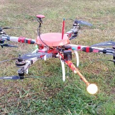
I'm a member of the model aircraft club FMS Spaarnwoude near Amsterdam and I started building and flying drones. I currently own an octocopter with 1 m span and added a camera with gimbal and a live video link to it. But here in the Netherlands the regulations are strict. On the 5.8 GHz band the maximum transmission power is 25 mW. Which is more than enough because you are also not allowed to fly higher than 100 m and your aircraft always has to be in visible range. But because I am flying near the biggest civil airport in the Netherlands, Schiphol Airport, I want to be sure that I am not transmitting more power then allowed. A friend of mine bought an RF power meter from ImmersionRC, but it costs around €190, which I find way too expensive. I told him that I probably could make my own RF Power Meter for about €50. It turned out to be even less.
How does it work
It was actually not that hard to design a RF Power Meter. There are integrated circuits called Log Detectors which translate measured power into a voltage. So it was just a matter of searching the right log detector. I ended up using the AD8317 of Analog Devices. It has a 1 MHz to 10 GHz bandwidth and a 55 dB dynamic range. I used the basic schematics as drawn in the datasheet and also used the PCB layout suggested by the datasheet for my own design.
The only disadvantage of using the AD8317 is that it comes in a CP-8-1 SMD package. Which is quite an unusual package I believe. It is only 3x2 mm and has seven pads underneath the package. Six of them just barely visible and one middle pad which cannot be reached. The middle pad is attached to GND and used as a thermal pad. It is hard to solder this kind of package with an solder iron because only 0.1 mm of the outer pads are exposed on the outside and you need to use a magnifying glass. With a solder iron it will also be difficult to solder the thermal pad because it cannot be reached at all. But I just finished building my own reflow oven out of a €30 toaster and a Zallus controller (which is really good), so I thought it would not be any problem to mount the package on the PCB. It is wasn't a problem at all. And it can also be done using a rework station with hot air gun. No problem at all. Just be sure not to use too much solder paste.
Schematics
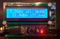
The input comes in at X2, the maximum input is about 0 dBm, so you will have to use an attenuator when the power is more than 1 mW. The absolute maximum is 12 dBm, but all above that will not give a good reading. R1 and R2 form a 52.3 Ω resistance and combined with the internal input impedance of the AD8317 it will give a broadband input impedance of 50 Ω. C1 and C2 are DC blocking capacitors and together with the input impedance they will create a high pass filter with its corner at around 68 kHz. R3 is used for temperature compensation and I chose it to be 500 Ω because it is the recommended value when measuring 5.8 GHz, which I will probably use the most. See the datasheet at page 12 for other values. C3 is there to define the low pass demodulation filter of the output signal Vout. I took the default value of 8p2 because I'm not interested in demodulation. The output signal of the AD8317 is directly connected to the analog input A0 of an Arduino Nano. I chose the Arduino Nano because it is cheap ($4), easy to program and fast enough for our purposes. U1 is an LM4040 2.048 V external voltage reference. The internal reference of the Arduino is not accurate enough. An 2x16 LCD in 4-bit mode is used to display the measured values. Three buttons with pull-down resistors R7, R8, R9 are added to be able to navigate through the menus. R5 is used for adjusting the LCD contrast. R6 is in series with the LCD backlight to limit the current. The PCB does not contain a voltage regulator. The regulator of the Arduino Nano is used to power the other components as well.
PCB Design
I designed the double layer PCB in Eagle. The RF part is layed out as advised by the datasheet. I want to shield the RF part so I made a gap in the silkscreen for that purpuse. But it also works fine without the extra shielding. The rest of the board is quite straight forward. It is possible to make the board smaller by placing the arduino and RF components underneath the LCD. But I like the size as it is now. It is also easier to connect the mini USB to the Arduino when programming it. I've let Seeed Studio make the PCB, it only costs only $14 for 5 PCBs (which is the minimum amount you can order) and I am very pleased with the quality.
Software
The software is quite simple. The main loop of the software first takes 500 samples then it calculates the average power, peak envelope power, minimum power of the last 10 s, maximum power of the last 10 s and the modulation index. It then draws the screen and then it starts taking the next set of 500 samples.
Before reading the calculated values from the display the proper attenuation and frequency must be selected. The selected frequency must be near the frequency of the signal being measured. The selected frequency can be 900 MHz, 1.8 GHz, 2.2 GHz, 3.6 GHz, 5.8 GHz or 8 GHz. The conversion of the measured voltage by the ADC and the actual power in dBm is a linear function with a slope of -22 mV/dB, but the starting point of the function is different for each frequency. The starting points of these frequencies are in the datasheet. It is possible to add other frequencies, but you will have to calibrate them with a power source of which you know the power it outputs for that particular frequency. Since I do not have such a device I am not able to calibrate the device, I took the values from the datasheet. Therefore I did not add a calibration function to the software yet.
The software will also give you a warning when too much power is put into the device and when the amount of power is too low. Too low power will result in a large error according to the datasheet. By pressing the up or down button you can scroll through the measure menus. All power values are in dBm and Watt. You can select the frequency and attenuation by clicking the enter button when in the main screen. Pressing the enter button when in the min or max screens will reset the 10 s history which is used to calculate the min/max power and modulation index.
Attenuators
I started with a cheap 30 dB attenuator from Aliexpress, but I know these are not very accurate. So I do not know the exact attenuation. I also do not know the frequency charcteristics. So I ordered a VAT-20W2+ (20 dB) and VAT-30W2+ (30 dB) attenuator from Mini-Circuits. These come with a datasheet and I added those models with their characteristics to the software. Now it is possible to either select one of those models of set a custom attenuation. When selecting a model, the software will set the attenuation for the selected frequency according to the datasheet provided by the manufacturer of the attenuators.
Case
I've designed a case in DesignSpark Mechanical which can be printed with a 3D printer. These and the stl files have been added to this article.
Bill of materials
Part Value Package Costs (euro)
C1 47nF C0805 0.08
C2 47nF C0805 0.08
C3 8p2F C0603 0.08
C4 100nF C0805 0.08
C5 100pF C0805 0.08
J1 6-20V SPC4078 1.21
PCB1 ARDUINO_NANO 4.00
R1 51Ω R0603 0.02
R2 1.3Ω R0603 0.02
R3 500Ω R0805 0.02
R4 620Ω R0805 0.02
R5 10kΩ LI10 0.02
R6 330Ω R0805 0.02
R7 10kΩ R0805 0.02
R8 10kΩ R0805 0.02
R9 10kΩ R0805 0.02
S1 DOWN B3F-10XX 0.60
S2 ENTER B3F-10XX 0.60
S3 UP B3F-10XX 0.60
U$1 AD8317ACPZ-R7 11.59
U1 LM4040C20IDBZTG4 SOT95 3.19
U2 LCD-16X2 5V 3.95
X2 SMA-142-0701-801/806 8.00
PCB 2.00
30dB attenuator 8.00
Total costs 42.52
UPDATE
Software V1.1
- Added the ability to select a predefined attenuator profile of the Mini-Circuits VAT-20W2+, VAT-30W2+ or a custom attenuation. When selecting one of the two profiles, the correct attenuation is selected for the selected frequency.
- Attenuations now have 0.1 dBm accuracy.
- Attenuation settings now have been moved to a separate menu item.
Schematics / board
- Added a diode for polarity protection
If you have any questions please ask. I'm happy to answer them. You can use and change the software as you like. Maybe you can post a better version on this page or send it to me or add some more features. I was not able to test the modulation value becaus I currently do not have a signal generator which can generate AM signals. Maybe someone else can test it and send me the results. The function may be useless.
Regards,
Joost Breed
Joost Breed
Discussion (24 comments)


Larrt Dodd 3 years ago
Where can I find the documentation to tell me how to use the power meter. The three switches need to know which does what.
Thanks
Thanks
Reply

breedj 3 years ago
You can find a pdf and a flowchard under Other in Project elements at the top of this project.
Here is a direct link:
https://www.elektormagazine.com/files/attachment/32748
Here is a direct link:
https://www.elektormagazine.com/files/attachment/32748
Reply
Show more
1 Comment(s)

Wolfgang Schwarz 5 years ago
Hello BreedJ,
i have a question to the RTadj-resistor value. You use in your setup a 500Ohm resistor. This is usable for about 5Ghz measurements according to the datasheet. But if i want to measure from 2.4 Ghz down to 22 Mhz, do i have to change then the RTadj resistor for the different frequencys i want to measure?
In the menue from the Power Meter i can select the measured frequency range. But the RTadj-resistor is always the same. What is the effect if i measure different frequency ranges without changing the RTadj-resistor value according to the datasheet?
Thanks for your help.
Wolfgang
Reply
breedj 5 years ago
Hi Wolfgang,
The cheap ones I got from Aliexpress, but I do not know if they are any good. The mini-circuit attenuators I'm not sure, but I think I ordered them at the dutchrfshop.nl, but I'm not sure they sell them anymore.
I can only find a Polish site:
https://www.kabeltechnika.pl/produkt/16085/fixed-attenuator-vat30w2-minicircuits.html
Digikay also sells SMA attenuators which are not too expensive. But mini-circuit are the only one which supplies a data sheet with attenuation by frequency graph.
Joost
Reply
Wolfgang Schwarz 5 years ago
Hello Joost,
Thanks for your answer. I guess i go the same way like you and choose the resistor based on my favorite measured frequency.
But i have another question to the attenuators you use. Where did you buy them? I can't find a distributor in Germany who sell them.
Wolfgang
Thanks for your answer. I guess i go the same way like you and choose the resistor based on my favorite measured frequency.
But i have another question to the attenuators you use. Where did you buy them? I can't find a distributor in Germany who sell them.
Wolfgang
Reply
breedj 5 years ago
Hi Wolfgang,
Ideally you would like to change RTadj for every measurement (frequency), but as the datasheet says you will have to experiment with it. Since this is not suitable for a project like this I decided to choose the value from their table based on the frequency I would be measuring at most times. Switching to another resistor value based on the set frequency would be a nice addition to a next version though. I'm not sure what the error will be when the 'wrong' value is used. I assume it will be slightly off, but not much. But you can easily measure that by doing the same measurement with different values.
Joost
Reply
Show more
3 Comment(s)

Nancy Maaty 6 years ago
I am a senior student in electronics and communication field .I needed to order the integreted board which contain the module and IC8317 and microcontroller (Arduino) like the picture shown above i need a board that contain all the piecies to gether integreted on one board
any help for my issue
any help for my issue
Reply
Show more
0 Comment(s)

Sharafath Mihilar 6 years ago
Hello, My Final year indicidual major project is a Real time Power measurement system for RF signals. In this I have planned to use the same system as you have done for a range of 2.4Ghz to 5Ghz. So my doubt is can I use this W1043 Antenna to receive 2.4GHz to 5Ghz frequency and input the same AD8317 and measure the output using your Module.
Reply

breedj 6 years ago
If the measurements are relative to each other than this approach will work. But I do not know if the signals are strong enough. In that case you will need an rf amplifier.
If you are going to measure wifi you also will not need to scan the complete range of 2.4-5GHz. But only around 2.4GHz and 5GHz. I advise to buy two different antenna's. But be aware of the cheap antenna's. Some do not have the correct lenght and are sold for the wrong frequency band. Take them apart and check the antenna length.
If you are going to measure wifi you also will not need to scan the complete range of 2.4-5GHz. But only around 2.4GHz and 5GHz. I advise to buy two different antenna's. But be aware of the cheap antenna's. Some do not have the correct lenght and are sold for the wrong frequency band. Take them apart and check the antenna length.
Reply
Sharafath Mihilar 6 years ago
First of all thank you very much for replying for my comment.
Sure I'll look into it. My plan is to measure power levels only for WIFI signals like measuring the power levels of wifi signal in a room. So as you said I planned to take one wideband antenna.
Thank You
Sure I'll look into it. My plan is to measure power levels only for WIFI signals like measuring the power levels of wifi signal in a room. So as you said I planned to take one wideband antenna.
Thank You
Reply
breedj 6 years ago
It is possible to connect an antenna to the AD8317. But I doubt the kind of antenna you are referring to is capable of receiving the complete range from 2.4GHz to 5GHz. Normally the bandwidth of these antennas are 200MHz or so. You might have to use a different (wide band) antenna or multiple antennas depending on the frequency you are going to measure. Also you need to know the antenna characteristics. It will not be linear.
If signals are weak you might have to use a amplifier as well. Be sure you are in the input range of the AD8317. Not that the amplifier also has his own characteristics you need to know for an accurate reading. Be aware that these antennas are also directional.
If signals are weak you might have to use a amplifier as well. Be sure you are in the input range of the AD8317. Not that the amplifier also has his own characteristics you need to know for an accurate reading. Be aware that these antennas are also directional.
Reply
Show more
5 Comment(s)

Ed van Loo 6 years ago
Just wanted to say this is an awesome project.
I'm going to build a (relative) power meter for my 1.296MHz SSPA (using a directional coupler of course!) with the AD8317.
My only remark to the author is: Attenuator values aren't expressed in dBm but in dB. dBm's are power levels relative to 1mW (0dBm).
I'm going to build a (relative) power meter for my 1.296MHz SSPA (using a directional coupler of course!) with the AD8317.
My only remark to the author is: Attenuator values aren't expressed in dBm but in dB. dBm's are power levels relative to 1mW (0dBm).
Reply
Ed van Loo 6 years ago
Clemens,
Thanks for updating the article. I think now the only part of the text that is a bit strange is this sentence:
"The absolute maximum is 12 dBm, but all above that will not give a good reading."
I think it would be better to say: all above 0dBm will not give a good reading. Anything above 12dBm will possibly destroy the chip.
cheers Ed
Reply

breedj 6 years ago
Hi Ed,
I'm very happy that a lot of people like you like this project. I'm glad I shared it.
I know about the typos I made in the description of this project. But I'm not able to change the text unfortunatly. As you might have seen I've used dB in the comments, project updates and software for attenuation. If you see a typo in the software, please let me know.
Reply
Show more
3 Comment(s)

GEROLAMO LATORRE 6 years ago
Hello. I'm playing with your work and I thank you for sharing it ...
but I'm currently stopped because when I insert a positive voltage value on A0
the value transferred in Watt and dBm on the display decreases
instead of growing so I ask you can you help me?
Where am I wrong?
I use an 8307 for now.

73 IW8PNY
Reply

Leif Eriksson 6 years ago
Hi i trying to compile RF_Power_Meter_V1_4 but don't sucseded ver 1.0 and 1.1 works. I get error RF_Power_Meter_V1_4:769:16: error: variable or field 'bubleSort' declared void
void bubleSort(calibrationPoint data, int size) if i coment out call and the function it compile! i use IDE 1.8.7
Thanks for help!
void bubleSort(calibrationPoint data, int size) if i coment out call and the function it compile! i use IDE 1.8.7
Thanks for help!
Reply
breedj 6 years ago
Hi Gerolamo,
That is because you are using the AD8307 instead of the AD8317.
The output slope of the AD8307 is positive, +35mv/dB, but the one I use in this project has a negative slope of -22mv/dB. So you need to change the software.
If you are using my software you have to change the constants:
MV_DB_SLOPE
and
all the values in DBM_AT_0V
I guess those arrays are all different because the AD8307 will only work up to 500MHz.
Here is the datasheet of the chip you are using:
https://www.analog.com/media/en/technical-documentation/data-sheets/ad8307.pdf
Here is the datasheet of the one I use:
https://www.analog.com/media/en/technical-documentation/data-sheets/AD8317.pdf
Joost
Reply
Show more
6 Comment(s)

arash khajooei 6 years ago
hi
i used your PCB to make a power meter and used a blue light LCD 1602 but the characters show in black not white in LCD screen ! what should I do? I know that in your layout your are not connected vss to gnd ! do you think there is a problem with my power supply?
i used your PCB to make a power meter and used a blue light LCD 1602 but the characters show in black not white in LCD screen ! what should I do? I know that in your layout your are not connected vss to gnd ! do you think there is a problem with my power supply?
Reply

Show more
1 Comment(s)

Hans Venema 6 years ago
Hi Joost,
Is it possible to contact me by email about the rf power meter (2015), i have some serious questions on how to solder the Analog Devices rf-detector hence the lack of proper equipment here.
My email: silicondesign(at)casema(dot)nl
Think you in advance.
Kind regards,
Hans
Is it possible to contact me by email about the rf power meter (2015), i have some serious questions on how to solder the Analog Devices rf-detector hence the lack of proper equipment here.
My email: silicondesign(at)casema(dot)nl
Think you in advance.
Kind regards,
Hans
Reply
Hans Venema 6 years ago
Dear Graham,
You're quite right! All the way, however i've corrected my "mistake" by making the project anyways with some -very much appreciated- help from Joost himself. The point i was trying to make is that some smd- chip, or a kind-of-like smd- chips are so small that it is hadrly impossible for the DIY'-er to solder the in a correct and good way on a pcb board. That's no Joost's fault, it the industry wich demands ever smaller components and in this project was that the Analog Devices rf- detector chip.
As i told Joost already there's no fun buying a "ready made" board, then the fun of building projects is taken out of the hobby, so but don't judge me to hard will you?
Thank you kindly.
Hans.
Reply

Graham Rendell 6 years ago
Hans,
I feel you are being unfair to Joost with your comments. I am very much from the "old school" electronics DIY time when projects were built on Veroboard (strip board) or we would attempt to make our own PCBs. However manufacturers of new and complex chips often no longer offer DIY friendly DIL chip packages especially where RF is concerned. Time was when I had trouble reading IC part numbers on chips, these days I have trouble even seeing the number of pins / pads on some devices. With the ability to buy ready built PCBs on the internet from a Real Time Clock to a GSM cell phone at a price less than the bits cost, I for one am happy to go that way and spend my time on the software and not the soldering. Been there, done that. Joost is obviously a keen DIYer when he says he built a solder reflow system using a toaster and did offer some advice on using solder paste. The fact is for many new chips a PCB is essential, so why not buy it with the chip already mounted and regard the PCB as another component?
I feel you are being unfair to Joost with your comments. I am very much from the "old school" electronics DIY time when projects were built on Veroboard (strip board) or we would attempt to make our own PCBs. However manufacturers of new and complex chips often no longer offer DIY friendly DIL chip packages especially where RF is concerned. Time was when I had trouble reading IC part numbers on chips, these days I have trouble even seeing the number of pins / pads on some devices. With the ability to buy ready built PCBs on the internet from a Real Time Clock to a GSM cell phone at a price less than the bits cost, I for one am happy to go that way and spend my time on the software and not the soldering. Been there, done that. Joost is obviously a keen DIYer when he says he built a solder reflow system using a toaster and did offer some advice on using solder paste. The fact is for many new chips a PCB is essential, so why not buy it with the chip already mounted and regard the PCB as another component?
Reply
Hans Venema 6 years ago
Thank you kindly for your reply and comments, but that was NOT my itention. I thought this was a diy-project (i.e. hobby project), not mounting ready-made units on pre-fabricated boards. If you choose this way to go, you'll be far better off buying some (second-,) hand (calibrated) Hewlett Packard/Boonton rf- powermeter from eBay or wherever/whoever sells them...
My two cents: most people do.
Fact: electronics isn't that popular anymore these days, the number of people wich where once "into" electronics "in a diy- way", reduce (in numbers) every year downwards.
However thank you for presenting this project.
Regards,
Hans Venema
My two cents: most people do.
Fact: electronics isn't that popular anymore these days, the number of people wich where once "into" electronics "in a diy- way", reduce (in numbers) every year downwards.
However thank you for presenting this project.
Regards,
Hans Venema
Reply
Show more
4 Comment(s)


Hedwig 7 years ago
Also see: https://www.elektormagazine.com/labs/rf-power-meter-with-seperate-rf-break-out-board-160193
Reply

Show more
2 Comment(s)

Mansueto Grech 7 years ago
Hi Joost,
Unit assembled an working Fine.
I have a question If I may.
Is it possible to substitute the pre defined power calibration with new Frequencies.
As I would like it to be calibrated on the Ham Bands and mainly 144, 432, 1296 2304 5700Mhz. and possibly 10Ghz.
Thank you in advance
regards
Mans.
Unit assembled an working Fine.
I have a question If I may.
Is it possible to substitute the pre defined power calibration with new Frequencies.
As I would like it to be calibrated on the Ham Bands and mainly 144, 432, 1296 2304 5700Mhz. and possibly 10Ghz.
Thank you in advance
regards
Mans.
Reply
breedj 6 years ago
Hi Barry,
I think you are refering to the elektor branch https://www.elektormagazine.com/magazine/elektor-201803/41378
when talking about R5. R5 in my schematics is a variable resistor.
You can buy 0 Ohm resistors almost everywhere. Just type in 0 Ohm in any web shop like Farnell or Aliexpress. 1% is the accuracy. The minimum power the resistor should be able to dissipate is 62.5mW. You can also use a piece of wire instead of the 0 Ohm resistor if you like. 0 Ohm resistors are normally used as either a selector (like a jumper) or in this case you can change R4 and R5 later if you like. But for now, short R5 and do not solder R4 on the pcb.
The project PDF says about R4 and R5: 'The output signal Vout is fed to the VSET input via the voltage divider R4/R5. For R5 the value shown on the schematic is 0 Ω, while R4 is not mounted (NM).'
VSET can actually be used to change the logarithmic output slope of the AD8317. See the datasheet page 13. If you do then the software should also be changed.
About the .ino files.
You must open both files in the Arduino IDE. RF_Power_Meter_v1_4.ino uses Menus.ino.
Because both have the .ino extension they will be concatinated to one file when the project is compiled. It is just a lazy way to seperate the menu code from the other code. For the project to compile you must create a folder with the name 'RF_Power_Meter_v1_4' and put both the Menus.ino and RF_Power_Meter_v1_4.ino in there. Both files should be opened in the IDE. See the attachment. Be sure to install the libraries EEPROM, Bounce2 and LiquidCrystal as well using the Library Manager of the Arduino IDE.
Reply
breedj 7 years ago
Hi Mans,
Unfortunatly I do not own equipment with frequencies higher than 1GHz. I posted new firmware which contains the possibility to do your own callibration when you have the equipment for it.
Maybe someone else reading this and owning the equipment can help us out.
joost
Unfortunatly I do not own equipment with frequencies higher than 1GHz. I posted new firmware which contains the possibility to do your own callibration when you have the equipment for it.
Maybe someone else reading this and owning the equipment can help us out.
joost
Reply
Show more
4 Comment(s)

foad moradi 7 years ago
hi there . do you use a directional coupler to send the rf signal to your board or not ? is it possible for ad8317 to receive input without directional coupler? i saw no mention about it or usage of coupler in your explinations .
regards
regards
Reply
breedj 7 years ago
Hi,
I do not use any directional couplers in the project. The AD8317 can be used without directional couplers. Just be sure that the signal does not contain more power than +10dBm. If it does then you should use a suitable attenuator. The best range is between -45dBm and -10dBm. So for a 1W (30dBm) transmitter you should use an attenuator of 40dB or more. The attenuator should also be cabable of dissipating that amount of power. So in this case the attenator should be 1W or more.
Joost
Reply
Show more
1 Comment(s)

Jose G Vicente 7 years ago
Thank you for this article and all the details. I have a question, do you have example on how you use the device. Are you conecting the antenna output of your transmitter to the input of the power meter ? or can you connect an antena as the input for the RF power meter, then putting it in close proximity with the transmitter?
Thanks in advance !
Thanks in advance !
Reply
breedj 7 years ago
Hi Jose,
You can do both. You can connect an antenna to test and compare antennas. To actually meaure the output power of your transmitter you can connect the RF meter to the transmitter. But if you are connecting it directly to the transmitter you will need an attenuator between the meter and the transmitter. The maximum input of the RF meter is +10dBm. But for a good reading the inout power of the meter should be between -45dBm and -10dBm. More than +10dBm (10mW) will damage the RF meter permanently.
For instance for 50 Ohm impedance: If you have a 10W transmitter (40dBm) you will need an attenuator between 50dB to 85dB to get a good reading. You can set the attenuation in the meter so it will calculate the correct output power of your transmitter for you.
For signals below 1mW you will not need an attenuator.
I'm changing the software a bit. I will create a manual after I've finished with that.
Joost
Reply
Show more
1 Comment(s)


CHARLES FERREIRA 8 years ago
BONJOUR
j,ai une erreur de compilation
message d,erreur suivant
erreur de compilation pour la carte arduino nano
que faire
cordialement Charles
j,ai une erreur de compilation
message d,erreur suivant
erreur de compilation pour la carte arduino nano
que faire
cordialement Charles
Reply
breedj 8 years ago
At the bottom it says 'No such file or directory #include <Bounce2.h>'. So you need to install the libraries which are included (Bounce2, EEPROM, LiquidCrystal). See image.
You can also copy the libraries from RF_Power_Meter_V1_1.zip and copy those to your arduino library folder (C:\Program Files (x86)\Arduino\libraries)
Some people has problem with the header file EEPROMAnything.h, so I have changed the structure a bit. I merged the EEPROMAnything.h code with the main code. So please download the latest rf-power-meter-v1-1.zip. EEPROMAnything.h should not be a separate file anymore, it should be removed if it is still in the directory.
Reply
CHARLES FERREIRA 8 years ago
voila les tests
Arduino : 1.8.1 (Windows 10), Carte : "Arduino Nano, ATmega328"
C:\Program Files (x86)\Arduino\arduino-builder -dump-prefs -logger=machine -hardware C:\Program Files (x86)\Arduino\hardware -tools C:\Program Files (x86)\Arduino\tools-builder -tools C:\Program Files (x86)\Arduino\hardware\tools\avr -built-in-libraries C:\Program Files (x86)\Arduino\libraries -libraries C:\Users\Charles F\Documents\Arduino\libraries -fqbn=arduino:avr:nano:cpu=atmega328 -ide-version=10801 -build-path C:\Users\CHARLE~1\AppData\Local\Temp\arduino_build_393332 -warnings=none -prefs=build.warn_data_percentage=75 -prefs=runtime.tools.avr-gcc.path=C:\Program Files (x86)\Arduino\hardware\tools\avr -prefs=runtime.tools.avrdude.path=C:\Program Files (x86)\Arduino\hardware\tools\avr -prefs=runtime.tools.arduinoOTA.path=C:\Program Files (x86)\Arduino\hardware\tools\avr -verbose C:\Users\Charles F\Downloads\rf power elector\RF_Power_Meter_V1_1\RF_Power_Meter_V1_1.ino
C:\Program Files (x86)\Arduino\arduino-builder -compile -logger=machine -hardware C:\Program Files (x86)\Arduino\hardware -tools C:\Program Files (x86)\Arduino\tools-builder -tools C:\Program Files (x86)\Arduino\hardware\tools\avr -built-in-libraries C:\Program Files (x86)\Arduino\libraries -libraries C:\Users\Charles F\Documents\Arduino\libraries -fqbn=arduino:avr:nano:cpu=atmega328 -ide-version=10801 -build-path C:\Users\CHARLE~1\AppData\Local\Temp\arduino_build_393332 -warnings=none -prefs=build.warn_data_percentage=75 -prefs=runtime.tools.avr-gcc.path=C:\Program Files (x86)\Arduino\hardware\tools\avr -prefs=runtime.tools.avrdude.path=C:\Program Files (x86)\Arduino\hardware\tools\avr -prefs=runtime.tools.arduinoOTA.path=C:\Program Files (x86)\Arduino\hardware\tools\avr -verbose C:\Users\Charles F\Downloads\rf power elector\RF_Power_Meter_V1_1\RF_Power_Meter_V1_1.ino
Using board 'nano' from platform in folder: C:\Program Files (x86)\Arduino\hardware\arduino\avr
Using core 'arduino' from platform in folder: C:\Program Files (x86)\Arduino\hardware\arduino\avr
Detecting libraries used...
"C:\Program Files (x86)\Arduino\hardware\tools\avr/bin/avr-g++" -c -g -Os -w -std=gnu++11 -fpermissive -fno-exceptions -ffunction-sections -fdata-sections -fno-threadsafe-statics -flto -w -x c++ -E -CC -mmcu=atmega328p -DF_CPU=16000000L -DARDUINO=10801 -DARDUINO_AVR_NANO -DARDUINO_ARCH_AVR "-IC:\Program Files (x86)\Arduino\hardware\arduino\avr\cores\arduino" "-IC:\Program Files (x86)\Arduino\hardware\arduino\avr\variants\eightanaloginputs" "C:\Users\CHARLE~1\AppData\Local\Temp\arduino_build_393332\sketch\RF_Power_Meter_V1_1.ino.cpp" -o "nul"
"C:\Program Files (x86)\Arduino\hardware\tools\avr/bin/avr-g++" -c -g -Os -w -std=gnu++11 -fpermissive -fno-exceptions -ffunction-sections -fdata-sections -fno-threadsafe-statics -flto -w -x c++ -E -CC -mmcu=atmega328p -DF_CPU=16000000L -DARDUINO=10801 -DARDUINO_AVR_NANO -DARDUINO_ARCH_AVR "-IC:\Program Files (x86)\Arduino\hardware\arduino\avr\cores\arduino" "-IC:\Program Files (x86)\Arduino\hardware\arduino\avr\variants\eightanaloginputs" "-IC:\Program Files (x86)\Arduino\hardware\arduino\avr\libraries\EEPROM\src" "C:\Users\CHARLE~1\AppData\Local\Temp\arduino_build_393332\sketch\RF_Power_Meter_V1_1.ino.cpp" -o "nul"
"C:\Program Files (x86)\Arduino\hardware\tools\avr/bin/avr-g++" -c -g -Os -w -std=gnu++11 -fpermissive -fno-exceptions -ffunction-sections -fdata-sections -fno-threadsafe-statics -flto -w -x c++ -E -CC -mmcu=atmega328p -DF_CPU=16000000L -DARDUINO=10801 -DARDUINO_AVR_NANO -DARDUINO_ARCH_AVR "-IC:\Program Files (x86)\Arduino\hardware\arduino\avr\cores\arduino" "-IC:\Program Files (x86)\Arduino\hardware\arduino\avr\variants\eightanaloginputs" "-IC:\Program Files (x86)\Arduino\hardware\arduino\avr\libraries\EEPROM\src" "C:\Users\CHARLE~1\AppData\Local\Temp\arduino_build_393332\sketch\RF_Power_Meter_V1_1.ino.cpp" -o "C:\Users\CHARLE~1\AppData\Local\Temp\arduino_build_393332\preproc\ctags_target_for_gcc_minus_e.cpp"
C:\Users\Charles F\Downloads\rf power elector\RF_Power_Meter_V1_1\RF_Power_Meter_V1_1.ino:12:21: fatal error: Bounce2.h: No such file or directory
#include <Bounce2.h>
^
compilation terminated.
Utilisation de la bibliothèque EEPROM version 2.0 dans le dossier: C:\Program Files (x86)\Arduino\hardware\arduino\avr\libraries\EEPROM
exit status 1
Erreur de compilation pour la carte Arduino Nano
cordialement Charles F
Reply
Show more
5 Comment(s)

Kadir Mr Haldenbilen 8 years ago
I plan to use such a decetor for local positioning. If I use say three different 5.8 GHZ source (like XYC-WB-DC) and a detector like this one, I am hoping to get my position relative to the sources. Will that be possible? Signal strength might be calibrated as distance from a source, so I obtain three distace values and calculate my (detecetor's) position.
Reply
breedj 8 years ago
I'm not an expert on this , but I do not think measuring power is a suitable way to measure distance. Its is not accurate enough. Distance and power are not lineair, power will be very low very quickly. How do you know which transmitter you receive? You have to point directional antenna's exactlu to the transmitters. Normally you would use radar technology for this. You then need to look at subject like doppler, convolution, matched filters, pulse compression, etc.
Reply
Show more
1 Comment(s)

dave l crogan 8 years ago
Hello,
Are there any solutions to get this to reconize up to 18ghz?
Are there any solutions to get this to reconize up to 18ghz?
Reply

F1CHF 8 years ago
hello
AD8317 datasheet says 10 ghz and I didn't find a
better one on AD familly.
One suggestion :
on the AD8317 PCB corner, add a 4 wire connector
to be able to CUT this sensor and put in a remote
box ... I will allow to mesure very near of the DUT
a simple 4 wires cable between the "remote box"
and the main board is suffisant.
So two options are possible , sensor on the main board or install sensor board in a "remote box"
my two cents ...
Francois F1CHF
Reply
Show more
2 Comment(s)

CopterCarl 8 years ago
Hello Joost,
It is a very nice idea for checking the FPV- or camera transmitter equipment.
As can easily be seen, I like flying Multicopters too.
I also use a 25mW (max. allowed) transmitter on 5.8 GHz.
I think the 100m limit will be a law in the future here in Germany too.
But I think (hope) for model aircraft clubs will be an exemption.
I think about 300m altitude.
By the way, my biggest Copter is an X8 (NAZA M V2) about 70cm “wingspan” and two smaller Quadrocopter (KK2.1).
Measurements in the frequency range of 5.8 GHz are very difficult for me and I have no experience. Nice to see you can make it and you can solder such thinks like an AD8317 “out of a 30 euro toaster”.
Congratulations!
Greetings from South West Germany on a cold, wet day
“Holm- und Rippenbruch”
Carl
Reply

breedj 8 years ago
Carl,
Thank you for the compliments. Fortunatly there is only one smd component on the board. So you can solder it by hand as well. But the smd oven is very convenient.
We will see where it ends with the restrictions. A lot of ignorant people are the cause of more regulations because they are flying near people and buildings. My club is near Schiphol airport, so there are special regulations there as well.
Joost
Reply
Show more
4 Comment(s)

ervin brucal 8 years ago
Very nice project.
I think if we could tweak it to be able to use for 433mhz, 915mhz and 2.4ghz it will be superb.
adjustment in R tadj and software modification.
Some more if we could add the SWR meter functionality will be great also.
im only having difficulty with the slope for the performance characteristics, im not sure how can i implement it through arduino.
Reply
breedj 6 years ago
The ad8318 can only handle up to +12dBm. It will be damaged when the input is higher. But the characteristics are only lineair up to -5dBm. So you will always want have a lower input power then -5dB. If the device you want to measure supplies more than -5dBm, then you will have to use an attenuator.
When using an attenuator you can just add the attenuation value int dBm to the value measured (dBm) by the ad8318.
So if you use a 20dBm attenuator and the ad8318 measures -8dBm then the output power of the device you are measuring is actually +12dBm. The attenuator will absorbe the 20dBm and turn it into heat. Therefore be sure to use an attenuator which can handle the power. 20dBm attenuation at 1W is much more than 20dBm attenuation at 10mW.
Be sure to understand the concept of dB and dBm, dBV, dBA, etc.
dB is the ratio between two values in a logarithmic scale. dBm is the ratio of a value compared to 1mW in a logarithmic scale. Because the ratios are in a logarithmic scale you can add or subtract them.
So if dBm means decibel compared to 1m. Then 0dBm = 1mW, +10dBm = 10mW, +15dBm = 0.032mW. Power in dBm less than 0 are smaller than 1mW. So -10dBm is 0.1mW = 100uW and -23dBm is 5uW.
Here is a link to a dBm to Watt calculator:
https://www.rapidtables.com/convert/power/dBm_to_Watt.html
Also be sure to use 50 Ohm coaxial cables and 50Ohm attenuators to get correct values.
I hope this helps.
Reply
ervin brucal 6 years ago
not sure if my understanding for the final (+)dbm which is the true power input to the ad8318 is correct, so based from the slope formula we can compute for the (-)dbm then with the attenuator[(+)dbm] we just need to add the (-dbm) plus the attenuator value in order for us to get (+)dbm which is the final power input to the module.haha i got confused to your explanation last time regarding for the (-)dbm which can attain from slope formula, yours is in positive which i thought will be the final input power to module hehe
Reply
breedj 6 years ago
Hi Ervin,
I think that's your only option. Just use the typical value. The datasheet shows the min and max for 900MHz and 1900MHz. It does not tell the accuracy, what percentage of IC samples where near the typical value. So I cannot really tell how accurate it will be, but my ic's where mostly around 0.5 dBm different than the typical value in the datasheet. Which is quite good I think.
Joost
Reply
breedj 7 years ago
The slope is 22.33mV per dB (22mV according to the datasheet). If you measure 0,75V when connecting -20dBm input power then DBM_at_0V for that frequency will be:
dBm_at_0V = 'Known input power' + ('measured voltage' / slope)
-20dBm + (0,75V / 0.02233V) = 13.59 dBm
Be sure to do measurements in the linear region (between -10dBm and -45dBm)
dBm_at_0V = 'Known input power' + ('measured voltage' / slope)
-20dBm + (0,75V / 0.02233V) = 13.59 dBm
Be sure to do measurements in the linear region (between -10dBm and -45dBm)
Reply
breedj 7 years ago
Yes. When working wit dB you can just add or subtract the values. So when you connect a transmitter with +10dBm power to a 30dB attenuator the output will be +10dBm - 30dB = -20dBm. The log detector will only see the -20dBm, it is not aware of the attenator. The attenuator absorbes 30dB and converts it into heat.
You can see in the datasheet of the AD8317 what the output voltage of the detector will be. If you are measuring a 900MHz signal the voltage will be about 0.8V.
When using a 40dB attenuator the input power of the log detector will be +10dBm - 40dB = -30dBm. Then the output voltage will be about 1V according to the datasheet (top left chart on page 7).
As you can see in the graph the power to output voltage ration is linear between -50dBm and -10dBm. The other curves in the graph show the error of the measurement. As you can see the log detector is only usable when measuring power between -50dBm and -10dBm. For other values the error is too large. it also changes by temperature. This is another reason why you have to use an attenuator. Not only to protect your log detector but also to prevent large error in your measurement. The detector can measure a +5dBm signal without being destroyed, but the error will be more than 4dB, which is a lot. Remember that 3dB is twice as much power. 6dBm is twice as much power than 3dBm (resp. 4mW and 2mW)
Joost
Reply
ervin brucal 7 years ago
Sorry im just noob with this rf thing, i just want to learn first the principle of it.
let us say i'll be going to test the 30db and 40db attenuators, output voltage will be different for the 2 attenuators right, no arduino attach just the basic components only for the log detector.
thanks.
let us say i'll be going to test the 30db and 40db attenuators, output voltage will be different for the 2 attenuators right, no arduino attach just the basic components only for the log detector.
thanks.
Reply
breedj 7 years ago
Hi Ervin,
There is a menu option where you can specify the attenuation you use. If you have a +10dBm signal and a 30dB attenuator then the meter will measure a voltage which will result in a -20dBm measurement. But because you specified that the attenuation is 30dB then it will display +10dBm. So you will not have to calculate it yourself for each measurement. Ofcoarse you will need to know the exact attenuation.
Is that what you want to know? Or do you mean something else?
Joost
Reply
breedj 8 years ago
Ervin,
I just bought a Marconi 2022E 1.01GHz AM/FM signal generator. So I will be able to do some measurements at 433MHz and 900MHz and maybe some other frequencies as well. I will put those ranges in the software. I can also test the AM modulation measurement. The accuracy of the generator should be around 1dB and 4% for the modulation depth.
Joost
Reply
breedj 8 years ago
Hi Ervin,
I've had a look at the SWR meter. As I understand you will need power meters, one for both directions. And a directional coupler.
I am not a radio amateur so I do not need an SWR meter myself. I am also not able to do the measurements needed to check if it really works.
Regarding the question about the slope. Do you mean you do not understand how I implemended it in the software?
Best regards,
Joost
Reply
breedj 8 years ago
Hi Ervin,
Thank you for the compliment.
If you want to use it for 915MHz, just select the nearest, 900MHz, in the menu. The same with the other frequencies. So 2,2GHz for 2.4GHz measurement. Unfortunatly I do not have the equipment to add other frequencies than specified in the datasheet. Maybe someone else can. So to measure for 433MHz you have to select 900MHz at this moment.
I will have a look at the SWR meter functionality. It will require some additional hardware. I'm also not sure I can test that functionality. I'm not a radio amateur. I do not have a GHz frequency generator or a spectrum analyser.
Maybe someone else reading this can help out.
Implementing extra characteristics will not be a problem with arduino though.
Best regards,
Joost
Reply
Show more
19 Comment(s)

funkhaus 8 years ago
Hello, a nice project. Can I buy the PCB with you?
Best regards
Andreas
Best regards
Andreas
Reply
breedj 7 years ago
The bad news: I'm currently out of kits. I also removed the project update about the kits a few months ago because people kept asking me about it. I'm not planning to make new kits.
The good news: Elektor has made a fork of this project which uses my firmware.
https://www.elektormagazine.com/labs/rf-power-meter-with-seperate-rf-break-out-board-160193
I think there will be an article in the magazine soon. The project consists of two boards. The RF stuff has been made on a 4 layer board for better performance.
The RF board can already be ordered in the shop:
https://www.elektor.com/search?cat=0&q=160193
Reply
breedj 8 years ago
You are not the only one asking. So I ordered a batch of 10 last week. Please drop me an email and I will contact you when thay arrived.
joost.breed.quicknet@gmail.com
joost.breed.quicknet@gmail.com
Reply

Show more
7 Comment(s)
Updates from the author
breedj 7 years ago
Changes:
See the manual for more details about the calibration.
Bastelfix 7 years ago
I build the unit and it works.
But i have a problem with the linearity.
For example:
i used a calibratet RF Power Source for calibration.
-calibration at 140MHz and RF Level-20dBm
-calibration saved
now the following measurement when changing RF Level at the input (all without attenuator) :
RF Level at Input: Display Power Meter:
0 dBm -11,0 dBm
-5 dBm -13 dBm
-10 dBm -15 dBm
-20 dBm -20 dbm (calibration point)
-30 dBm -24 dBm
-40 dbm -28 dBm
-50 dBm -32 dBm
What could be the problem?
Is there a conversion factor not correct?
Best regards, Sven
breedj 7 years ago
Here are some things I can think of which might solve your problem.
I hope this will help.
Best regards,
Joost
Bastelfix 7 years ago
I found the problem.
The reference voltage was not ok. I reworked the PCB File to have a 50 Ohm stripline at the input and via shielding arround the stripline. I tuned the PCB for quick manufacturing on a pcb milling machine.
Now the circuit works really fine! At the end of the band @10GHz you can see a nonlinearity but these are influenced by the components you used. The FR4 material is not really good at these frequencies. i would also like to exchange the 47nF capacitors in the input circuit for other 0402 / 0603 high frequency types.
otherwise it works very well and is very accurate!
best regards, Sven
20180122-140016.jpg (198kb)
20180122-140026.jpg (124kb)
20180122-140430.jpg (197kb)
20180122-140438.jpg (130kb)
20180122-140449.jpg (225kb)
breedj 7 years ago
I'm glad it worked out well. Thank you for sharing your measurements.
You are correct about the fr4 board and the caps. Do you have any specific type or brand of capacitors in mind? Also using a 4 layer board will improve the measurements. But it will increase the costs a lot.
Regards,
Joost
Gregg Winkler 7 years ago
Amazing work indeed and an affordable alternative to ready to purchase items as the Immersion RF Meter.
For occasional users who may not have the time to put together the whole unit /wish I had/, is there also a possibility to simply take an analouge Voltage reading of the AD8318 RF unit and calculate the db/mW values?
Thanks
breedj 7 years ago
That is possible. But you will need the calibration value for the frequency you are measuring. You can use the graphs on page 8 of the datasheet to lookup the power values in dB. Then calculate the power in mW from that.
Datasheet of the AD8318:
http://www.analog.com/media/en/technical-documentation/data-sheets/AD8318.pdf
But only a few graphs are plotted there. You can select the graph which is closest to the frequency you are trying to measure, but it will not be very accurate. It might be off by a few dB, which can be a lot since +/- 3dB is already double or halve the actual value.
My advise for those with less time is to buy the boards from the Elektor shop:
https://www.elektor.com/rf-power-meter-rf-front-end-board-module
https://www.elektor.com/rf-power-meter-mother-board-bare-pcb-160193-2
then they will only need to solder about 15 components or so. The difficult components are already soldered on the rf-board.
Joost
Werner Ehrhardt 6 years ago
I have problems compiling Arduino files.
There are all necessary files and libraries mit.h in the directory and are displayed when opening the Arduino.ide also.
Compiler aborts with the message:
fatal error: Bounce2.h: No searchfile or directory
#include <bounce2.h>
compilation terminated.
The command include <Bounce2.h> appears in the file: RF_Power_Meter_V1_4 in black
The other two include commands appear in red text
What does that mean and how can I be helped?
Kind regards
Werner
breedj 6 years ago
You should have to tabs opened in the IDE. RF_Power_Meter_V1_4.ino and Menus.ino. Those files must be in a folder called RF_Power_Meter_V1_4.
Please first try to download the libraries with the arduino IDE. Go to 'Sketch' --> 'Include library' --> 'Manage libraries...' and lookup and install the libraries:
EEPROM V1.0 by Ivan Grokhotkov
Bounce2 by Thomas O Fredericks
LiquidCrystal by Adafruit
Then try to compile again. Please let me know if that worked.
Beshoy Danial 5 years ago
I want to ask what is not already not soldered So I am going to buy it?
thanks for the great effort u made in this project.
Mansueto Grech 8 years ago
I am interested in a kit.
regards
Mans
Keith Bainbridge 7 years ago
breedj 7 years ago
Mansueto Grech 7 years ago
Will yo be contacting us on the forun or off forum for payment details?
Regards
Mans
breedj 7 years ago
I will send you an email when I have all the components. Most of them are from China. So it will take a few weeks.
regards, Joost
Mansueto Grech 7 years ago
tHANKS FOR INFO
regards Mans
Abirami Anbalagan 5 years ago
Is it possible to get the kit? or if not please may i know where i can get the 10k ohm reisistance with LI10 package as im not able to find the component in my country. please do let me know if the kit can be purchased.
Thanks in advance.
breedj 8 years ago
https://create.arduino.cc/editor/breedj/e9287a73-b31b-49e6-aef5-4fb91888a53c/preview
Werner Ehrhardt 6 years ago
Have all libraries installed.
The bounce2 library appears but contributed.
Compile breaks off with the same error
Kind regards
Werner
breedj 6 years ago
In my case it is one of the next two folders:
C:\Program Files (x86)\Arduino\libraries
C:\Users\Joost\Documents\Arduino\libraries
Also remove all subfolders from the project folder. So only two ino files are left.
Otherwise please enable 'Show verbose output during compilation' in the Tools-->Preferences menu and send me the output to joost.breed.quicknet@gmail.com
Joost
Abirami Anbalagan 5 years ago
TonGiesberts 5 years ago
https://www.elektormagazine.com/labs/rf-power-meter-with-seperate-rf-break-out-board-160193
Look for the Arduino Sketch under Software.
yong 5 years ago
breedj 5 years ago
You can use the power meter to test antennas ofcoarse. But then you test and compare the antennas you would like to use with your receiver of transmitter.
yong 5 years ago
breedj 5 years ago
You might want to check the reference voltage.
How do you know you are 20dB off? What are you actually trying to measure. What is your test setup?
yong 5 years ago
meter with the IC AD8317 .i would like to know the price of the project and if there is a similar project with upgraded features
yong 5 years ago
breedj 5 years ago
http://www.rc-cam.com/forum/index.php?/topic/4139-diy-rf-power-vswr-meter-low-cost/