Simple RS232 - Sequence Sender

A simple RS232 sender for initializing a device with RS232-control-interface - here e.g. a "TGR1_040" RF-signal generator.
Some time ago a 19" rack with a FM sound transmitter "died" in our old broadband cable system. A repair of the circuit from the 1980s was impossible, but a quick replacement was absolutely necessary. In the end, a RF-signal generator "TGR1_040" was used as a temporary solution, where such solutions very often have a very long lifetime :-). This generator saves all its settings and starts with these settings after switching on.
However, the RF output must be activated manually with a pushbutton after switching on or after a power failure.
This was an absolute exclusion criterion in the application environment and demanded an automation solution!
The RF-transmitter has an RS232 interface via which the output can also be activated.
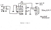
A small circuit has therefore been developed which sends a command sequence terminated with CR and LF to the RS232 RX-DATA input of the transmitter after the power is switched on and then every 60 seconds, which then activates the output.
As a simple and cheap controller the BASIC programmable PicAxe 08M2+ is used.
The PicAxe only provides a serial 0-5V signal, but this is safe enough to control the interface. Thus an RS232 level converter could be omitted.
The BASIC program is largely self-explanatory.
15 seconds after switching on, the sequence is sent for the first time and then repeated endlessly each 60 seconds. For function control a 3mm LED is made to flash.
The BASIC-script and the sequence can be changed or extended very easily if another RS232 device is to be controlled.
The circuit was placed on a small board in the slightly larger housing of a 9-pin SUB-D plug, which could be screwed to the socket on the back of the device.
The RS232 transmitter is powered by a small 5V/500mA power supply, which is connected to the same circuit as the transmitter. Thus it detects possible power failures and also has a deliberately short holding time of less than 5 seconds after the power is switched off.
This is the BASIC-code for the PicAxe08M2+ :
' Automatic RF-ON for TGR1040 RF-Transmitter
' ###########################################
' with PicAxe08M2+
' DB9JG, Peter.Neufeld@GMX.de

' Sends a Command-sequenz "RFON"+CR+LF with (9600,8,N,1) on serTX-Pin
' to surely turn on the RF-Output of the TGR1040 signal generator.
' Sequence starts 15 s after power ON
' and then repeates once per minute
' ATTENTION: Hardware serial out is normally set to  4800,8,N,1
' Thus the change in clock rate to 8M to get (9600,8,N,1).
' LED at  Pin 1 blinks to show the running circuit.
symbol LED = 1
symbol I = b1
symbol K = b2

' ***** main loop *****
main:
	high LED
	for k = 1 to 60
		high LED
		pause 50
		low LED
		if k = 15 then
			high LED
			gosub sender
			wait 2
			low LED
		end if
		wait 1
	next k
'loop back to start
	goto main
' **********************
sender:
	setfreq m8
	sertxd ("RFON", 13,10)
	setfreq mdefault
	return


Discussion (0 comments)