

Recorder-like Electronic Musical Instrument (EWI) and MIDI Controller
The "REMI" is an electronic wind instrument (EWI) with recorder-like fingering scheme. The design has evolved over the last few years and is now in its 3rd major revision.
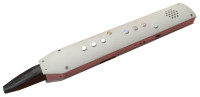
REMI 3 - 'All-in-One' EWI
"REMI 3" is fully self-contained, battery-powered with built-in sound synthesizer, audio amplifier and speaker. It also has a 3.5mm headphone socket for private practice and a 1/4 inch phone jack for audio output to an instrument amplifier. A micro USB connector allows the REMI 3 to be used as a MIDI controller with a virtual synthesizer app on your computer or mobile device.
At the time of writing (Feb-2022), REMI model 3 is in the final stages of development. The prototype design is presented here for DIY electronics hobbyists who are capable of making their own. A printed circuit board and custom enclosure may be produced later to make construction easier.
Preliminary design notes are posted already on the author's website (link below). A complete article with detailed construction notes may be published if there is enough positive feedback from followers.
REMI 3 is based on the "Teensy 3.2" micro-controller module (from PJRC and Sparkfun). Software is developed in the Arduino IDE with "Teensyduino" code library.
The parts to build a REMI should cost much less than a commercial EWI.
REMI source code is freely available (for non-commercial purposes) allowing makers to tailor the firmware to suit their own design variants. (Latest firmware revisions are available on GitHub.)
REMI 2 - EWI MIDI Controller
For makers preferring a simpler wind instrument that is easier to build, the "REMI mk2 handset" design is also presented here. REMI 2 is a MIDI wind controller with classic MIDI OUT connection ( 5-pin DIN socket). This model has no built-in synthesizer, but you can use it to play any MIDI synth or sound module, or connect to a computer via a low-cost USB-MIDI adapter.
Of course you could also build the companion ""REMI synth module" based on a PIC32MX MCU.
(See links further on.)
_______________________________________________________________
Original post (edited) -- relates to earlier REMI versions
The concept for the "REMI" came from a desire to create a simple but practical musical instrument which is easy to learn to play. An early design decision was to model the REMI loosely after existing “electronic wind instruments” (EWI's) using touch-sensitive pads for the “keys” to select the pitch of notes. A breath pressure sensor allows notes to be articulated by blowing into a mouth-piece.
Another major design decision was that the REMI need not emulate precisely the fingering scheme of a traditional wind instrument such as the saxophone, clarinet, flute or recorder (although a few minor design changes would make this possible). These instruments have complicated fingering schemes, of necessity, due to the physical properties of air columns made to produce sound. In contrast, electronic sound-generating devices are not constrained by such physical properties. Hence, a simplified fingering scheme based on the recorder was devised for the REMI. (See fingering charts.)
The instrument may consist of two main parts: a "handset" incorporating the touch-pads and other playing sensors and controls, plus a "controller module" housing a micro-processor, MIDI and audio circuitry and user interface components (LCD screen and keypad).
A push-button switch operated in conjunction with the touch-pads, selects one of several instrument "presets". The presets are chosen from a larger number of available instrument patches built into the micro-controller firmware. The "presets" also select one of a group of MIDI "programs" (instruments) for use with an external MIDI sound module.
Another design objective was that the synth module should be capable of generating a variety of instrument sounds, so that the REMI can be used "stand-alone", i.e. without needing to be plugged into an external MIDI synthesizer or computer. Further, a socket should be provided for direct audio output to an amplifier or headphones.
The remaining original text has been deleted because it is now largely obsolete. Please refer to updates by the author (below).
___________________________________________________________________________
Links
Introduction to the REMI project
Build the REMI mk2 (EWI MIDI controller)
Build the REMI Synth (MIDI Sound Module)
REMI 3 Prototype Design Notes
Discussion (5 comments)

imperte 8 years ago
you can also see my project on this link:
http://www.traussnigg.com/hpt/filius_midi_syntonum/filius_1.html
http://www.traussnigg.com/hpt/filius_midi_syntonum/filius_1.html
Reply

M J Bauer 8 years ago
Thanks, Filius, for the link to your project, which I have now viewed. Do you have any more information on the project? In particular, what fingering style does your handset use? (It looks like it might emulate a classical instrument.) Have you considered replacing the tact switches with touch-pads, now that the MPR121 I2C touch sensor is available?
Reply
Show more
1 Comment(s)

M J Bauer 8 years ago
I'm very interested to get readers' opinions on EWI fingering schemes. Would you prefer the minimalist "binary" fingering scheme proposed for the generic REMI, or one of the fingerings used in traditional wind instruments (flute, sax, recorder, clarinet, oboe, piccolo, etc). They're all different, and many musicians play more than one type of instrument, so it seems to me why not introduce yet another fingering for a new instrument? (The REMI's fingering scheme uses fewer keys, covers a greater pitch range, i.e. 7 octaves, and allows the "touch trigger mode" to operate.)
Reply

ClemensValens 8 years ago
I found the old (1978) magazine again and scanned two pages. According to the text the author played the flute and it took him one and a half year to master playing this keyboard. "It is as difficult as learning to play the recorder." I have never tried it, I just used a piano keyboard.
Reply

El-T 8 years ago
EWI fingering schemes are O.K and useful.
As a 'real' saxophone player it is an advantage to have the possibility to change to this saxophone scheme. Saxophone players usually also play the clarinet, which is again different from the saxophone fingering...but they are able to play them both so it doen't matter!
As a 'real' saxophone player it is an advantage to have the possibility to change to this saxophone scheme. Saxophone players usually also play the clarinet, which is again different from the saxophone fingering...but they are able to play them both so it doen't matter!
Reply
ClemensValens 8 years ago
The first analog synthesizer I built was a design intended for wind instrument players. (The designer also proposed a normal keyboard, which was what I used.) I can look it up because I think I still have the article (from 1978 or so). Attached is a sketch I made from memory, I must check the details. Such a keyboard can be adapted to most playing styles, I guess. With modern capacitive touch technology this can probably be done better. There is only one hand, because the other was used for fiddling with the synthesizer (performance) controls.
Reply
Show more
4 Comment(s)
El-T 8 years ago
Here is some useful information about wind controller lovers...
http://www.patchmanmusic.com/NyleSteinerHomepage.html
http://www.patchmanmusic.com/NyleSteinerHomepage.html
Reply

Johan Berglund 8 years ago
I know that came out a bit harsh, sorry about that.. kind of just threw my thoughts out there. Actually, the handset is probably my favourite part. It looks very sensible to me. Also cleverly made.
I just got hung up on the idea that binary would be better. Like.. instead of having the limitations of the acoustic properties of "real" instruments dictating the way fingerings have to be done, choosing a pattern that in musical logic would seem arbitrary or random just did not strike me as a step up. That's just my opinion, I know.
While I haven't pondered the options for the chromatic notes, other than maybe choose the fingering from valve instruments, I did think a bit about how the octave selection could be done changing only one finger per octave step and having the 0 or base octave intuitively found. This is what I came up with:
(* o * – octave -3)
* o o – octave -2
* * o – octave -1
* * * – octave 0
o * * – octave +1
o o * – octave +2
o o o – octave +3
(o * o – octave +4)
Where "o" is not pressed and "*" is pressed.
Thoughts on that? I know it would ruin the "note off" thing for you, though.
I'd say recorder fingering is somewhat intuitive imho. At least in the first octave and with German fingering. But it sure gets messy in the second octave. There, the possible simplifications in an electronic wind instrument are truly a blessing :)
With that higly configurable hardware of yours, making selectable fingerings would not be troublesome anyway. Grumpy recorder players like me could have their beloved fingerings set up in a jiffy :D
Reply
M J Bauer 8 years ago
Thanks for your comment, Johan, albeit mostly negative and presumptuous. Elsewhere I wrote that I had learned to play the recorder. If I find learning to play the REMI well (with the "generic" keying scheme) is harder than it was learning to play the recorder, then I will acknowledge your criticism is valid and re-work the handset. You are right, though, it would have been more sensible to knock up a crude prototype and test the playability before building a more refined handset. (I got a bit carried away.) However, my initial attempts to play the thing have been quite encouraging. The fingering may not be as counter-intuitive as you imagine. And for me it's no worse than the recorder, the fingering of which also cannot be claimed to be intuitive. Cheers! MJB
Reply
Johan Berglund 8 years ago
Binary would seem simple from a sheer engineering point of view, but should you start your digging in the end of musical theory or human interface research, I'm sure "simple" would take you other places. Binary is hardly intuitive, and moving several fingers at a time for notes close to each other or in common intervals is perhaps not the best thing when playing trills and speed runs. The idea of creating a revolutionary easy fingering scheme for wind controllers sure is thrilling, but if that was the main objective of the project, I'd put most of the effort into that subject, not (as it seems) into over-engineering the hardware before even sorting that main thing out. My two cents :) Very interesting project, though! Will follow your progress for sure :)
Reply
M J Bauer 8 years ago
Nyle Steiner has made his mark as the originator of the EVI/EWI concept. There are other people experimenting with EWI variations, for exampe, the 'Gordophone' (http://gordophone.blogspot.com.au/) and at the high end of the complexity spectrum, the 'BIRL' (http://www.snyderphonics.com/birl.htm).
With the 'REMI', I decided to take a radical path moving away from traditional fingerings in favour of a simpler (binary) keying scheme. Musicians already playing a traditional wind instrument might find this idea objectionable, but novices wanting to learn a new instrument with minimum effort might be more accepting.
With the 'REMI', I decided to take a radical path moving away from traditional fingerings in favour of a simpler (binary) keying scheme. Musicians already playing a traditional wind instrument might find this idea objectionable, but novices wanting to learn a new instrument with minimum effort might be more accepting.
Reply
Show more
4 Comment(s)
El-T 8 years ago
Before playing a real saxophone, I bought myself an EWI4000s because I didn't want to disturb my family with my weird music creations. I found it hard to play, because you need to blow into a small hole in the mouhpiece. The trick was to blow a part of the airstream aside of the mouthpiece. The idea came up to me to design en EWI myself with an improved blowing system.... but I never started...The only thing I did was take a look in some datasheets of pressure sensors without having an idea what pressure range I needed. It seems somebody came up with the same idea to make his own EWI and is willing to put some more effort in it....I will certainly follow this project further!! keep up the good work!
Reply
M J Bauer 8 years ago
Thanks for your insight, El-T. I have never got hold of a commercial EWI to try, so I don't know how the mouth-piece and airways are made. Having played the recorder in the past, it seemed desirable to provide some airflow thru an EWI, bypassing the sensor. The recorder exerts very little resistance to airflow, i.e. doesn't need much air pressure, and consequently the range of volume is limited. To obtain a good dynamic range from the pressure sensor used in the REMI, I found it necessary to restrict the airflow in the bypass tube (aka "moisture drain" tube), with the result that you need to blow fairly hard to get maximum pressure (but not as hard as for a brass instrument, e.g. trumpet, horn, etc).
Reply
Show more
1 Comment(s)
Updates from the author
M J Bauer 1 year ago
It may be possible to substitute an alternative MCU module, for example, Adafruit ATSAMD51 "Feather M4 Express" or "ItsyBitsy M4 Express". These modules are (or soon will be) readily available from major suppliers. The SAMD51 boards are supported by Arduino IDE, which should make it easier to migrate the REMI software to a new platform. Arduino IDE also facilitates the task of loading the firmware into the board.
So, if you may be interested in building a REMI 3 EWI or REMI Synth, be sure to post a comment here, or send an email to mjbauer@iprimus.com.au to express your interest. It would be quite a lot of work to revise the designs and software of these projects to use a different micro-controller, so your support is crucial to that undertaking.
Note that the REMI 2 "EWI handset" design remains current... the PIC18FxxK22 devices are still readily available.
M J Bauer 2 years ago
The motion sensor measures the tilt, i.e. angle of the handset, while a note is playing. Any change in tilt position from the start of a note will cause a change in pitch, up or down, assuming of course that the connected synthesizer responds to MIDI Pitch Bend messages.
Details can be found on the REMI 2 web-page, here:
http://www.mjbauer.biz/Build_the_REMI_mk2.htm
Similar pitch bend capability will be added to the REMI 3 shortly.
Content Director, Elektor 1 year ago
M J Bauer 2 years ago
Meanwhile, the "REMI Synth Module" continues to evolve. A follower (in France) has designed a nice PCB for the synth, based on the PIC32-PINGUINO-MICRO MCU module from Olimex. (See photo.) The new REMI synth PCB has provision for various options, incl. MIDI IN, MIDI OUT, USB/serial port, audio output (11-bit PWM or 12-bit SPI DAC), headphone amp, I2C EEPROM, SD card, analog inputs (8), mono graphics LCD module (128 x 64 pixels) and 6 push-buttons. The PCB was designed to be a multi-purpose "MIDI Audio Module" (MAM).
Since the "REMI" project has expanded, it seems appropriate to split it into two parts... one for the EWI projects and another for the PIC32 MIDI synthesizer. A new post will be created in Elektor Labs for the PIC32 synth as soon as the documentation is ready. (A link to the new post will appear here.)
M J Bauer 5 years ago
REMI mk2 handset MCU board schematic (circuit diagram) (143kb)
REMI handset mk2 firmware package (149kb)
M J Bauer 7 years ago
Since David's professional career and other commitments take higher priority, there is some uncertainty about completion of the wireless handset project. (See previous update, below.) Perhaps I might continue with development of a wireless REMI prototype, but without a custom PCB. Does anyone want to volunteer to design a PCB?
The mk2 controller/synth module - currently in development - will have a simplified hardware design and enhanced DSP synthesizer software. [Preliminary schematic attached.]
Progress on the REMI project is dependent on the level of interest from readers. So, if you are interested in building a REMI controller (MIDI sound module and/or handset) or if you just enjoy following the developments, kindly post a comment here or drop me an email.
ClemensValens 7 years ago
Wouldn't it be nice to replace the LCD by a color display with touch capabilities? Then you could get rid of the keypad. (I don't know how much memory is left in the controller.)
M J Bauer 7 years ago
Thanks for your continued interest in the REMI project. A stand-alone 'PIC32 audio/synth' board might be of interest to a few readers, perhaps, but without a REMI handset, I wonder what applications there could be for it? There are better options available now, for example, the Axoloti board, or the PJRC Teensy Audio system with DSP software library. The Axoloti uses a PC GUI app for patching and routing I/O signals, etc.
My proposed REMI 'mk2' controller/synth design eliminates the PWM-controlled analog filter and the hardware PWM attenuator by performing equivalent functions in software. Initially, I was unsure if the PIC32 had enough processing capacity to handle the extra DSP code, but now I am confident it does. But the resolution of the PWM audio output (duty) is limited to 11 bits (using a sample rate of 40kHz), which is not quite acceptable. The 'switched-gain attenuator' circuit extends the resolution to 14 bits (equivalent) giving adequate dynamic range.
Yes, I agree, a colour touch-screen would be very nice. But this would require a complete re-write of the GUI firmware - a big task I am reluctant to undertake. In any case, the GUI code is dedicated to the REMI, whereas I guess Elektor would want to make it more "general purpose". It might be wiser to provide a pin-header on the board to allow connection of alternative display panels (with choice of SPI or parallel interface). This would also allow more flexibility in mounting positions of parts inside various enclosures.
The 'mk2' synth module is now somewhat of an orphan, because there is no matching REMI handset. My preference still is for a battery-powered wireless design, because this would be unique (as far as I am aware) as well as having superior practicality.
I could take on the development of a wireless REMI myself, but I am not convinced that there would be sufficient demand in the marketplace for such a thing, whether it be a commercial product or a DIY project in Elektor magazine.
Meanwhile, for readers who might be content with a "wired" EWI, one of the best DIY designs I have found is the "TeensiEWI" (T.WI) by Johan Berglund. Some changes I would make are: (1) a bypass tube in the airways, (2) screw-heads or studs instead of metal film for the touch-pads, to give tactile feedback, and (3) an option in the firmware to enable 'recorder-like' fingering. Also, a 'bite sensor' in the mouthpiece would be a wonderful addition, but I realise this is very difficult to make. [MJB]
M J Bauer 7 years ago
David will focus on the "mk2" handset design, which will feature a wireless link to the controller module and a stylish housing to be fabricated on a 3D printer. He will also design PCB layouts for the handset and for the PIC32 controller module. We are hopeful that the completed project will be accepted by Elektor for publication in their magazine. If this happens, commercial quality circuit boards and a handset enclosure will be available from the Elektor store.
In effect, the REMI mk2 handset is a whole new project, so David (alias 'Bobbylebob') has created a new Elektor Labs post for his project giving lots more detail... here.
- MJB
M J Bauer 3 years ago
Although the fingering of the REMI is like a recorder, the built-in sound synthesizer is capable of producing a variety of instrument sounds. For example, it can sound like a clarinet, oboe, saxophone, flute, jazz organ, church organ, violin, double bass... whatever. The sound quality and pitch accuracy of the REMI synth is more than adequate for serious musical performance.
Two "octave pads" on the underside of the hand-piece extend the range of pitch of the instrument to four octaves. (By contrast, it is difficult to obtain more than two octaves from a real recorder.) Further, the 4-octave range can be "shifted" (transposed) up or down the scale any number of semitones by setting a "pitch offset" parameter in the software.
M J Bauer 7 years ago
Synth model upgraded... New patch parameter set is based on dual-oscillator/dual-wavetable configuration with mixer. Refer to Sound Synth description in the REMI project web page.
Sample sound clips posted.
For details, visit the author's updated project website.
M J Bauer 8 years ago
The original REMI article proposed a unique “binary” fingering scheme designed to minimise the number of “keys” (touch-pads), hence finger combinations, required to select notes on the chromatic scale. Some readers have commented that this scheme may be “counter-intuitive” and therefore might defeat the objective of being “easy to learn to play” for some people.
In the first post, I acknowledged that the “binary” keying scheme would be unlikely to appeal to players of traditional wind instruments.
In response to these concerns, I have developed an alternative fingering scheme based on a traditional wind instrument, i.e. the recorder, albeit with some (justifiable) compromises. The alternative scheme, which I will call the “Bauer EWI” scheme, has eight touch-pads on the upper surface, i.e. one “key” (hole) fewer than the recorder. Three pads are operated by fingers on the left hand while five pads are operated by fingers on the right hand. The 4th and 5th RH pads are both operated by the 4th finger, sometimes both together. Two pads on the underside of the handset, operated by the left-hand thumb, select one of three octave ranges. The octave pads are constructed so that both can be activated together by the thumb.
At least one octave pad, and at least one of the 3 upper (left-hand) pads, must be activated for a note to sound. This requirement allows the “Touch Trigger Mode” to be implemented.
Referring to the attached “Bauer EWI Fingering Chart” (link below), it can be seen that the fingering combinations cover two octaves, without changing the octave selection by the LH thumb. The octave pads extend the overall range to four octaves. Selection of notes in the first octave follows quite closely the fingering patterns of the recorder, including C (Alt.) above the lowest C. Contrary to the recorder, however, the second octave simply repeats the fingering pattern of the first octave, but with the top pad (LH1) released, up to G". Above G", there is a discontinuity in fingering pattern, of necessity, but it keeps to a consistent progression, unlike the recorder which becomes irrational beyond the first octave.
Although there are many more finger combinations with 8 touch-pads than there are semitones covering the two octaves, every finger combination produces a note pitch on the chromatic scale. The redundant finger combinations are designed to be musically intuitive.
Handset Design & Construction
The alternative "Bauer EWI" fingering scheme requires a different physical design for the handset, of course. The electronic design remains almost identical, the only change being that 10 touch-pads are connected instead of eight. The layout of touch-pads is also different.
The Modulation/Pitch-Bend Lever must be relocated to make room for the two octave pads operated by the left thumb. The Modulation Lever may be located further down the handset so that it can be operated by the right-hand thumb, or it may be omitted altogether.
The revised handset schematic (attached) is applicable to both fingering schemes.
The firmware will be configurable to support either fingering scheme.
Johan Berglund 8 years ago