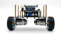
Mini-Wheelie Self-Balancing Robot

Self-Balancing Robot (Elektor project 240134)
This is Not a Toy!
The Elektor Mini-Wheelie self-balancing robot is intended as an educative project for engineering students, it is certainly not as a toy. The self-balancing robot is a popular topic in engineering courses, and this robot provides a suitable platform for it. Furthermore, the Mini-Wheelie has many extras to play with like an ultrasonic transducer, full-colour graphic TFT display and a power monitor, beside the wireless capabilities of the ESP32-S3.With the software loaded from this page (not the out-of-the-box demo), the robot has basic self-balancing functionality and can be controlled from a smartphone with the Dabble app. It is not an all-singing all-dancing gadget, it is a platform for the user to build and improve on.
The hardware for the Mini-Wheelie was developed by Makerfabs in cooperation with Elektor. The software that can be downloaded from this page was developed by and tested at Elektor. Everything is based on open-source projects found online and adapted for the Mini-Wheelie.
Software Installation
There appears to be an issue with the ESP32-S3 and Arduino on Apple computers. The solution is to enable USB CDC on Boot (not tested): Tools > USB CDC On Boot > EnabledArduino IDE The Arduino IDE configured for the ESP32-S3 microcontroller is required to compile and upload the software for the Self-Balancing robot. Refer to https://www.elektormagazine.com/labs/esp32-getting-started for detailed instructions on how to install the Arduino IDE for the ESP32. In this manual Arduino IDE V1.8.19 is used but the most recent V2 (V2.3.4 at the time of writing) can be used too.
Use ESP32 Arduino Core 2.0.17
The default Self-Balancing Robot software uses the Dabble library for Bluetooth control (https://thestempedia.com/product/dabble/). Dabble does not work (yet) with ESP32 Arduino Core V3.0.0 or higher. Therefore, when installing the ESP32 in the Arduino IDE, make sure to select version V2.0.17 (step 3 in the illustration below).
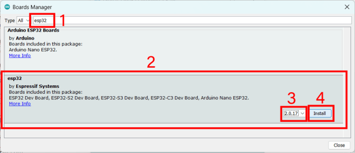
Select the ESP32-S3 controller board: Tools -> Board -> ESP32 Arduino -> ESP32S3 Dev Module

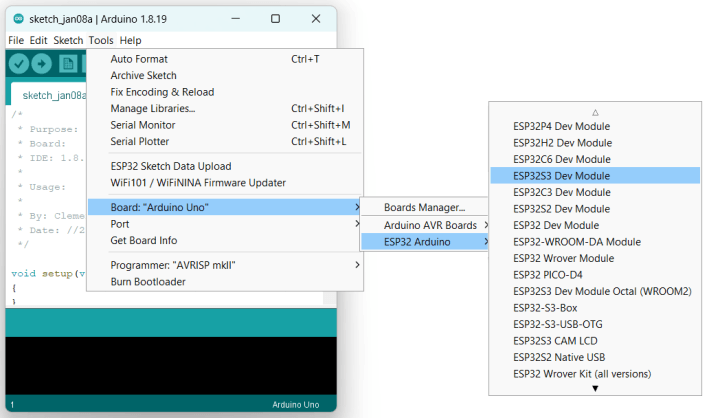
Select the port for the ESP32-S3 controller board: Tools -> Port

Download the Software
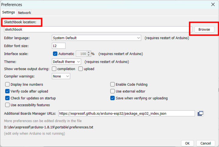
https://www.elektormagazine.com/labs/self-balancing-robot-with-maker-fabsDownload the archive and unpack it to the Arduino IDE’s sketchbook folder. If you don’t know where it is, check the Arduino IDE’s preferences (File -> Preferences).

If the Arduino IDE is running, close it and restart it.
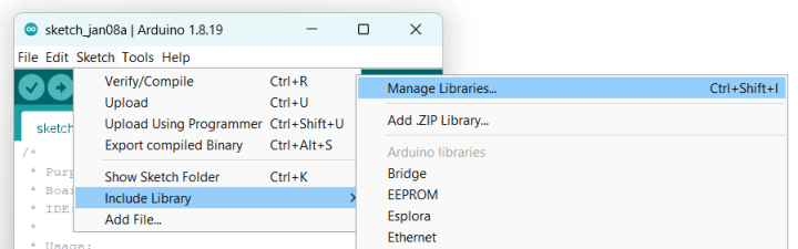
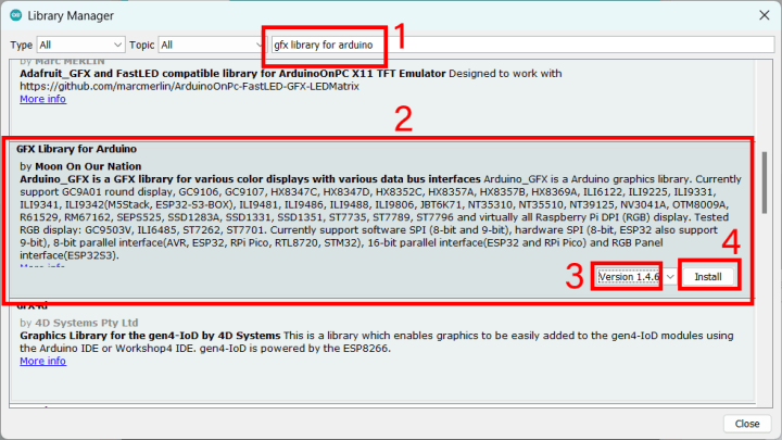
The download contains all the libraries except for the big graphics library, which you must install yourself. Install version 1.4.6 of the library “GFX Library for Arduino” by “Moon On Our Nation” using the Library Manager (Sketch -> Include Library -> Manage Libraries… or press Ctrl+Shft+I).


microSD Card
The download also contains a folder named sdcard. Using a computer, copy the files contained in this folder to a suitable microSD card and stick it in the microSD card slot of the robot.Calibration
For best results it is necessary to calibrate the software for the Self-Balancing Robot. To do so, place the robot in a fixture that lifts the robot so that its wheels can rotate freely. Also make sure that the robot is horizontal in all directions (the XY-plane).IMU Calibration
Upload the sketch SBRobot_IMU_Zero. Open the Serial Monitor and set the baud rate to 115200. Reset the robot and wait for the sketch to finish (takes a few minutes). The output of the sketch will look something like this (your values will be different):XAccel YAccel ZAccel XGyro YGyro ZGyro
[-2387,-2385] --> [-9,4] [975,976] --> [-6,14] [1242,1243] --> [16379,16393] [102,103] --> [0,3] [-60,-59] --> [-2,1] [72,73] --> [-1,1]
[-2387,-2386] --> [-9,1] [975,976] --> [-9,14] [1242,1242] --> [16379,16385] [102,103] --> [0,3] [-60,-59] --> [-2,1] [72,73] --> [-3,1]
[-2387,-2386] --> [-16,1] [975,976] --> [-8,14] [1242,1242] --> [16383,16385] [102,103] --> [0,3] [-60,-59] --> [-2,1] [72,73] --> [-2,1]
-------------- done --------------
Enter the offset values in the sketch SBRobotDabble (somewhere starting around line 100). Your values will be different, do not keep the default values:
#define X_OFFSET_ACCEL (-2387)
#define Y_OFFSET_ACCEL (975)
#define Z_OFFSET_ACCEL (1242)
#define X_OFFSET_GYRO (102)
#define Y_OFFSET_GYRO (-60)
#define Z_OFFSET_GYRO (72)
#define Y_OFFSET_ACCEL (975)
#define Z_OFFSET_ACCEL (1242)
#define X_OFFSET_GYRO (102)
#define Y_OFFSET_GYRO (-60)
#define Z_OFFSET_GYRO (72)
Motor Calibration
Upload the sketch SBRobot_Motor_Compare. Follow the instructions at the top of this sketch to find the minimum motor speed and motor speed corrections left and right. Enter these values in the sketch SBRobotDabble (around line 109 for MOTOR_MIN_ABS_SPEED and line 125 for motor_speed_multiplier_left and motor_speed_multiplier_right). Your values will be different, do not keep the default values:#define MOTOR_MIN_ABS_SPEED (55)
…
double motor_speed_multiplier_left = 1.0; // R_max/L_max
double motor_speed_multiplier_right = 0.97; // L_max/R_max
…
double motor_speed_multiplier_left = 1.0; // R_max/L_max
double motor_speed_multiplier_right = 0.97; // L_max/R_max
With the adjustments made, upload the sketch SBRobotDabble to the robot. Make sure to compile it with the ESP32 Arduino core 2.0.17 (or lower, see above). Disconnect it, switch it off, switch it on again and carefully place it on the floor. Make sure there is enough free space.
Install Dabble on a smartphone or tablet, see https://thestempedia.com/product/dabble/
Use Dabble in Gamepad mode. Do not connect the smartphone to the 'SBRobot' Bluetooth device, let Dabble do it for you.
Place the robot upright, keep it up with a hand or a foot so you can release it easily.
Switch on the robot. Wait for the connect message to appear on its display.
Connect the Dabble app to the robot. When the app is connected (a smiley is shown), the robot starts to balance.
Up/Down/Left/Right only work separately, they should not be pressed together. Be careful, remote control is quite complicated, and it is easy to lose control. The robot may fall over and even jump around.
It may be surprising, but the robot balances best on a rough surface. An uneven surface prevents the robot for gaining too much speed and get out of control.
The default PID settings will probably work reasonably well but adjusting them may improve the robot’s balancing performance. The PID parameters are found at line 165:
double Kp = 22;
double Kd = 2;
double Ki = 40;
double Kd = 2;
double Ki = 40;
Kp (P = Proportional) has the most influence. High values will make the robot too nervous, low values will make it too slow. Ki (I = Integral) and Kd (D = Derivative) are used for fine tuning. Use small increments/decrements when playing around and be patient. Decimal values are accepted.
Power Monitor
A power monitor is available for monitoring battery voltage and motor power. This can for instance be used to adapt the PID response to the battery level. See lines 24 to 27:#include
#define INA219_I2C_ADDRESS (0x40)
DFRobot_INA219_IIC power_monitor(&Wire,INA219_I2C_ADDRESS);
boolean power_monitor_ok = false;
#define INA219_I2C_ADDRESS (0x40)
DFRobot_INA219_IIC power_monitor(&Wire,INA219_I2C_ADDRESS);
boolean power_monitor_ok = false;
Discussion (33 comments)
tony1tf 3 days ago
tony1tf 9 hours ago
I mentioned previously that I had added a maximum speed number to stop the robot running away. Currently set at 200, and it can still run away. If I change it to 160, there's not enough motor power to keep it upright. I have a question to the designer(s) at Elektor - the Motor Compare code uses the hall sensors to measure motor speed, but these don't seem to be used in the Dabble code, as speed is just motor power input. Obviously, we could limit the speed by using the Hall sensors to sense robot speed, and keep the motor power available to the normal +/-255 limit to make sure it balances. Is Clemens Valens going to be showing new code for this in coming articles?
I note that the code in the Motor Compare uses interrupts:
attachInterrupt(digitalPinToInterrupt(CA1),hall_sensor_read_ca1,RISING);
attachInterrupt(digitalPinToInterrupt(CA2),hall_sensor_read_ca2,RISING);
attachInterrupt(digitalPinToInterrupt(CB1),hall_sensor_read_cb1,RISING);
attachInterrupt(digitalPinToInterrupt(CB2),hall_sensor_read_cb2,RISING);
Since we see that the execution time in the Dabble code is critical, will be have enough power in the ESP32 to be able to keep up with the Hall sensors and run the PID loop? Those of us not familiar with how Arduino code, C++ and the ESP32 work are obviously going to need some guidance on this. The ESP32 has two cores - will we have to use both?
For me this is all advanced stuff, so I am looking forward to the articles in Elektor - please ASAP!
Rudolf Köhler 3 days ago
Controller was Atmel mega32 with 16Mhz. And this vehicle runs till today, no timing problems, no unexpected resets like in the mini version. Hardware is very similar to the mini: two gear motors wih hall sensors in full H- bridges, similar balance sensors an so on. I had only one accident, when one of the H-bridge transistors died: was not so good for me standing on the vehicle......
Do you have an idea, where the unexpected resets come from, either stack overflows or timing problems? the code is for me to complex to understand it completely, think you have more experience in c++ programming.
so far for now, hope there will be some comments from the elektor lab or a new sketch version in the future.
rgds Rudolf
tony1tf 2 days ago
Just to put you in the picture - I am old and learned on 6800/6502 BASIC, machine code and assembler.
Never learned Object Orientated languages, so I am as perplexed at the way C++ works as any novice. I have to just copy, edit and play to make any sense of it. As I am retired, I can spend a lot more time experimenting than others, but expect that others will have much more knowledge. That's why I am hoping that Elektor will publish a really comprehensive guide to what is driving this robot, as it looks like a great development tool.
As I mentioned in a post here, I have enabled the Ultrasonic sensors, but since the robot doesn't move properly, the forward facing detection doesn't get it out of corners or anything useful. I have a small 3 wheeled car from Adama Robotics which has sensors, line follower, LEDs etc, and can be programmed from Scratch, and also Arduino C++ - very much aimed at school kids, and it would be great if this Elektor robot got up to their standard.
Tony
Rudolf Köhler 1 day ago
when I read your lines, I feel back in my youth. My first experiments were with the 6800 with two phase clock generator about 1MHz, I remember the first single board with hex input and output on 7segment led, operating system was 1kB Eprom with mini or micro -bug. nxt step was a 2kB Basic interpreter. little bit later i got a crt terminal with keyboard, forgot the name of this rig, but it was must have. later on I built a floppy comtroller for 8 inch Floppy drives (surplus ibm) , expand ram to 32kB wired without a pcb on standard cards for dil ttl ic, highlight was my first harddisk with unbelievable 5MB!. years later the first ibm with dual 5" floppy 1MHz clock rate.........and so on
beside this I programmed in assembler the intel 8049 and then all the atmel tynies etc with bascom and avr studio whit atmel isp programmer . arduino was then a very convenient system, but with all the libraries I lost the overview of coding. now I am doing like you try and error....
with the mini wheelie I think I must replace one of the motors to get better results. balancing is done mainly with one motor, the other is to week. try to get a new one from elektor.
keep in contact
Rudolf
Nephrondoctor 2 days ago
Rudolf Köhler 6 days ago
the former settings were good with very low battery
Whith the new settings and full battery the wheelie runs very stable on the floor with no carpet.
Kurt K. 4 days ago
I have found that varying the K parameters worsens the behavior rather than improving it and have stuck with the standard values. You have essentially done the same.
What I still want to solve: If I stay on the forward or reverse button for more than half a second, it accelerates unexpectedly and I then have to quickly tap the button for the opposite direction, otherwise it keeps going faster and faster.
It reliably stops for less than half a second.
Is that the same for you?
samro 3 days ago
Kurt K. 2 days ago
The best way to find out the best value is to use the buttons "Select" and "Start" to modify it up and down and to write the values to the display. Then I adjusted originalSetpoint in the source now to 181.
And the best is: Wheelie is significantly more stable, when the motors are mounted as shown in the PDF, not like shown in the video!
I believe that the lower center of gravity makes it easier for the PID algorithm to regulate.
Of course you have to invert the sign of variable output:
motor_controller.move(-output+speed_offset_l,-output+speed_offset_r, MOTOR_MIN_ABS_SPEED);
motor_controller.move(-output, MOTOR_MIN_ABS_SPEED);
Rudolf Köhler 4 days ago
27/2/40
motors are very different left motor needs without power much more torque to turn by hand !
motor test:
lright motor starts with 48 and stops with 37
left motor starts with 70 and stops with57
109 (70)
130 l 1.1
131 r 0.9
160 (40)
163 (3)
all the behavior of my wheelie are nearly the same. If the space is big enough, I can handle it very good, but sometimes it has unexpexted resets and therefor lost connection with the smartphone. If you watch the original video you can see the same behave.
rgds Rudolf
Kurt K. 2 days ago
Yes, sometimes I observe a reset as well.
I have the significantly feeling that the lower center of gravity makes it easier for the PID algorithm to regulate.
Next I'll switch to the accelerometer mode variant of the gamepad. My thumbs are so dry, that not every time the touch field is recating. With the tilting technique, I don't have to constantly check where my thumbs are resting and only have to hold the phone at a slight angle. I can't wait to see how it feels!
Rudolf Köhler 1 week ago
To rule out possible errors, I dismantled the wheelie, i.e. installed the position of the motors as in the video and used the unchanged original software with the offset corrections. The wheelie swung back and forth until it tipped. With Kp=50, . Kd=3 and Ki=45 it comes to a standstill after a short pendulum. however, control via dabble is hardly possible. However, the proposed changes to the controls only make the thing uncontrollable. My question: when I hold the wheelie high and balance it to test, the right motor turns fully left or right. However, the left motor only rotates at a very small angle of inclination and then stops. I don't understand this asymmetrical behavior. Another problem is that the motors are very uneven in their start-up behavior, which means that the wheelie does not drive away straight and correction is difficult to make. Left right is swapped anyway. Does anyone have an idea why the unusual behavior is? (Übersetzung durch Google)
ElektorLabs 1 week ago
Self-balancing only works when the robot is on a flat surface and the motors can respond to the control algorithm. It doesn't work when placed in a rig or held in your hand.
Rudolf Köhler 4 days ago
PDI: 27/2/40
motors are very different left motor needs without power much more torque to turn by hand !
motor test:
lright motor starts with 48 and stops with 37
left motor starts with 70 and stops with57
109 (70)
130 l 1.1
131 r 0.9
160 (40)
163 (3)
If the space is big enough, I can handle it very good, but sometimes it has unexpexted resets and therefor lost connection with the smartphone. If you watch the original video you can see the same behave.
rgds Rudolf
Rudolf Köhler 4 days ago
I will try to test the motors again with the motor calibrate sketch and take a picture.
rgds Rudolf
ElektorLabs 2 days ago
Rudolf Köhler 1 week ago
I didn't swap the motor cables, but rather the pins in the software, but I have a fundamental problem. On my wheelie, one motor rotates at a slight angle without ground contact, while the other motor rotates fully left and right. Is this intended behavior in the software or a bug? My question is: Does anyone already have corrected software that I can use as a starting point for further changes, except for the gyro corrections? Thanks Tony1tf for the code, I will try it later. One minor question: Has someone tried to charge the battery with the delivered charging adapter?
samro 1 week ago
I also built the wheelie and he is balancing quite well on place but i am wondering about the left/right direction definitions using dabble gamepad. When i press the up pad a red rectange is shown on the top side of the display (near infrared sensor). Pressing Down pad shows a red rectangle on the USB side. But now:
Pressing right pad shows red rectangle on right side but the wheelie turns left because the wheel seeds up.
Do any of you have the same problem or is this intentional?
And why the blue arrows (u/d/l/r) stored on the sdcard are not displayed?
samro 1 week ago
Still confusing when pressing left pad he turns right. But on video it's the same.
Kurt K. 1 week ago
I simplified the code part, which turnes the wheelie left and right :
Calling speed_adjust is not necessary.
With some enhancements I can now adjust the Kp, Ki and Kd parameters with the gamepad Cross, Circle, Triangle and Start/Select.
I can only discover that shaking increases when I modify from KP=22, Ki=40 and Kd=2.
That means for my understanding, that this values are already optimized.
Still have the problem, the wheelie accelarates on a smooth surface, when I tap a little bit too long on the forward or backward button.
And I am far away to put a drinking carton stable on the wheelie!
Driving on a carpet the constant TILT_OFFSET of 4 is sometimes to small and for parquet almost to high.
Next I will turn the motors 180° as it was described in the first manual and invert the rotation direction in the software (*-1). I think because the center of mass will be slightly lower and the PID algorithm has not to work so hard.
Kurt
tony1tf 1 week ago
Pleased to see someone else working on the code.
I have also abandoned the speed adjust call and incorporated some code in the main loop. I have stopped using a speed offset which is added or subtracted, but instead using a factor which is multiplied or divided into 'output'. This seems to give slightly better results. I have also added a maximum speed to stop the robot running away into things when tilted for forward and back (and turning). I have also enabled the ultrasonic sensor with the 'NewPing' library.
We are slowly getting there, but I wouldn't fancy balancing anything on it yet.
Tony
Code snippet:
ElektorLabs 1 week ago
The problem on a smooth surface is that the robot doesn't encounter anything that will stop it from falling over. To improve this, a way might be to decrease the tilt value periodically to keep control over the speed.
Making the robot lower has, as a matter of fact, the inverse effect of what you would expect, as it will also lower the position of the IMU. The result is a lower amplitude control signal, making it harder for the PID controller to use it.
tony1tf 1 week ago
Press boot and press and release reset, then release boot.
Thanks for the advice Rolf Wälty.
I thought this was something you only had to do once, but I do it every upload.
tony1tf 1 week ago
It's fun to tune the algorithm live. A bit of forward and back can make it unstable, then you have to play with damping down thew oscillation.
Now I can work on the left and right algorithm.
I'll try and revert to how it was as suggested by Elektor, but I don't remember that working for me. Perhaps setting up with the other code is more critically important, but I did use a spirit level to set it up, so it wasn't far out.
Because of the ESP32 upload problems, it takes far longer to update the code than it's reasonable to expect. I'm succeeding about one in three attempts - the critical thing is only releasing the reset button just before upload takes place - that's between 4 and 5 seconds after I see the message about how much space is used.
It would be good to know if this is only a Mac problem, or if Windows users are also experiencing the upload failures. I wondered if it is concerned with the code itself where the Arduino is waiting to connect to Bluetooth - does that slow the USB response?
tony1tf 1 week ago
pid.SetTunings(Kp, Ki, Kd);
You can't re-use the initialisation call with the parameters because that kills the response, and the robot falls over.
tony1tf 1 week ago
For reasonable stability, My Kp = 30, Kd = 2, Ki = 70.
The display shows 3 numbers - the PID output, PID input from the level sensor, and the PID setpoint.
I can't make the left and right speed inputs work properly, because the self balancing algorithm always seems to override it, or it all goes unstable and hits the deck over and over.
Lots of stuff commented out, and lots of comments added.
Enjoy if you can!
ElektorLabs 1 week ago
Unless you modified the mechanics of the robot, the assembled kit should balance quite well with the default software and settings. It worked fine on all of our prototypes. I suggest you revert to the default settings and try to improve from there. Make sure to execute the calibration sketches with a horizontally placed robot.
rpt007 1 week ago
I really admire your patience, power and willingness to drive this project to a success.
It would be a big step forward if you would support Elektor by creating a development story how to deal with this DIY kit in the view of a customer and report about your experience with the kit.
All of the current and future buyers would benefit. As for me this project ends up here for the time being and might come back to a robot project one day when time allows and I get what I can expect based on the advertisment of a kit.
Good luck
Raimund
tony1tf 1 week ago
There are three identical named calls - one with two variables, one with three and one with one. How does one of them get selected without an error?
LMController::move(int leftSpeed, int rightspeed, int minAbs Speed)
and LMController::move(int speed, int minAbs Speed)
and LMController::move(int speed)
ElektorLabs 1 week ago
This is how C++ works. The compiler selects the correct function based on the variables passed to it. In case you are unsure about C++, there are plenty of tutorials on the Internet.
tony1tf 1 week ago
I grew up in the days of machine code programming, so I only edit and use C++ without any proper knowledge of it or any structured language.
The tutorials show that we are talking about "Function Overloading".
In other languages, that would have caused an error if you don't supply the correct number or type of parameters. C++ is clearly very forgiving in that respect, but so much goes on behind the code that it is difficult for the likes of me to understand it. I have to realise that I just have to be a user and accept it!
tony1tf 1 week ago
I have added #define __LOG_INPUT__
It can be undefined to stop the display.
I have now turned off logging to the serial port.
I have edited "show float" to take an integer to position the value in the first, second or third position on the screen.
Also using the t_now variable to increase the display update time to 1 sec. (Had to move it's definition to the start of the code).
Lots of other tweaks.
I'm hoping I can eventually make the robot turn left or right, but I'm still really struggling with that.
I can post code whenever anyone wants me to. It's continually changing.
Tony
ElektorLabs 1 week ago
See line 652:
.
tony1tf 1 week ago
I'll continue experimenting. What speed offset are you using?
tony1tf 1 week ago
Is anyone else experiencing this problem. I might try the Arduino forum to see if there is a solution.
Errors:
Sketch uses 1087533 bytes (82%) of program storage space. Maximum is 1310720 bytes.
Global variables use 64540 bytes (19%) of dynamic memory, leaving 263140 bytes for local variables. Maximum is 327680 bytes.
esptool.py v4.5.1
Serial port /dev/cu.usbmodem11101
Connecting...
Chip is ESP32-S3 (revision v0.2)
Features: WiFi, BLE
Crystal is 40MHz
MAC: 24:ec:4a:0a:ab:b4
Uploading stub...
Running stub...
Stub running...
A fatal error occurred: Unable to verify flash chip connection (No serial data received.).
tony1tf 1 week ago
esptool.py v4.5.1
Serial port /dev/cu.usbmodem11101
Connecting...
Chip is ESP32-S3 (revision v0.2)
Features: WiFi, BLE
Crystal is 40MHz
MAC: 24:ec:4a:0a:ab:b4
Uploading stub...
Running stub...
Stub running...
Changing baud rate to 230400
Changed.
Configuring flash size...
Flash will be erased from 0x00000000 to 0x00003fff...
Flash will be erased from 0x00008000 to 0x00008fff...
Flash will be erased from 0x0000e000 to 0x0000ffff...
Flash will be erased from 0x00010000 to 0x00119fff...
Compressed 15104 bytes to 10430...
Writing at 0x00000000... (100 %)
Wrote 15104 bytes (10430 compressed) at 0x00000000 in 0.3 seconds (effective 461.4 kbit/s)...
Hash of data verified.
Compressed 3072 bytes to 146...
Writing at 0x00008000... (100 %)
Wrote 3072 bytes (146 compressed) at 0x00008000 in 0.0 seconds (effective 496.0 kbit/s)...
Hash of data verified.
Compressed 8192 bytes to 47...
Writing at 0x0000e000... (100 %)
Wrote 8192 bytes (47 compressed) at 0x0000e000 in 0.1 seconds (effective 630.1 kbit/s)...
Hash of data verified.
Compressed 1087904 bytes to 643555...
Writing at 0x00010000... (2 %)
Writing at 0x0001d791... (5 %)
Writing at 0x0002a739... (7 %)
Writing at 0x000386d4... (10 %)..............
tony1tf 1 week ago
Then randomly worked again.
This is a mystery that needs solving.
ElektorLabs 1 week ago
tony1tf 2 weeks ago
Let's see how it works out.
One thing not directly explained is that the Python code needs to keep up with the interrupt driven PID system. If you put too many diagnostics in, the robot can't stand up. I have to very carefully adjust the wine box support to see what the PID algorithm is doing via the serial port.
A much better solution to tuning the algorithm would be if important parameters were stored on the SD card and could be updated remotely.
I'll ask the question again - is there going to be an article(s) on this to help guide us all?
Tony
ElektorLabs 2 weeks ago
All the button handlers are there, the ones currently not used are commented out. You can either use those or repurpose another. The robot's display can be used to show parameter values, or use the serial port (or both).
To answer your other question, yes, an Elektor article about the Mini-Wheelie has been planned.
P.S. The software is in C++, not Python.
tony1tf 2 weeks ago
I have got the robot to stay upright by increasing the PID values - now using:
double Kp = 35; // started at 22. Now changed to nearer the original code software values
double Kd = 2;
double Ki = 150;
From what I can see, the left and right speed inputs are always overwritten by the PID algorithm, and don't have any effect. I'm still experimenting, and will post code if I can make it work, but pointless ATM as it will just confuse.
Tony
ElektorLabs 2 weeks ago
Moving forward or backward is even more complicated, because the robot must be forced out of balance. You can do this by introducing a tilt angle. However, when tilting, the robot is no longer balanced and only speed will prevent it from falling over. To make the robot stop, the tilt angle must be decreased gradually, so the PID can keep up with the change. When done too abruptly, the direction may change, swapping forward & backward. In short, it is not as simple as it seems.
In the default software available on this page, turning is implemented simply by spinning only one wheel and while not moving at the same time. By first moving and then turning while it is still moving, the robot can turn. Turning and moving at the same time is complicated and requires delicate control.
The default software is implements moving forward and backward and turning, but not at the same time. Commented parts in the code are not used and are the result from experiments. They were left in the code so you can see what you can try or not.
Dabble was used because we had used it before. Unfortunately, it is not keeping up with the evolution of the ESP32 boards package. Replacing Dabble by another control library might be useful. Also, there is no need to use Bluetooth, Wi-Fi or ESP-NOW are other options.
tony1tf 2 weeks ago
I couldn't believe my eyes when the battery went down to 1% and reset.
tony1tf 2 weeks ago
https://www.instructables.com/Arduino-Self-Balancing-Robot-1/
Rolf Wälty 2 weeks ago
EN0212808ID 2 weeks ago
Do you explain how to fill thse parameters :
// Motor 0 - left motor when ESP32S3 antenna is pointing forward.
const int ENA = 46;
const int IN1 = 7;
const int IN2 = 18;
const int CA1 = 16;
const int CA2 = 17;
// Motor 1 - right motor when ESP32S3 antenna is pointing forward.
const int ENB = 45;
const int IN3 = 10;
const int IN4 = 11;
const int CB1 = 9;
const int CB2 = 47;
Thanks a lot !
tony1tf 2 weeks ago
Tony
tony1tf 2 weeks ago
The code and comments are clearly the same as in the Elektor code, so we can begin to delve:
https://drive.google.com/file/d/1kjSLPwbM_tJDTGydVms634JaDCiZW5SK/view
tony1tf 2 weeks ago
It goes back to 2012, so hardly a new project!
https://github.com/satinder147/code-for-self-balancing-robot-using-arduino/blob/master/code%20for%20self%20balancing%20robot
rpt007 2 weeks ago
Bought the kit a few days, before my grandson came to visit us and I thought it would be a surprise and fun for him to play with the little wheelie.
As retired electronics engineer with about 10 years+ experience with Arduino stuff and complex DIY designs (even for an industry branch ...) I thought this is a piece of cake. OMG !! Got the kit and built it up in an hour or so -
never thought that this wheelie project is a kind of PITA.
Before building I found in this discussion a helpful comment (thanks @DE0077163ID) about the pdf-instruction of mounting the motors the wrong way (hello, good morning, how's that?). Besides of that the mechanical part was ok.
Then the software disaster began. No information about what USB-port to use and no explanation about the reason to have two USB-C ports (ok, one titled as TTL and the other ..).
I am on a Mac OS main time, but also have a Win10 PC for some special software which can't be run on Mac (even no chance with Parallels etc.) - both Arduino packages (1.8.19 and 2.04) on both OS didn't lead to a success.
Having installed all required libraries in the correct revisions the sketches all compiled without errors, but they failed to be uploaded successfully to the ESP32-S3 - never finishes the upload cycle and hangs always in an endless loop.
My research showed that there is a known issue with the "S3" not being able to automatically finish the upload process - maybe only with some tricks and pressing / holding boot/reset buttons in a defined sequence.
Well, as engineer this is normally a challenge to get the thing up and and run (maybe I am lucky to find the right instructions somewhere). But I think of all the wasted time of life having assumed to buy a well documented and tested product and have it set up well before my grandson was coming. I never meant this project as a development for the buyers. How many people will enthusiastically buy the kit and will be left disappointed? And not all of them are either experienced microcontroller engineers or have time or skill to finish such a project
And when I read that the Ultrasonic distance sensor (which btw is not precisely placed on the pcb as it touches the ESP's antenna on one side and the pcb surface on the other) is not even yet used in the software ... What the heck are you showing in the advertisement videos????
I am an Elektor reader since my university time in the late 70's and registered member over the past years, learnt a lot and built dozens of projects in those decades. But this project is a total fail and disappointment if it goes on like this.
Dear people of Elektor - what do you think to sell such a lousy, under-documented and failure-oriented product for almost 100€ ?? And hey - who in Elektor labs ever built this kit from scratch and didn't run into those kind of issues?
Hope, you listen to your customers carefully and come out with a well documented and failure-safe instruction with a step by step process how the S3 can be convinced to finish an upload. If not, pls declare this project as a kind of "banana product" to be developped by the buyers themselves and sell it for half the price.
Your not very amused customer
Raimund
ElektorLabs 2 weeks ago
Thank you for reaching out and sharing your concerns regarding the Mini-Wheelie. We appreciate your feedback and understand that product expectations can vary based on individual use cases. We would like to clarify that the Mini-Wheelie is designed as an educational development platform intended for learning, experimentation, and robotics development. It is not classified as a toy for children, and its features, documentation, and intended audience reflect this purpose.
If you were expecting a consumer-grade toy, we sincerely regret any misunderstanding. Our product is aimed at students, educators, and developers who wish to explore robotics, programming, and hardware integration in an educational setting.
That said, we are always looking to improve our communication regarding product positioning and would be happy to discuss any specific concerns you encountered. If you require guidance on how to best utilize the Mini-Wheelie within its intended scope, please let us know, and we will be glad to assist you. Should you wish to explore return or exchange options, please refer to our return policy, and feel free to contact our support team for further assistance.
rpt007 1 week ago
Your Customer support sent me the instructions to send the Robot back.
I have sent them a suggestion how to avoid future misunderstandings and how to position this product so that potential buyers exactly know what they can expect buying the kit.
I also appreciate your willingness to support the project by publishing the mini-wheely development in one of the next Elektor publications. May I suggest that you contact @tonyltf and ask him to be your co-author bringing in the view of an unbiased customer. This would give a far better positioning of the kit, showing that progress is doable until the Robot eventually does what your buyers expect.
Just my 2Cents and for the time being I am out here.
Raimund
rpt007 2 weeks ago
Indeed I expected a functionable toy - there is no indication around the product advertisement which underlines that it is just a learning, educational project which isn't yet finished at all. All the information around this kit is indicating that you'll get something to build mechanically, program the ESP32 with the firmware that comes with the kit and then you'll get a running wheelie.
Now this is very far away from being even a reasonable project which might have a chance to do what is expected in a reasonable time of development. The accompanying video shows the kit in a wooden wine case, being tuned ... How's that when you wrote as reply to Tony that this won't work as the wheels have to have contact to ground ... ??
And no coding for the built in Sonar module, known upload issues with the S3 ... and so on and so on..
Dear people of Elektor -> pls have a very close look at this project and come out with a development path which can be followed step by step. Otherwise you will disappoint more people and loose your customers. My impression is, that the project was compiled by some people which were/are NOT talking to each other, NOT working together with a clear resposibilty and agenda .. assuming that the other guy does this or that and has definitely thought of .. and thus the result is like it is.
I have contacted the German service team to instruct me how to send the kit (assembled or disassembled as they'll like) back. Currently I have other priorities and no time to spend more energy into this half-ready thing.
Raimund
ElektorLabs 2 weeks ago
tony1tf 2 weeks ago
I am in the process of tweaking the SBRobotDabble code - adding lots of 'Verbose' print statements to see what the hell is going on. I have now even found that code to move forward and backward is commented out!
I don't mind working on an experimental project, if that's what it is advertised as. The platform is good with powerful motors. And I have taken up the suggestion of using a wooden wine box to keep the unit off the ground and flat while investigating.
A long way to go to get it to a state where ordinary folk are going to be able to use it.
rpt007 2 weeks ago
Hope, Elektor reads, understands and commits to better support this project.
Currently I am very busy with other priorities so very little time to keep more attention to the wheelie. Only some evening hours left to go for it. This is what added more frustration on my side as I looked at the project as kind of relaxation ... ;-((
If I should happen to run into advances I will all let you know. But I can't say, by when I'll come to this.
Btw:
my SD card contained already all of the images which come with the software-zip package plus some more. So there was no need to write the files onto the SD card as instructed. It seems that the whole project is in a "in between" status and that Elektor people just imported it, never testing themselves and having no idea what is in the firmware package or on the SD card.
Quality department outsourced or on holidays?
tony1tf 2 weeks ago
A fatal error occurred: Unable to verify flash chip connection (No serial data received.).
tony1tf 2 weeks ago
I can see that the Ultrasonic pins are shown in the code, so we don't need to guess them, but there is no code to do anything with it yet.
Again - questions to Elektor - are you going to publish more and when? Is there a link to a previous project that this is based on?
I notice that there is an article on PID tuning which could be useful for this one.
tony1tf 2 weeks ago
There needs to be input controls to adjust the parameters to cope with low and high friction surfaces, as I am finding it impossible to get my robot stable on a smooth surface. With it set up to be stable on a rough surface, the movement controls are very insensitive, and on a smooth surface it just runs away and falls over. I presume that we should use the other 'gamepad' controls to enable more functions on the robot.
Come on Elektor you are letting down your readership at the moment. I have been reading Elektor since it was first published!
Chinchole 2 weeks ago
I have the same problem like tony1tf:
Have people been able to use the serial monitor when running SBRobot_IMU_Zero? I was able to upload the sketch, and have set the baud rate to 115200, but the code doesn't talk to the serial monitor. I see no initialisation message "Initializing I2C devices...".
it's dosen't work...
i'm waiting 10min and nothing.
i'm on platformio
my ini
[env:esp32-s3-devkitm-1]platform = espressif32board = esp32-s3-devkitm-1framework = arduinoboard_build.mcu = esp32s3monitor_speed = 115200lib_deps = moononournation/GFX Library for Arduino@^1.4.6 Thank you
Rolf Wälty 2 weeks ago
Tools > USB CDC On Boot > Enabled
and
Tools > USB DFU On Boot > Enabled
The ESP32-S3 uses both CDC and DFU to connect via USBC direct and start the program after upload.
Error uploading:
To reset the boot. Press boot and press and release reset, then release boot.
Hope it helps.
Jacques Baudoux 1 week ago
Chinchole 2 weeks ago
it's the USB flag.
on platformio add (on the platformio.ini)
Rolf Wälty 2 weeks ago
When starting 'SBRobot_Motor_Compare' and the command 'c' both motors are turning. Unable to just start left motor with the 'l' command. This can be done with the 'u' command.
This is a fanny behaviour.
ElektorLabs 2 weeks ago
To experiment with one motor at a time, open the Serial Monitor and use the 'l' or 'r' command to select the motor. Then use 'u' and 'd' to adjust its speed. Note that it is possible to send strings like 'uuuuuuuuuuuuuuuu' or 'ddddd' to send multiple values.
The video on this page shows how to do this.
Rolf Wälty 2 weeks ago
samro 1 week ago
Ich habe den selben Fehler auch gemacht! Lol: Wer lesen kann ist klar im Vorteil....
(I made the same mistake too! Lol: Those who can read have a clear advantage....)
tony1tf 2 weeks ago
Tools > USB CDC On Boot > Enabled
tony1tf 2 weeks ago
I also note that only the right hand USBC connects to my Macbook. There is no port when I connect to the left hand one. I notice on the video that he connects to the left hand one, so I presume both should be active.
It's very awkward having no info on this board, and just having to take pot-luck.
Jacques Baudoux 2 weeks ago
A simple sketch
Serial.begin(115200);
Serial.println("Hello world");
does not display anything on monitor
tony1tf 2 weeks ago
I am using a MacBook too, so the command Tools > USB CDC On Boot > Enabled
works to get the serial monitor working. I found it in the main Arduino forum with the subject:
COM Port Issues and odd Serial Monitor Behavior, Adafruit ESP32 Feather
I havn't checked the left USB C port yet - I'm not touching anything till I have got the IMU figures ;-)
Tony
tony1tf 2 weeks ago
ElektorLabs 2 weeks ago
The microSD card does not include firmware, it has some files on it used by the software. The default out-of-the-box firmware does nothing besides showing that the motors & display work.
tony1tf 2 weeks ago
There is a boot button and a reset button, but they just restart the software.
The instructions talk about loading the necessary Arduino software. So is the Makerfabs software just an irrelevance, and I have to start from scratch?
Gerlektor 3 weeks ago
How to debug the file?
ElektorLabs 2 weeks ago
For more information on the compilation error, please enable “Show verbose output during” for compilation. (File ⇾ Preferences). Then post the full output using copy-paste, not just a screenshot.
Kurt K. 3 weeks ago
both photos on page 3 (I. Assemble the motor and tire) which shows the motor mounted in the bracket are wrong. The motor has to be mounted shifted as shown in the video.
Otherwise the rotation direction of the motors is the other way round what prevents a successful balance!
FR0159115ID 3 weeks ago
I have mounted the motors as shown in the video and it's ok .
Thank you very much for this information.
tony1tf 2 weeks ago
It still just falls over and spins round and round, so I guess the provided software on the SD card needs updating and proper calibration done.
Kurt K. 3 weeks ago
I found, that the value TILT_OFFSET must be increased to 3 (line 163). Otherwise the wheely does not try to go forward or backwards.
Rotating left or right is still unsatisfactory. The original value for SPEED_OFFSET is 40. No rotating does happen at all. I increased it to 105. Now it stutters pressing the left or right button. Sometimes one stutter step is strong enough to rotate wheely a little bit.
My minimum motor values are approx, between 82 und 143.
My next step is to understand the feeback control part of the software. With this knowledge I hope to find a way to make the rotation more smooth.
I am interested on other experiences!
Regards,
Kurt
tony1tf 2 weeks ago
Wilhelm Meier 1 month ago
ElektorLabs 2 weeks ago
Rolf Wälty 2 weeks ago