

Small audio mixer

With a simple design, it will provide you with quite a few services
Version A (ALPS Potentiometers)
The project consists of 2 PCBs:
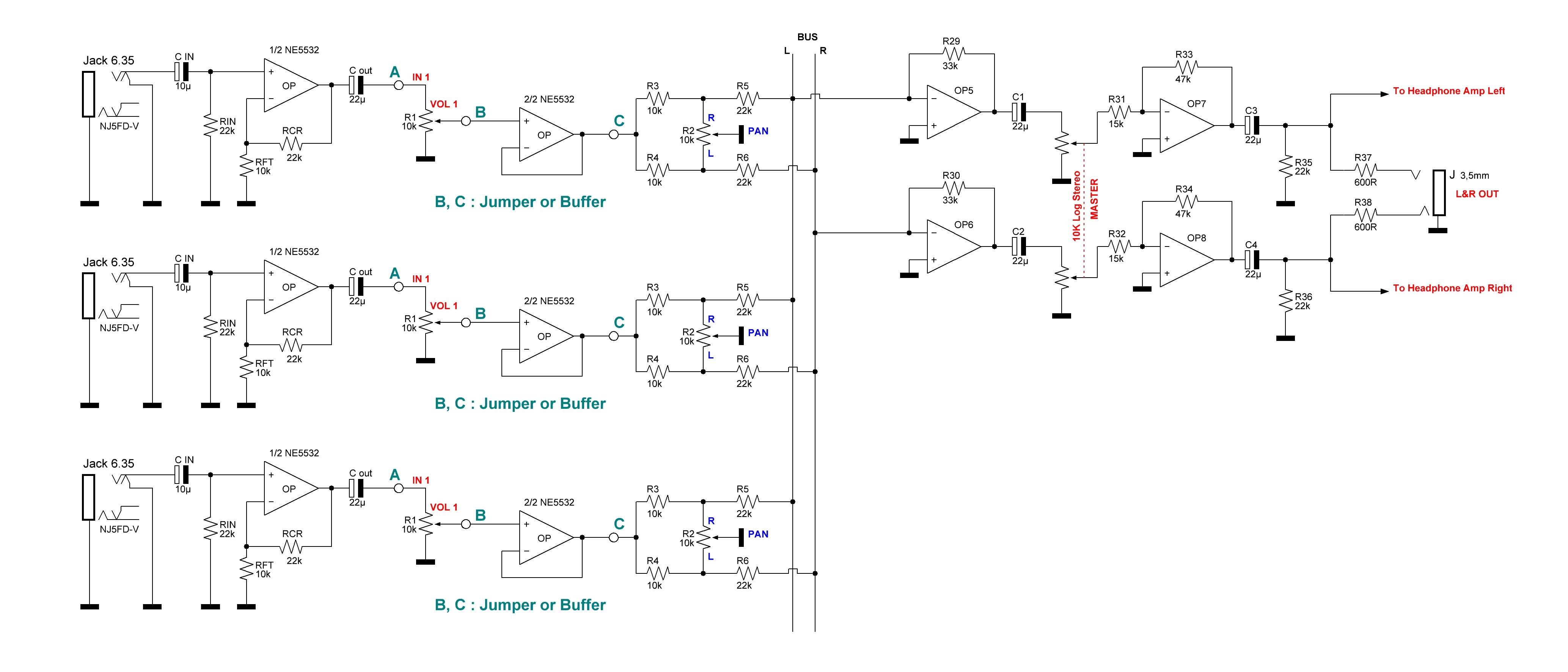
The inputs, levels, Pan Pots, as well as the L&R Bus are located on the first board which initially can accommodate 8 signals but can be cut according to individual needs. In my case, it’s a 3x2 mixer for monitoring.
Channel 1 is the sound pickup microphone, channel 2 is a GSM return and channel 3 is an auxiliary return. All this is of course preceded by adequate preamps. In1, In2, In3 are obviously at line level.
The second board provides the mixing and output stage function.
At the schematic level, we are really in simplicity.
R1, R7, R13 adjust the input dosages.
R2, R8, R14 assumes the function of Pan Pot to assign in stereo space. For my project, I chose models with a central notch.
Here is another assembly with virtual masses for the Pan Pot. To send to the right, junction R3, R5 is grounded so nothing to the left. Same when junction R4, R6 is grounded nothing on the right.
OP1 & OP2 are in summing mode. A potentiometer adjusts the output level followed by a stage (OP3, OP4) which provides a gain of 10 dB.
Here is the reference for ALPS potentiometers :
The project consists of 2 PCBs:
The inputs, levels, Pan Pots, as well as the L&R Bus are located on the first board which initially can accommodate 8 signals but can be cut according to individual needs. In my case, it’s a 3x2 mixer for monitoring.
Channel 1 is the sound pickup microphone, channel 2 is a GSM return and channel 3 is an auxiliary return. All this is of course preceded by adequate preamps. In1, In2, In3 are obviously at line level.
The second board provides the mixing and output stage function.
At the schematic level, we are really in simplicity.
R1, R7, R13 adjust the input dosages.
R2, R8, R14 assumes the function of Pan Pot to assign in stereo space. For my project, I chose models with a central notch.
Here is another assembly with virtual masses for the Pan Pot. To send to the right, junction R3, R5 is grounded so nothing to the left. Same when junction R4, R6 is grounded nothing on the right.
OP1 & OP2 are in summing mode. A potentiometer adjusts the output level followed by a stage (OP3, OP4) which provides a gain of 10 dB.
Here is the reference for ALPS potentiometers :
RK09L1140A5E Vertical 10K log (Track Level )
RK09L114001T Vertical 10K Lin with center detent ( Pan Pot )
RK09712200MC Horizontal Stéréo 10K log ( Master )
Version B (BOURNS Potentiometers)
The diagrams & PCB having been modified, it is an increased version with possibilities of an input stage.
As soon as possible I will publish all these changes
Here is the reference for BOURNS potentiometers :
PTV111-3415A-A103 Vertical 10K log (Track Level )
PTV111-3220A-B103 Vertical 10K Lin with center detent ( Pan Pot )
PTV112-1417A-A103 Horizontal Stéréo 10K log ( Master )
Discussion (2 comments)

sjhebrock 10 months ago
I may be wrong because I haven't gone through the math, but intuitively, it appears the panpot position is going to have a significant effect on the level (and therefore the "linearity" of the level control) because of the very similar impedances of the level control and the panpot section. Personally, I'd use another op amp in between the two...
Reply

ERRYSON 10 months ago
As in my second implementation with Bourns potentiometers, I provided a jumper to insert a possible buffer, I also decided to place an input stage before the "level" potentiometer. This allows me to use one NE5532 rather than 2 x NE5534.
The input jack here is a compact NJ5FD-V since the pitch between channels is 20.32 mm.
The input jack here is a compact NJ5FD-V since the pitch between channels is 20.32 mm.
Reply
Show more
4 Comment(s)

Updates from the author
ERRYSON 2 months ago
ERRYSON 3 months ago
ERRYSON 4 months ago
ERRYSON 4 months ago
https://www.neutrik-france.com/fr/product/nrj6hf
These jacks take up little space and cost less than €1, but the front nut is sold separately
In this version, I added a small input filter (Ferrite Bead + capacitor) which is always interesting to reject residual HF.
ERRYSON 7 months ago
At the mixer output, we can place 2 Jack or cinch connectors by following the headphone amplifier.
ERRYSON 8 months ago
ERRYSON 9 months ago
ERRYSON 10 months ago
ERRYSON 10 months ago
ERRYSON 10 months ago
- Level & Pan Pot
- Summar & Master
Part 3 will remain optional for Input Stage
ERRYSON 10 months ago
ERRYSON 10 months ago
ERRYSON 10 months ago
The pitch being 2mm, it was necessary to check carefully
Attached Bourns datasheet
PTVPTT.pdf (940kb)
ERRYSON 10 months ago
As you can see, there are 0 Ohm resistors which ground the E+ inputs of the OP amps since we are in an inverter mode assembly. This allows me, during personal development, to switch to non-inverting mode without having to cut copper tracks.
ERRYSON 11 months ago