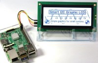
Smart I2C interface for graphic LCDs [160545]

An intelligent, platform-independent I2C interface for LCDs with KS0108 controllers
This project simplifies the use of KS0108-based monochrome graphic LCD modules. These displays have an 8-bit parallel interface and control signals that would need at least 14 port pins of your host system, but this interface allows you to use just two I2C lines plus an additional buffer flag line to display text and graphics. But most important: this intelligent interface offers a complete set of text and graphic commands to control the display and six character fonts of different heights and widths, freeing your host system from time-consuming graphic operations and critical timing issues.
There are many displays with KS0108 controllers, we divided the most common versions (yes: there are more!) into three types: Type 1 (128 x 64 pixels) and Type 2 (4”, 64 x 192 pixels) with square pixels and Type 3 (3.3” 192 x 64 pixels) with rectangular pixels. Every type has its own pin arrangement on the interface connector and also the location of the connector on the displays differs. The third type is less suited for graphic applications due to its non-isometric pixels: squares will look like rectangles on these displays and circles will become ovals. The PCB for this project is designed for Type 1 and Type 2: it has two connectors (one for either type) and a jumper that switches the firmware to the correct resolution at power on.
BOM 160545-1 V1.1
Resistor
R1,R6 = 10 kΩ, carbon film, 5%, 0.25W, 250V
R2 = 3.3 kΩ, carbon film, 5%, 0.25W, 250V
R3,R4 = 4.7 kΩ, carbon film, 5%, 0.25W, 250V
R5 = 22 Ω, carbon film, 5%, 0.25W, 250V
P1 = 10 kΩ, trimmer,20%, 0.15W, vertical
Capacitor
C1,C2,C4,C5 = 100 nF, 50 V, X7R, 5.08 mm pitch
C3,C6 = 100µF, 25V, 20%, pitch 2.54mm
Semiconductor
T1 = BC547C, 45 V, 100 mA, 500 mW, hfe=400
T2 = BC636, -45 V, -800 mA, 1 W, hfe=25
IC1 = 8-bit Microcontroller ATMega328-PU EPS 160545-41
IC2 = LP2950-33LPRE3, LDO, 3.3 V, 100mA
Other
K1 = Pin header, breakable, 1 row, 8-way, horizontal
LCD1,LCD2 = LCD KS-0108 192x64/128x64 pixels *
LCD1,LCD2 = 20-way Board-To-Board Connector, 2.54 mm, D01-9922046*
LCD1,LCD2 = SIP wire wrap socket, breakable, 20-way, vertical *
Misc.
PCB 160545-1 V1.1
* = see text


Discussion (0 comments)