

Softstart unit for amplifier
This project includes a softstart circuit for powering up an audio-amplifier and some peripherie.
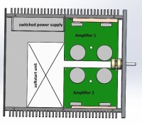
Some month ago I planned to build an amplifier. The amplifier should be built as small as possible. So I decided to use a 300W switched power supply to drive the amplifier. Because of the inrush current of the supply, a softstart unit was needed.
My research at the internet revealed, that there is no unit which would fulfill my needs.
So I decided to develop it by myself.
The concept of this unit is based on the ATTINY24 microcontroller which programmed statemachine will start first the main power supply and after that the amplifiers. This sequence is necessary, because the big capacitor of the amplifier (>50mF) will cause the supply in short circuit mode.
For a comfortable use, there is a remote control ability achieved by the µC. Via IR interface a servo motor of the volume pot could be controlled. Of course, I designed an automatically starting trigger of the amplifier, if there is any audio signal on the line inputs. Also an additional supply for the preamp is included on the PCB.
So thank you for reading this and be sure that constructive criticism is always welcome...
Discussion (4 comments)

F1Andy 7 years ago
Good project! I have a question though - why did you use opto isolators to drive the relay coils, and not just simple transistors?
Andy
Andy
Reply


Hans Gans 7 years ago
I use the double opto relay (TLP222 is bidirectional) for the motor drived volume poti because I must reverse the current polarity of the motor. The motor is supplied from an aux +/- voltage of the SMPS and it is galvanic separated. So this seems to me the easist and a place-saving solution.
The reason for the other opto relay is the galvanic separation from the DC amplifier supply. The power for the relay (ca. 60mA) could not be supplied additionally from the standby 12V because it is only a poor 1,5VA transformer a means of energy saving in standby.
Thanks for your comment!
The reason for the other opto relay is the galvanic separation from the DC amplifier supply. The power for the relay (ca. 60mA) could not be supplied additionally from the standby 12V because it is only a poor 1,5VA transformer a means of energy saving in standby.
Thanks for your comment!
Reply
Show more
2 Comment(s)
vidalv 7 years ago
Please could you add a correct path to download the UC code ? THanks !
Reply
Hans Gans 7 years ago
I must apologize for the lack of uploaded software in the last months, but unfortunately the software is not finished yet. As soon as the software is ready and tested I´ll upload the project complete. It constists near the amplifier, the softstarter for the SMPS also of an 2.5 way analog crossover with balanced input
The embedded code is necessary for the µC which controls the start up sequence of the SMPS and the IR volume control.
The embedded code is necessary for the µC which controls the start up sequence of the SMPS and the IR volume control.
Reply
Show more
3 Comment(s)


Updates from the author
Hans Gans 5 years ago
The attached sketch shows how the Softstart Unit must be connected correctly to the controlling audio source. It should be noted that the different ground lines are not connected due to the galvanic isolation. Correctly, the shielding should only be applied at one end.
If there is no need for the auto "ON / OFF" function, it can be switched off. You will find this point after the last IR Teach command using the power button, which switches between active or inactive "Auto ON / OFF".
Hans Gans 5 years ago
So I upload the actually version here.
ElektorLabs 5 years ago
Hans Gans 5 years ago
Die Klemme K11_1 sollte von L* in N* umbenannt werden. Die Klemme K11 ist der Schaltkontakt für das SMPS bzw. den Trafo.