

Switched 7805 Replacement (120212.1)
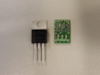
A small PCB the size of a TO-220 case containing a PWM voltage regulator to replace the classic 7805 by a more efficient regulator and with better ripple suppression.
A small PCB the size of a TO-220 case containing a PWM voltage regulator to replace the classic 7805 by a more efficient regulator and with better ripple suppression.
Update
I took over the project and made a PCB which uses a TPS62150 buck convertor to convert a positive potential between 5.5V and 17V to an output of 5V at 1A. If other resistor values are chosen in the feedback loop one can make a version that outputs a different potential. Like 3.3V, 2.5V, 1.8V, 1.5V or 1.2V. I haven't checked the lower voltage input limit of those lower voltages. But I guess it's about 0.5V above the output voltage at 1A output current.
The design still contains R3, for LC filter stability, which might be removed for the final version, if proven to be unnecessary.
Update 1
I managed to assemble it by hand with a hot air solder gun and solder paste. I only had to resolder the IC once, too much paste. And it functions! I just need to do some extensive tests to measure the exact performance.
Update 2
I added some test results in a zip file, I tested it with resistive loads, 4.7Ω, 20Ω and 470Ω. (Uncooled!) And I varied the input voltages to see what the effect is on the efficiency, as that is the major issue with linear regulators.
Update 3
I updated the Excel sheet with some measurents I did in the lab on an 7805. (Cooled!) I put the efficiencies together in the graphs so the difference in efficiency is obvious to see. It is also interresting to take a look at the ouput voltages, the 7805 has a way higher dropout voltage.
Update 4
I did a pulsed load test to see what would happen in an unideal load condition. I attached a 47Ω load and in parrallel a 6.8Ω load switched by an IRF530 N-MOSFET at 50kHz. That is a load step from about 10% to 85%. I am very pleased with the scope images I added here. No instability whatsoever but there is a spike when the load drops from 85% to 10%, but look at the scale, that is a frequency in the MHz range. A ferrite bead in series with the output could easily fix this. But then again, this is no realistic load scenario. I did have 1uF electrolitic caps on the input and output. A small value ceramic cap could be benificial as well.
See also [nodepicker==node/2245==Switched%207905%20Replacement%20(120212)==Switched%207905%20Replacement].
Discussion (5 comments)
efrs 11 years ago
In a recent project I've used a '7805' with the following specification:
input 100-220 V. AC
output 5V.DC 1A.
It's a simple battery charger for mobile phone. No need for power transformer, rectifier, filter capacitor....
It cost less than 3 euros.
I obtained also a 5V+-0.25V 2A for less than 10 euros.
Tuxscreen 11 years ago
Have a look at http://www.murata-ps.com/data/meters/dms-78xxsr.pdf
I use them for my 7805 replacements.
BR
Marc
nlohr 11 years ago
A possible smaller 78L05 replacemant with SOT23-chip.
With layout and assembly...
Geets,
Norbert
lm2841-300ma-42v-step-down-regulator-sch.jpg (32kb)
lm2841-300ma-42v-step-down-regulator-pcb.jpg (28kb)
All files (incl Eagle-Layout, etc.) (59kb)
nlohr 12 years ago
nigelmercier 11 years ago
Hubert 12 years ago
TymenYel 11 years ago
Here are three ICs to convert to 5 volt. Look in the datasheet and create a adaptor PCB. Components are available at conrad.com or farnell.com. I guess that you can find more DC/DC converters.
LT1776 0.4A 7.4--40V
LT1176 0.8A 10--35V
L4978 2A 8--55V
Greatings, Martijn
Raymond_Vermeulen 12 years ago