Upgrade Magic Eye EM84 to Windows10

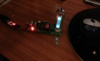
This Elektor-project from 2010 uses an EM84 magic eye to display the cpu usage of a pc. Great, but it doesn't work any more under Windows 10 :-(
This Elektor-project from 2010 uses an EM84 magic eye vacuum tube to display the cpu usage of a pc. It is based on an Atmel ATTINY2313 which also handles the USB protocol. On the pc side, AVR309.dll is the driver that is supposed to do the trick. Unfortunately, this driver does not work anymore under Windows 10 (and maybe also not under 7 or 8, I haven’t tried).
At first I tried to get the driver working under Windows 10, but in vain. After two weeks of trying I gave up, and resorted to another solution. The solution I chose is to use a separate chip to implement the USB protocol and to use serial communication on TTL-level between the USB chip and the ATTINY. An FT232 from FTDI will do the trick or you can buy cheap USB-to TTL break out boards from ebay or aliexpress.
Updates from the author
cvdo 8 years ago
cvdo 8 years ago
1. The ATTINY runs at about 3.3V, which is the primary purpose of the LED (it causes a voltage drop). The USB-to-TTL sends out signals at 5V. This is bad design. Solution: either run the ATTINY on 5V (I think the original reason was that the USB signals are specified at 3.3V). Or use a FT232R and tie its VCCIO to 3V3OUT.
2. A USB device is only allowed to pull 500mA after it has negotiated that it may do so with the host. Solution: The FT232R can do this and can give a signal CBUS3=LOW which means that 500mA has been negotiated. Or wait until you receive a command from the host.
3. A USB device may only consume 2.5mA on USB suspend. Solution: stand by when you no longer receive commands from the host. Or use the FT232R CBUS3.
4. Redesign the pcb, include FT232R, use the 12MHz output of the FT232R, ditch the XTAL as well as C6, C7, R1, D1, run at 5V, use cheaper MOSFETS.
5. Redesign the pc software, give it a nice GUI.
6. Distribute the pc software in proper form.
I have included a word document containing a complete report, including all photos and more.
cvdo 8 years ago
OK, I've got it running on my pc, but it seems that making it a piece of distributable software takes a bit more. I havent done this before and I don't intend to make it my line of work.
Here's what I did.
I downloaded and installed Visual Studio Community 2015. I studied the original software, modified it and got it running. I created a console application.
The software is only 150 lines of c++ code and consists of:
Main()... calls OpenComPort() and then goes into an infinite loop. Each 100 ms, it calls cpuusage(), which returns a value between 0 and 100%. Itdoes a calculation to convert the cpu usage in a value suitable for sending to the firmware (0..255). That value is converted to hex and then sent to the com port.
OpenComPort() first gets a list of all com ports (SerialPort::GetPortNames()) and then tries each one. It sends the string "+12" to the com port and then reads back the result. If the result is "+12!" (with an added exclamation mark), it knows it has found the correct com port. That's all there is. The source (plus some project files) is in the attachment.
I built it and it works. Can someone help me make a distributable piece of software from it, please?
cvdo 8 years ago
cvdo 8 years ago
The original code was written in assembly because it had to do all the usb stuff which has very exact timing requirements. When you remove all the usb-related code, not much is left. Therefore, I decided to re-write everything in c, in which I am more experienced. I have also moved the slow-start feature (which slowly turns on the filament power, in order to remain within the maximum 500mA usb power consumption) from the pc software to the firmware. After the slow start, the firmware does a self-test (move the display up and down a few times) and then starts to listen to the serial input. As soon as it receives two hex ascii characters in sequence (00-FF), it uses that to set the magic eye. The lower the number, the more millimetres of light. The firmware also echoes each received character and sends an exclamation mark (!) when two digits have been received.
The firmware was compiled using Atmel Studio 6.2 and the hex file is named CPUShow10.hex.
The fuse settings are: lfuse=0xff and hfuse=0xdd
I use the following commands:
avrdude -c usbasp -p t2313 -U flash:w:CPUshow10.hex
avrdude -c usbasp -p t2313 -U lfuse:w:0xff:m
avrdude -c usbasp -p t2313 -U hfuse:w:0xdd:m
Connect the usb-to-ttl board to a pc or to a 5v wall adapter and after approximately 15 seconds the EM84 should light up and move up and down a few times.
tuecok 8 years ago
But now I've Just some trouble with dll's, ucrtbase.dll and vcruntime140d.dll, they are both in System32 and TestCPU folder, but the exe-file doesn't recognize them...And what is a about COM-Port Number, is it managed by exe-file ?
cvdo 8 years ago
As for the dlls that you mention:
I found both ucrtbase.dll and vcruntime140d.dll in two places: C:\Windows\SysWOW64 and C:\Windows\System32.
On wy wife's windows 8.1 64 bit laptop, also I get the error message about vcruntime140d.dll.
According to https://www.reddit.com/r/Python/comments/3o5nhr/the_program_cant_start_because_vcruntime140ddll/
" That DLL is the Visual C++ 2015 debug runtime. You don't normally link against the debug version of the runtime for things you're going to distribute, because that version is not on end user systems. Whoever built this component did something wrong. You might be able to fix it by installing the VC++ 2015 runtime redistributable, but I wouldn't count on it. (Note that you'll need to match the bitness with whatever bitness of whatever thing you tried to install.) "
:-))) just to confirm that whoever built this component (me) didn't know what he was doing. I''ll try to fix this after the weekend, or somebody will have to help with this bit.
About the COM port stuff. As soon as you plug in the USB/TTL thing (and when the Windows drivers are loaded, which should go automatically), a new virtual COM port (e.g. COM23:) should appear in windows' Device Manager. What my software does is try all COM-ports until it finds one that responds as expected.
cvdo 8 years ago
cvdo 8 years ago
cvdo 8 years ago
The hardest part as far is hardware is concerned, is the transformer. Although I had never done it before, I had no problems because the instructions in the original article are very clear and precise. I used EFD20-3F3/K from Ferroxcube with CSH-EFD20-8P coilformer and clip CLI-EFD20. Also the choice of IRLU014 logic level MOSFETs is crucial, I found out.
Hardware changes
You need a small USB-to-TTL board, such as the one shown here on the right, that you can buy for apoproximately €1.00 from eBay or Aliexpress or for $15 from Sparkfun.
You can remove (or do not install) the usb connector and R1 from the Elektor board. If you wish to use the usb connector for whatever reason, at least remove R1.
Install four short (4cm) wires on the elector board:
- A black wire to ground (e.g. the metal of the usb connector)
- A red wire (+5V) to pin 4 of the usb connector (the trace that goes to the LED)
- A green wire on pin 2 of the ATTINY2313
- A blue wire on pin 3 of the ATTINY2313
Connect the wires to the USB-to-TTL board as follows. The order of the wires on your board may be different from the photo below!