

Virtual Fireplace [130274]
Fireplace simulator with realistic light and sound effects.
I designed a device that can simulate very well a fireplace. It needs 120V light bulbs (or anything that is dimmable). We can use one set of red lights, to create a deep-red background (not dimmed), plus one set of yellow and white lights (or anything else you like) that will be flickering according to the fire-cracking noise. In fact the device comes with a small (but loud) amplifier that plays the sound of an actual fireplace (downloaded from youtube: there are tons of them), and the yellow and white lights will flicker in unison with it.
110VAC/220VAC versions:
Virtual Fireplace
Virtueel Haardvuur
Virtueller Kamin
Feu de cheminée virtuel
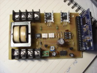
The audio file is stored in a memory card and played by means of a mp3 module TENDA TDB380. All these goods are managed by a tiny Microchip 12F683 (8pin) and two triacs. The red lights are connected straight to the mains, the yellow and white lights are driven by their respective triacs. A LM386 drives a 8 Ohm loudspeaker (approx. 500mW). There is a trimmer to adjust the volume.
The board fits also the transformer, so nothing else is needed. For your convenience, here is a video.
The firmware has been written using mikroC free edition (it's less thank 2k: actually 208 words).
IMPORTANT: suited for North America's grid (120V, 60Hz). DO NOT use anywhere else, since the timings won't work correctly.
Discussion (3 comments)
ClemensValens 11 years ago
We have been informed that the published PCB V1.1 has safety issues around the opto-couplers. We have corrected these problems and hereby present you our new design V1.2.
Sorry for the incovenience caused.
Regards,
Clemens
Eagle 6.5.0 files (94kb)
TimUiterwijk 11 years ago
Adapted the schematic and software to 230V 50Hz.
Choosen a different audio module that is more commonly available.
Build and tested a first prototype. Slight changes in the schematic due to different audio module.
Currently drawing the new schematic and PCB in Eagle.
TimUiterwijk 11 years ago
petrus bitbyter 11 years ago
The circuit can easily be adapted for 230V/50Hz. You'll have to get a 230V mains transformer of course, 230V lamps and better take an 800V version of the BT138. Also replace the 100R (R6 and R10) by 220R ones.
As for the timing I suppose the current timing was found by experimenting. You may do so for 50Hz but that can be disappointing. If you want to keep the circuit and timing (almost) unchanged, build a 120Hz pulse oscillator that produces pulses of a 50-100us. You can take transistors, a 555 or even a PIC for it.
If you like to go for a PIC, the smallest one will do. But you can also go for using the TMR1 of the PIC12F683 that is currently not used. So instead of the Interrupt On Change you have to use the TMR1 interrupt. This will of course require some changes in the software but the impact on the timing wil be minimal.
petrus bitbyter