Wireless Quiz Buttons [150499-I]

My wife is a teacher. She needed a system to run the games she organizes in class. These games are question-and-answer quizzes; the system had to be easy to use, reliable and wireless.
I chose NRF24L01+ modules for the wireless connection, which are cheap, easily available and interfaced with Atmel microcontrollers. These modules can handle up to six channels and advanced-communication mode.
In the project three channels in basic mode have been used. Each transmitter sends simply a string (“RED”, “GREEN”, “BLUE”) to the receiver, which actives one of the three outputs turning on the related color (of a RGB led strip). After having pressed a button the other ones remain disabled, until the receiver is resetted by putting a hand near the IR proximity sensor (this creates a very impressive effect, kind of a magic show ;)).
The transmitters are supplied by a 3V-coin battery (CR2032). To obtain the maximum duration of the battery the ATtiny85 is normally kept in power down mode; pressing the switch button a reset pulse is generated. The micro controller then wakes up, sends the string and returns in his power down mode.
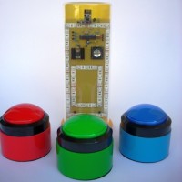
The transmitters’ boxes are big colored rolls of adhesive tape; the receiver one is a spaghetti box (I’m Italian).
The code has been written using Arduino IDE 1.6.5 and the RF24 Library. Surviving several challenging games the system can be declared successfully tested!
I'll attach some pictures, schematics, sketches and firmware of the project.
Best regards, Anto
Kit with the PCBs, programmed controllers and wireless modules available at the Elektor shop.
Discussion (3 comments)
Lucky 9 years ago
Assembling the PCBs will not be too difficult, only through-hole components are used.
On our PCBs we used connectors/sockets to mount the 2.4Ghz modules on the boards. If you feel confident enough can also solder their 8-pin headers directly to the PCB, but they may block some of the PCB's mounting holes if you do so.
The receiver board only has one component (IR LED) mounted on the bottom side. The transmitter board has the optional 6-pin ISP-connector (only needed when you want to (re)program the ATTINYs on-board) and the CR2032 battery holder on the bottom side. The latter must be placed AFTER all the other parts are soldered, you can't reach most of the solder pads when this holder is mounted.
For the LED-strips every 12V RGB type will do, but note that there are two different kinds available. Most of them have three (or six) RGB LEDs (three colours in all LEDs) mounted per section of the strip, others have discrete red, green and blue LEDs in every section. Both types can be used in this project, just something to be aware of when you order it.
Lucky 9 years ago
The schematics are almost identical to the original design of the author, with a few minor exceptions for the receiver PCB:
1. added diode D1 for input voltage polarity protection
2. changed the pinning of the UART connector K2 to standard 5V FTDI cable pinning
On the transmitter boards we added an optional 6-pin ISP-connector to allow the user to (re)program the ATTINY85 processor.
The prototype worked fine after the footprints of the BS170s were corrected :-(
The 'reset' of the receiver is a reflection sensor, consisting of an IR LED and 38kHz IR receiver. The LED is mounted on the bottom side of the PCB facing the side of the board, the receiver is on the top side and points in the same direction. It’s important to shield the receiver from the IR-LED ‘s side emission, to avoid false reset. For that reason the IR LED is placed in a short black plastic tube , a piece of black heat shrink tube will do fine too. Note that the LED only emits an unmodulated 38kHz carrier, the reset will only work if this beam is 'modulated' by moving/waving your hand.
One 'strange' effect in the software though. Arduino's 'Tone(pin,pitch,duration)' doesn't do what it should, i.e. apparently the duration parameter is omitted. That's why it's followed by a 'delay' and 'noTone' to produce a two seconds tone which normally shouldn't be necessary. Apparently one of the libraries messes with this function.
PCB layout of the transmitters (36kb)
dscn45361.JPG (1894kb)
PCB layout of the receiver (93kb)
150499-1-schematic-1.jpg (115kb)
ref.jpg (67kb)
ClemensValens 9 years ago
What are these enormous pushbuttons? Did you buy those (where?) or did you make them yourself?
Regards,
Clemens
Lucky 9 years ago
anto 9 years ago
hoteloskar 9 years ago
anto 9 years ago