

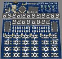
XProg Calculator v2
Cheap calculator that can convert Dec/Hex/Bin (32bits).
Welcome !
I wanted to build a very cheap calculator that can convert Dec/Hex/Bin (32bits) for my own use, and also for testing the integrated "EasyEDA / JLCPCB / LCSC" software suite solution :)
The BOM Cost is < 30$ and can be easily lowered.
This first prototype use the "CH423S" from Nanjing Qinheng Microelectronics.
It should be able to control 16 x 7seg digits for a very low price of US$ 0.31!
The micro-controller is a STM32F4 which is totally overkill for this project but I wanted to be able to reuse this board for other projects later.
Schematics, firmware and datasheet can be found here : https://github.com/bestel74/xprog_calculator
The design is currently a work in progress and NOT TESTED.
If you are interested for building one, please be patient :)
Discussion (2 comments)

svalsesia 4 years ago
Hi! Your project is cool too! Thank you!
I've decided to go with full led for mainly two reasons:
I wanted to test these chinese CH423S chips (awesome) and I wanted something retro.
But without that, I think the next upgrade would be to go on a full OLED or LCD screen.
The 74HC165 is a cool oldschool circuit by the way, it's cool :)
I've decided to go with full led for mainly two reasons:
I wanted to test these chinese CH423S chips (awesome) and I wanted something retro.
But without that, I think the next upgrade would be to go on a full OLED or LCD screen.
The 74HC165 is a cool oldschool circuit by the way, it's cool :)
Reply

MkStevo - MkEDS 4 years ago
Old school yes, but simple to use and (better!) simple for me to understand. I have been using the 74HC595 to drive a large number of different style LED displays for work, mainly four digit, seven segment displays. The '595 is ideal for this purpose, as the processor does not need to constantly refresh the display. Once the required numerals have been sent to the display, they stay on there with no interaction from the processor required until the display needs updating. This means I can use a simpler processor (cheaper!) in my designs. I had been playing with the 74HC165 as a way of incorporating some switches on those displays, without needing more (or at least, not many more) pins on my processor. I was rather pleased that my "multiplexing" idea for all the switches on the calculator worked as well as I hoped it should.
More old school still, is my "Dekatron" inspired clock. This uses five 74HC595 to drive forty LEDs. The design is shown (once again) on the Great Cow Basic forum, and also here in my Elektor Lab: https://www.elektormagazine.com/labs/dekatron-inspired-clock
Again, thanks for sharing your design.
More old school still, is my "Dekatron" inspired clock. This uses five 74HC595 to drive forty LEDs. The design is shown (once again) on the Great Cow Basic forum, and also here in my Elektor Lab: https://www.elektormagazine.com/labs/dekatron-inspired-clock
Again, thanks for sharing your design.
Reply
Show more
1 Comment(s)
MkStevo - MkEDS 4 years ago
Hello. A neat project, thanks for sharing.
I made a similar device, but decided to use a 2x16 LCD display rather than LEDs. Mine operates in 16bit mode (showing Bin/Dec/Hex all at once) or 32bit mode where it shows only Dec and Hex. Using the LCD display massively reduced the circuit required and the only components required are a PIC processor, 74HC165 keyboard decoder, the LCD and a handful of switches.
If you find yourself curious, the source code and schematics are on the Great Cow Basic forum, under the finished projects section.
Reply
Show more
1 Attachment(s)
0 Comment(s)
Updates from the author
svalsesia 4 years ago
BOOT0 at VDD = USB DFU Bootloader.
BOOT0 at GND = The program launch.
svalsesia 4 years ago
I received the components, so now everything is on board!
And... nothing... Perfect, let's learn today!
+ The quartz was REALLY hard to solder, I did not notice that the pads does not spill over the edges!
+ µC VDDA/VREF+ was not connected to VCC in the schematic... Wait What?? >:o
+ The big pad n°4 of the LDO was not GND but VOUT
Now the µC, and I was able to program it using the SWD interface (USB DFU Bootloader does not works)
+ My debounce low pass filter was not working : long discharge problems, so I just made a software debounce and replace the capacitor with the resistor (and the resistor by a 0 ohm)
+ 2 led was inverted in the schematics (hex/dec mode)
+ Order on each 4x7 digit was inverted, it's not 4-3-2-1 but 1-2-3-4.... arf
All these problems are fixed in the V2 : New update available on github!!!
For the 2 leds that got inverted and the digit order, a software #define "FIX_V1" is available to fix them.
So, how about the CH423S?
Really cool! it's not a "real I2C" com port device = No chip address, so every "internal register" is an address (from an I2C point of view) and it does not acknowledge them.
But the the total current consumption of the board stay lower than 100mA, so the CH423S does the job.
Three level of PWM are available to control brightness. A fourth is available to disable the 20mA output current limit.
For the moment I can't get the STM32F401 to go into his USB DFU bootloader mode, and I the firmware does not works without the debugger... I have not working on this for the moment.
Bye folks!
img-20201009-161320.jpg (304kb)
img-20201009-161427.jpg (121kb)
img-20201009-161515.jpg (256kb)
img-20201009-161606.jpg (271kb)