
Zener Diode Meter
The presented solution for measuring voltage of Zener diodes using Arduino is completely new and original. The circuit uses LM317 as a constant current source and the whole measurement process is controlled by Arduino.
Introduction
There are many component testers on the market. They can test different types of semiconductors, and many passive components. However, measuring the Zener breakdown voltage is problematic due to the small voltage of the battery in the most cases.
Suggested project allow to measure diodes from 1.8V to 48V in one simple measurement. Connect diode, just click on the START button and read the value. The power of the measured diodes can be from 250mW to several Watts.
WARNING: Please be very careful. High voltage 110/220V is used in this project. If you are not familiar with the risk of touching mains voltage, please do not attempt to build the described tester.
Measurement method
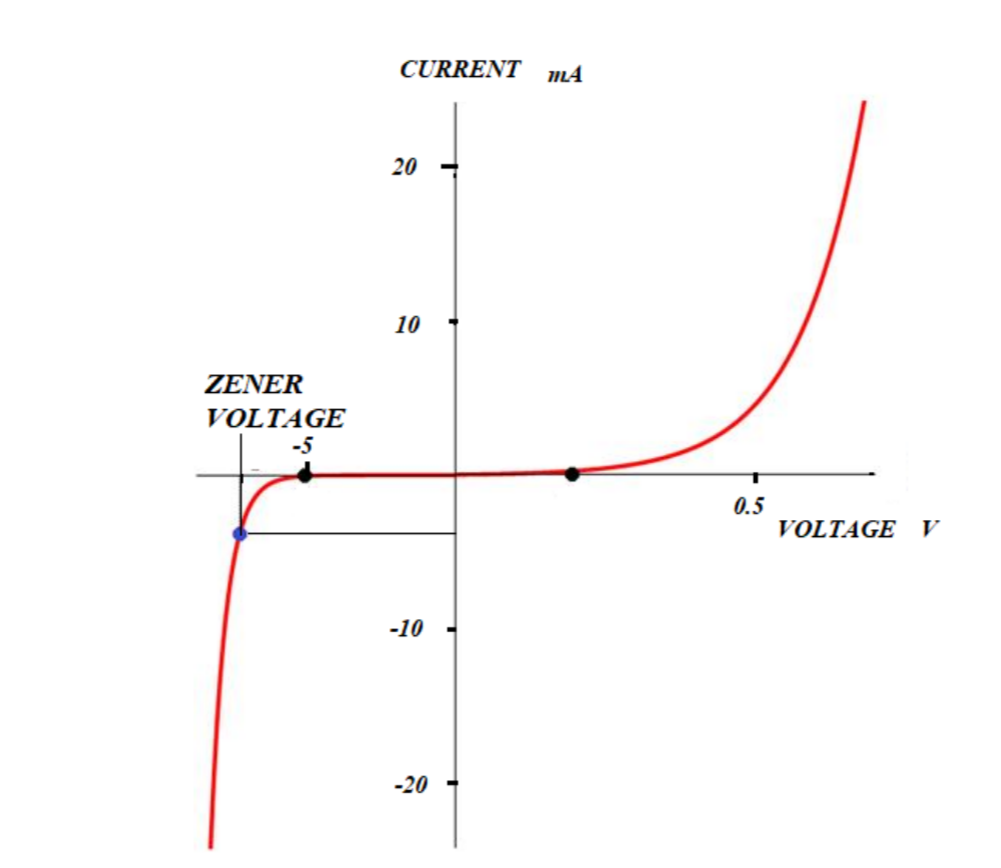
The V - I characteristic for a zener diode is shown in Figure 1. In the biased direction, a Zener diode behaves like a normal diode. In the opposite direction, at a certain voltage - Breakdown Voltage, the diode starts to conduct current. The typical voltage of a Zener diode is usually defined for a certain current - the red point in the figure. The reverse voltage is almost constant over a certain current range. As a rule, this area is also the working area of the diode.
The V - I characteristic for a zener diode is shown in Figure 1. In the biased direction, a Zener diode behaves like a normal diode. In the opposite direction, at a certain voltage - Breakdown Voltage, the diode starts to conduct current. The typical voltage of a Zener diode is usually defined for a certain current - the red point in the figure. The reverse voltage is almost constant over a certain current range. As a rule, this area is also the working area of the diode.
The tester measures this voltage at a current below the Zener knee, inside the working area. Since the selected measurement range is up to 48V, the device must be able to supply this voltage and at the same time, measure the voltage value on the diode. This happens with a constant current flow through the tested diode.
Constant current
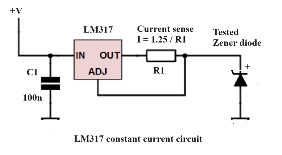
A constant current source with an LM317 voltage regulator is used as the main measuring circuit. The circuit in the following figure ensures that the current at OUT and through the diode will be constant. The current is stable, regardless of the voltage drop on the tested diode and the voltage value at the IN input. For this reason, we can measure the voltage directly on Zener diode.
Parts
- Enclosure from OKW, Shell-type OKW 9408331
- Hi-Link AC/DC adapter 220V/12V, 2pcs, eBay
- Hi-Link AC/DC adapter 220V/5V, 2pcs, eBay
- AC/DC adapter 220V/24V 150mA, eBay
- Arduino Nano
- Capacitors 100n, 2pcs, M33 1pc
- Diodes 1N4148 5pcs
- IC1, LM317T, high voltage version, eBay
- IC2, 78L12, eBay
- Transistors 2N222 5pcs
- Relay DPDT, type HK19F-DC-5V-SM6, 4pcs, AliExpress
- Reed relay, 5V, AliExpress
- Resistors 33R, 470R, 1k 4pcs, 4.7k, 10k, 15k 2pcs
- Trimm3296W 100R, 200R, 500R 2pcs, eBay
- Screw terminal block, Banggood
- Connector JST XH 2pins,
- Connector JST XH 3pins,
- Small mini main switch
- DVM 0 - 100V, 3 wire, AliExpress
- Power plug inlet, eBay
- Audio connector spring terminal
- Microswitch and button, Banggood
- LED 3mm green and red, 2pcs
- Fuse 0.5A and fuse holder 5x20mm
- Main power cord for small instruments
General description
The measurement is controlled by the Arduino Nano. Microprocessor gradually connects the range of voltages from lower to higher in four steps. At each step, it checks the current through the measured Zener diode. If it is above zero, it means that a Zener voltage has been detected. In this case, voltage will be displayed for a certain time (set by the code for 10 seconds) and the measurement will stop. If current is not present, the Arduino switches to the next step, the next voltage. MCU repeats this process until the last step.
The value of the constant current in each step is different and decreases with increasing step number of the voltage range. This will not overshoot the power dissipation of the diode.
Description of the circuit
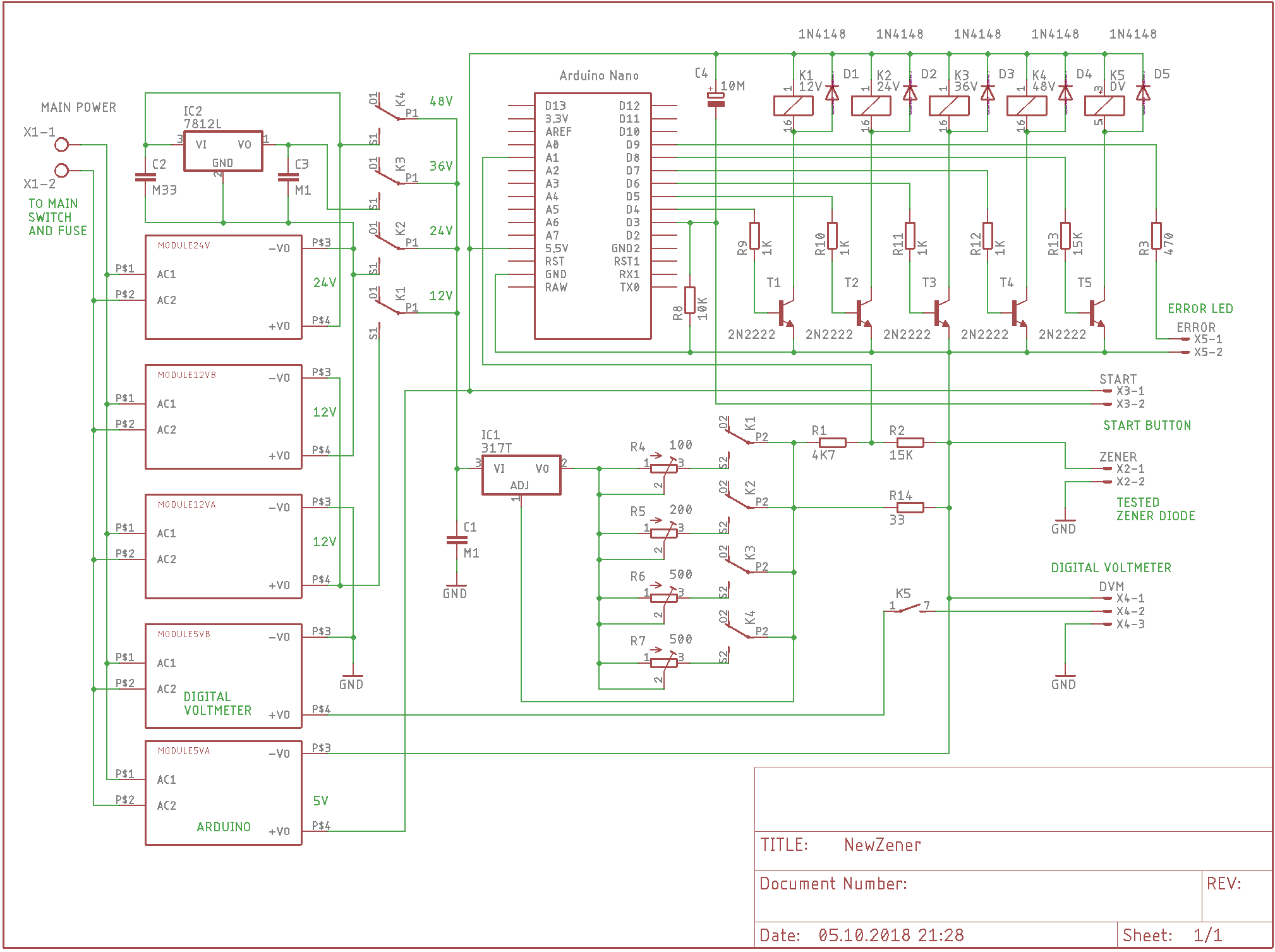
Circuit description refer to attached connection diagram:
On the left side, there is high voltage part. Terminal block for 220V connection and all five AC/DC main voltage step down modules. These power sources deliver measurement voltages in four steps - ranges: 12V, 24V, 36V, 48V.
Modules 5VA and 5VB are dedicated for MCU Arduino Nano and Digital Led Voltmeter. Modules 12VA supply the first range 12V and module 12VB add another 12V to second range value 24V. Next module 24V add another 24V to total the fourth range voltage 48V. Inside the last 24V module is 12V regulator circuit, providing 12V as the third range value to 36V. This solution was necessary because size of board does not allowed six modules to be mounted on it.
In the middle part is located IC1 LM317. IC1 must be in version for higher voltage (50V). It is connected as constant current regulator circuit and provide constant current through whole range of each voltage step. This current is stable in one range, but different in each step. The values are adjustable and are 20mA (12V), 10mA(24V), 7mA(36V), 5mA(48V). Values are chosen as upper limits for diode with 250mW power and they are good enough for more powerful diodes.
On both sides of IC1 are relays, connected the right voltage step to its input and the right trimmer resistor to its output. Trimmer resistor specifies current value on output and this current is fed to measured Zener diode via resistor R14. Current is checked on this resistor by Arduino. Voltage divider R1, R2 take reduced sample of voltage on R2 and connect it to analog pin A1.
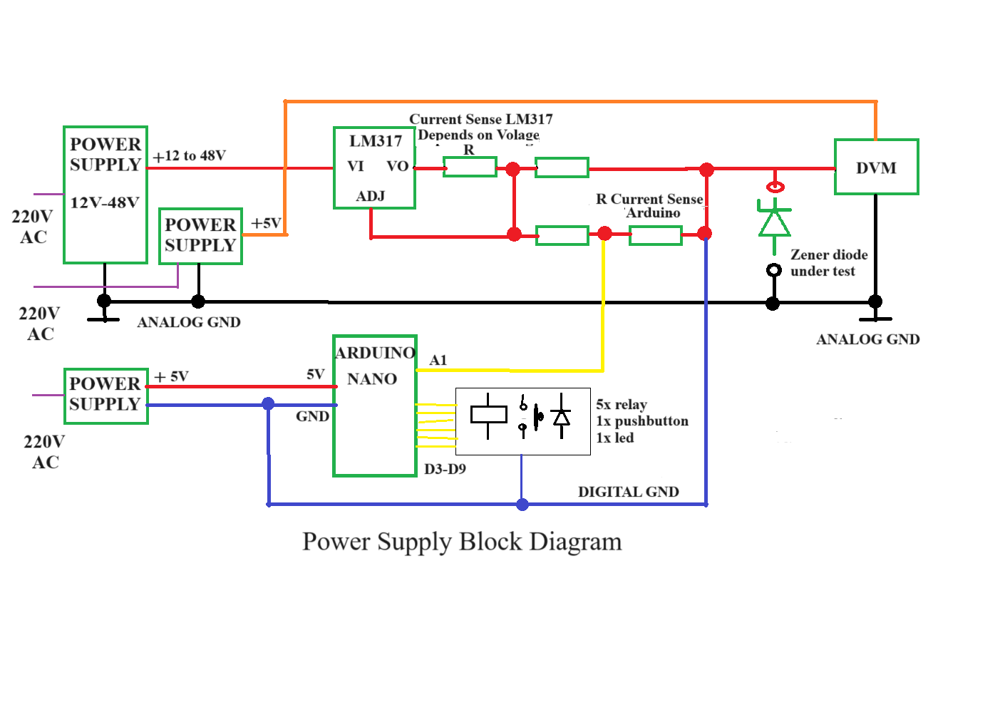
Analog ground GND is common for all voltage adapters, digital voltmeter adapter and IC1. There is another ground, digital, for Arduino and its 5V power source. Digital ground is necessary for Arduino and its analog input as measurement reference point. When constructing the tester, it is necessary to clarify the connection of analog and digital ground. For this reason, I am attaching the following picture of the block connection to the power sources. (There is more power supplies).
After I have finished project, I decided to add one more led - POWER, because if voltmeter is dark (off), there is not very clear if instrument itself is on or off. Led Power is connected in series with resistor 470 between points outside of PCB, from Start X3-1 to Zener X2-1. Resistor is mounted on small board with push button.
Construction
As a box for the project, I have used enclosure OKW, found in old electronic parts store. This box is still available at OKW as a shell type enclosure. The box is not very suitable because is too small for the board, but some upgrade of box itself and PCB allow to put all parts inside. PCB was designed in Eagle as maximum size for free version 8x10cm. In the first moment it looks like impossible to put all components on board, but finally I was successful.
Box upgrade require to remove some plastic parts inside, and stands for screws. There is necessary to modify plastic box for digital voltmeter, and make round cutout on two corners, near Error and Main power connectors. Upgrades are visible on pictures. Important thing is to make window for voltmeter as close to the box edge as possible. Push button START is located on small board and mounted with metal angle.
Windows and holes on the upper cover are made for Digital voltmeter, push button, spring terminal, LED Error, LED Power and USB Arduino Nano connector. On the lower part there is cutout for power switch and power plug inlet. Digital voltmeter and power switch are fixed on place by hot melt glue. The same way are fixed both 3mm Led diode indicators.
Measured diode is connected, not very typically, by audio spring connector. I was looking for some simple and fast connection. This solution seems to be the best one.
After soldering all components on the board, I have very carefully isolated two 220V tracks on bottom part of PCB. Wires leading from the board to power switch and to power plug inlet are isolated by heat-shrinkable tubing. Do it carefully, there should not be any exposed 220V wire or cooper track. PCB is fixed on place by adhesive rubber spacers, which prevent it from vertical moving.
On front panel there is label print on adhesive photo paper. Label is done in Paint, which is tool in Windows 10 accessories. This tool is suitable for making instrument labels, because label could be done exactly in real size.
PCB is designed by Eagle free software. I recommend to order the board at PCB service company and for this reason is attached Gerber zip. file.
Programming and setting
Programming and setting
Arduino software - ino file is attached. I try to document all main parts of code and hope it is better understandable than my English. What need to be explain from the code is function "service". It is service mode and could be used for setting instrument if you switch it for the first time.
Function for reading current "readCurrent()" was introduced to code to prevent accidental random current reading. In this function, reading is done ten times and maximal value is chosen from ten values. The maximum value of current is taken as sample to analog input of Arduino.
In service mode you adjust four adjustable resistor R4 to R7. Each trimmer is responsible for current in one voltage range. R4 for12V, R5 for 24V, R6 for 36V and R7 for 48V. In this mode mentioned voltages are gradually presented at output terminals and allow to adjust required value of current (20mA, 10mA, 7mA, 5mA).
To enter service mode press START just after switching instrument on, within 2 seconds. The first step (12V) is activated and ERROR led is blinking once. Now is time to adjust current. If current is adjusted, activate the next step(24V) by pressing START again. ERROR led is blinking twice. Repeat next steps the same way, using START button. Leave service mode by START button. In each time, the best moment for pressing START is time if led ERROR is dark after series of blinks.
Current adjustment is done by connected any Zener diode with voltage around middle range , for instance, 12V range it should be 6 to 7V diode. This Zener diode must be connected in series with ammeter or multi-meter. Adjusted value of current should not be precise, minus 15% to plus 5% is OK.
Discussion (0 comments)