Article
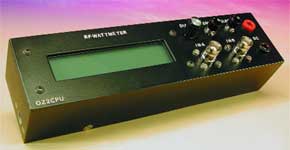
Digital RF Wattmeter with LC Display
for 1 kHz to 1 GHz

Any radio amateur knows the importance of an accurate RF power meter. A wattmeter can be used to measure gain in amplifiers, bandwidth in filters, field strength from antennas, transmitter power, SWR, return loss and many other things.This RF wattmeter uses an AD8307 to measure the power level. The AD8307 front end circuit is both frequency compensated and optimised for return loss to give optimum input SWR over a wide frequency range. A pre-programmed microcontroller type PIC16F876 with built-in 10-bit analogue to digital converters is used to convert the analogue voltage output from the AD8307 into digital values. Next, a set of lookup tables are used to convert the dBm values into RF voltage and RF power (watts).
Materials
Gerber file
CAM/CAD data for the PCB referred to in this article is available as a Gerber file. Elektor GREEN and GOLD members can exclusively download these files for free as part of their membership. Gerber files allow a PCB to be produced on an appropriate device available locally, or through an online PCB manufacturing service.
Elektor recommends the Elektor PCB Service service from its business partner Eurocircuits or AISLER as the best services for its own prototypes and volume production.
The use of our Gerber files is provided under a modified Creative Commons license. Creative Commons offers authors, scientists, educators and other creatives the freedom to handle their copyright in a more free way without losing their ownership.
PCB
Extra info / Update
Capacitor C2 is missing from the circuit diagram. It should be connected between junction C1/R6/R7 and pin 8 (INP) of IC1. The capacitor at pin 1 of IC1 should be labelled C3, not C2.
Component list
Resistors
SMD case 1206 or 0805:
R1,R2,R3 = 100? (R3 on top of R1/R2)
R4 = 39?
R5 = 33?
R6 = 68?
R7 = 47?
R8 = 470k?
R9 = 47k?
R10,R11 = 1k?
R15 = 120k?
R16 = 10k?
R17 = 180k?
R14 = 10? 1W
P1 = 10k? preset
Capacitors
SMD case 1206 or 0805:
C1 = 8pF2
C2-C7,C9,C10,C11,C14 = 100nF
C8 = 1nF
C12 = 10µF 16V radial
C13 = 100µF 25V radial
Inductor
L1 = 3 turns, 0.5mm dia. ECW (SWG #30), turns spaced at 0.5mm, internal dia. 3mm.
Semiconductors:
D1 = 1N4001
IC1 = AD8307AR (SMD)
IC2 = PIC16F876-04/SP, programmed, order code 020026-41
IC3 = 7805
Miscellaneous:
K1 = 5-way SIL pinheader
K2,K5 = 3-way SIL pinheader
K3 = 16-way SIL pinheader
K4 = BNC socket with flange
K6 = 4-way SIL pinheader
S1,S2 = pushbutton, 1 make contact, chassis mount
PC1,PC3,PC8,PC10,PC12 = solder pin
X1 = 4MHz ceramic resonator (3 pins)
LCD module with 2 lines of 20 characters, e.g., LM032L (PC2002LRS-BEA-C)
Rotary encoder type 3315Y-1-016 (Bourns)
Mains adapter socket, chassis mount
IC socket, 28 pins, narrow
PCB, order code 020026-1
Disk, source code files, order code 020026-11
SMD case 1206 or 0805:
R1,R2,R3 = 100? (R3 on top of R1/R2)
R4 = 39?
R5 = 33?
R6 = 68?
R7 = 47?
R8 = 470k?
R9 = 47k?
R10,R11 = 1k?
R15 = 120k?
R16 = 10k?
R17 = 180k?
R14 = 10? 1W
P1 = 10k? preset
Capacitors
SMD case 1206 or 0805:
C1 = 8pF2
C2-C7,C9,C10,C11,C14 = 100nF
C8 = 1nF
C12 = 10µF 16V radial
C13 = 100µF 25V radial
Inductor
L1 = 3 turns, 0.5mm dia. ECW (SWG #30), turns spaced at 0.5mm, internal dia. 3mm.
Semiconductors:
D1 = 1N4001
IC1 = AD8307AR (SMD)
IC2 = PIC16F876-04/SP, programmed, order code 020026-41
IC3 = 7805
Miscellaneous:
K1 = 5-way SIL pinheader
K2,K5 = 3-way SIL pinheader
K3 = 16-way SIL pinheader
K4 = BNC socket with flange
K6 = 4-way SIL pinheader
S1,S2 = pushbutton, 1 make contact, chassis mount
PC1,PC3,PC8,PC10,PC12 = solder pin
X1 = 4MHz ceramic resonator (3 pins)
LCD module with 2 lines of 20 characters, e.g., LM032L (PC2002LRS-BEA-C)
Rotary encoder type 3315Y-1-016 (Bourns)
Mains adapter socket, chassis mount
IC socket, 28 pins, narrow
PCB, order code 020026-1
Disk, source code files, order code 020026-11


Discussion (0 comments)