

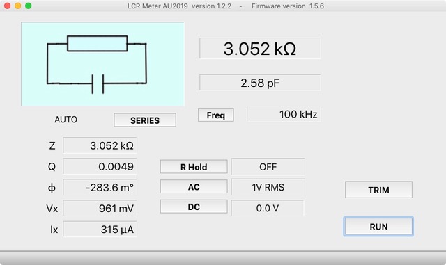
New LCR Meter 50 Hz - 2 MHz Part 1
automatic impedance measuring bridge measures the resistance, capacitance and inductance of components with an impedance of 10 mΩ to 100 MΩ
Materials
Extra info / Update
Component list
Main PCB 190311-1 V2.3
Resistors
(SMD 0603 1% 100ppm unless otherwise stated)
R1,R4,R5,R8,R20,R25,R26,R37,R66,R109,R124,R164,R188 = 1k
R2,R7,R10,R14,R22,R60,R61,R62,R63,R151,R187,R192 = 10k
R3,R35,R36,R38,R65,R71,R112,R113,R129,R135,R136,R160,R183,R184,R185 = 100k
R6,R15,R45,R47,R49,R51,R67,R82,R89,R90,R119,R122,R128,R130,R131,R137,R138,R139,R140,R141,R142,R144,R162,R165,R178 = 51Ω
R9 = 27k
R11,R171 = 2.4k
R12,R13 = 27Ω
R16 = 3.6k
R17,R172 = 1.6k
R18,R132,R133,R173 = 3k
R19,R21,R110,R115 = 2k
R23,R24,R120 = 30k
R27,R28,R29,R32 = 2k 0.1% 25ppm
R30,R80,R106,R107,R108 = 620Ω
R31 = 50Ω trimmer (Bourns 3266W)
R33,R34,R64 = 33Ω 100ppm 1206
R39,R70,R84,R126,R127 = 100Ω
R40,R41 = 110k
R42,R123 = 240Ω
R43 = 560Ω
R44,R147 = 100Ω 0.01% 50ppm 0805
R46,R148 = 1k 0.01% 10ppm 0805
R48,R149 = 10k 0.01% 10ppm 0805
R50,R150 = 100k 0.01% 10ppm 0805
R53,R55,R57,R59,R180 = 20k
R68,R125,R177,R189,R190,R191 = 510Ω
R69,R174 = 12k
R73,R88,R166,R167,R168,R169 = NC
R74 = 47k
R75,R121,R153,R161 = 10Ω
R76 = 150Ω
R77 = 91Ω
R78,R79 = 30Ω
R81 = 200Ω
R143 = 0Ω
R83 = 1.2k
R85,R95,R96,R97,R98 = 390Ω
R86 = 75Ω
R87 = 43Ω
R91,R92,R93 = 1.3k
R94 = 6.8k
R99,R116,R117,R154,R155,R159 = 4.7k
R100,R101,R102,R103,R104,R105,R118 = 3.9k
R114 = 300Ω
R134 = 2.7k
R145 = 7.5k
R146 = 10k trimmer (Vishay TS53YJ)
R152 = 47Ω
R156,R170 = 1.5k
R157 = 56k
R158 = 160k
R163 = 200k
R175,R176 = 33k
R179 = 5.1k
R181 = 51k
R182 = 75k
R186 = 120k
Inductors
L1,L2 = Bead Murata BLM21AG102SN1D
L3,L4,L5,L16 = 470nH TDK MLZ1608DR47DT
L6,L14,L15,L20 = 10µH TDK MLZ2012M100WT
L7 = 2.2µH Coilcraft 1008PS-222KLB
L8 = 22µH Cooper Bussmann DRQ73
L9 = NC
L10,L11,L12,L13,L18,L19 = 33µH TDK MLZ2012M330WT
L17 = 22µH Taiyo Yuden CBC3225T220MR
Capacitors
(0603 unless otherwise stated)
C1,C2,C3,C4,C9,C15,C16,C23,C27,C28,C29,C30,C31,C45,C46,C47,C53,C54,C55,C56,C58,C59,C60,C61,C62,C63,C65,C66,C67,C75,C79,C82,C83,C84,C92,C98,C99,C100,C101,C102,C103,C104,C107,C110,C111,C113,C118,C119,C120,C123 = 100nF 50V 10% X7R
C5,C6,C8,C19,C24,C26,C40,C41,C78,C89,C90,C91,C94,C108 = 4.7µF 10V 10% X7R 0805
C7,C11,C13,C17,C18 = 2.2µF 10V 10% X7R 0805
C10 = 270pF 50V 5% NPO
C12,C57,C64,C77, C130 = 10nF 50V 10% X7R
C14 = 470µF 6.3V EEEFP0J471AP PANASONIC (Aluminium Electrolytic)
C20,C21,C81,C95,C96,C97 = 1µF 25V 10% X7R 0805
C22 = 33µF 6.3V CASE-A (Solid Tantalum)
C25 = 1nF 50V 5% NPO 0603
C32,C34,C36,C38,C50,C93 = 1.5pF 50V 0.25pf NPO
C33,C35,C37,C39 = 3.9pF 50V 0.25pF NPO
C42,C48,C49,C105,C112,C114,C115,C116,C127,C128,C129 = NC
C43 = 180pF 50V 5% NPO
C44,C106 = 2-10pF trimmer (Knowless Voltronics JZ100)
C51 = 4.5-20pF trimmer (Knowless Voltronics JZ200)
C52 = 240pF 50V 5% NPO
C68,C69,C70,C71 = 220pF 50V 5% NPO
C72,C73,C109 = 82pF 50V 5% NPO
C74 = 47pF 50V 5% NPO
C76 = 6.8pF 50V 0.25pF NPO
C80 = 68pF 50V 5% NPO
C85,C86,C124,C125 = 100nF 50V 5% NPO 1206
C87,C88 = 15nF 50V 5% NPO 1206
C121 = 1pF 50V 0.25pF NPO 0603
C122 = 100pF 50V 5% NPO 0603
C126 = 22pF 50V 5% NPO 0603
C112, C114, C115, C116, C127, C128, C19 = NC
Semiconductors
D1,D2,D12 = red LED, low power 0805
D3,D4 = Schottky diode MBR0520
D5,D11 = diode 1N4148WS
D6,D7 = dual diode BAV199 LT1G
D8,D9,D10 = Schottky diode NSVRB751V40T1G
Q1 = P-channel MOSFET IRLML6402
Q2,Q3,Q4,Q5,Q6,Q7 = N-channel MOSFET BSS123
Q8,Q9 = RF NPN BFR106
U1 = USB6B1 ESD protection
U2 = FT232RL USB to UART
U3 = LT1946A DC/DC switching regulator
U4 = REG103GA-5 linear regulator 5V 500mA
U5 = TLV70030DDCR linear regulator 3V 200mA
U6 = LM2611AMF Buck converter
U7,U26 = LMH6644MT quad OPAMP
U9,U10,U11,U12 = AD8099ARDZ OPAMP
U19,U37 = LMH6618MK OPAMP SOT23_6
U20,U21,U22 = LMH6720MF OPAMP SOT23_6
U23 = 74HCT4052D analog multiplexer
U24,U25 = AD9834BRUZ DDS IC
U27 = OPA2727AID precision amplifier
U28,U31 = TLV3501AIDB analog comparator
U29 = 74LVC1G04DBVT inverter
U30,U66 = 74LVC1G74DCTR flip-flop
U41,U42,U46 = 74LVC1G3157DBVR analog switch
U43 = ADS1246IPW 24-bit ADC
U44 = LM4050CIM3-2.5 voltage reference 2.5V
U45,U62,U63,U64,U67,U68 = 74LV1T34DBVR buffer
U49 = 8-bit MCU C8051F120-GQ
U50,U51,U52,U53,U58,U59 = AQY221N2S Solid State relay
U54,U55,U56,U57 = AQY221R2S Solid State relay
U70 = 74HCT4051D analog multiplexer
Miscellaneous
J1 = USB_B_Mini (TE Connectivity 1734035-2)
J2,J3 = 3-way SIL 2.54mm
J4,J5,J6,J7 = BNC PCB-mount (TE Connectivity 1-1337543-0)
J8,J9,J17,J10,J11,J12,J13,J16 = 2-way-90º SIL 2.54mm
J14 = 24-way boxheader
J15 = 10-way boxheader
J20,J21,J22 = test point
K1 = Optional 6mm push button (Omron BF3-1020)
SW1 = toggle switch Nidec Copal AS1D-5M-10-Z
Y1 = 27 MHz oscillator Epson X1G0044510005 SG5032CAN 27 MHZ TJGA
PCB 190311-1 VER 2.3
Display PCB 190311-2 V2.0 & Enclosure
Resistors
(SMD 0603 unless otherwise stated)
R1 = 500k
R2 = 620k
R3,R19 = 100k
R4,R5 = 33Ω SMD 0805
R7 = 51Ω
R6,R8 = NC
R9,R11,R12,R13,R23,R24,R26 = 4.7k
R18 = 0Ω
R20 = 10k
R21 = 1M
R22,R25,R27,R28,R29,R31 = 330Ω
Capacitors
C1,C3 = 4.7uF 10V 10% X7R 0805
C4 = 1uF 25V 10% X7R 0805
C5 = 100nF 50V 10% X7R 0603
C6,C10,C11,C12,C13,C14,C16 = 220nF 50V 10% X7R 0603
C7,C8,C9 = 2.2uF 10V 10% X7R 0805
Semiconductors
D2,D3,D4,D5,D12,D13 = dual diode BAT54A SOT23
D14 = diode 1N4148WS SOD323
Q1,Q2 = N-channel digital MOSFET FDV303N SOT23
U1 = Display MCCOG240128A6W-FPTLW (MIDAS)
U2 = TLV70030DDCR linear regulator 3V 200mA SOT23-5
Miscellaneous
J1 = 24-way boxheader (i.e. T821 series Amphenol)
SW1 = Rotary encoder PEC11R-4115F-S0018 (BOURNS)
PCB 190311-2 VER 2.0
Enclosure: HAMMOND 1455N1601
4 x Standoff hex female/female M3 7 mm
1 x Standoff hex female/female M3 6 mm
1 x Flat washer steel 3 mm
5 x Machine screw, countersink head M3 16 mm
5 x Washer M3
5 x Nut M3
2 x IDC connector socket 24 contacts (AMPHENOL T81214A101CEU)
24-way flatcable 15 cm
Rotary knob aluminium (e.g. MENTOR 507.61)
4 x Jumper 2.54mm gold plated
Discussion (0 comments)
William Hall 4 years ago
William Hall 4 years ago
IK2HEW 4 years ago
all useful files in the above downloads are password protected.
Please, how it works ?
Thanks.
IK2HEW 4 years ago
Thanks a lot again.
fraubrj 4 years ago
What do you mean by password protected?
None of the files to be downloaded are password protected. They are archives (.zip) that you have to unzip to be able to use them!
IK2HEW 4 years ago
Sorry.....
Content Director, Elektor 4 years ago
Sam H Reaves 3 years ago
Sam
Content Director, Elektor 3 years ago
- 190311 AU2019 DOC EN & FR 2021-01-04.zip
- 190311 AU2019 Files & Code DOWNLOAD 2021-10-06.zip
- 190311 AU2019 BOM Gerbers PDFs Enclosure 2021-01-14.zip
- Texts LCR6 Rev 1.1.txt
Go to the page and then click the SOFTWARE tab.Content Director, Elektor 3 years ago
Sam H Reaves 3 years ago
I bought the archive of Elector magazine and found many errors in that product. I emailed a detailed document to them along with all of the needed changes, Never heard a peep from anyone at elector on that. I spent probably three days solid going through and checking every single issue to fix the problems and no one from the company even took 5 minutes to write me back and acknoledge any of the work I had done.
I just wanted to make sure that the next guy that buys the very expensive USB stick of magazines would have a clean fully usable copy without duplicates or copies with the wrong pages in the index, etc. Most of the magazines (I found out later) I could have found on the internet for free download but thought it would be more handy (and quicker) just to but the archive.
In any event on the files for this project I certainly would not hold my breath waiting for them.
Sam
W3OHM
Tako Tamas 3 years ago
Thanks,
Tamas
fraubrj 3 years ago
Download the 190311 AU2019 Files & Code DOWNLOAD 2021-10-06.zip archive, unzip it, and the programs are in the AU2019 - programs for the different platforms folder.
The last Win7-32 version is on the archive AU2019 V 1.3.4 Win7-32.zip
fraubrj 3 years ago
Therefore it is recommended to ask your questions on the home page of this project on Elektor Labs
https://www.elektormagazine.com/labs/remake-lcr-meter
Please scroll down to the Discussion area and click on the blue Add a comment button
Southerner 3 years ago
Nice2Know 3 years ago
https://www.elektormagazine.com/labs/remake-lcr-meter
Scroll down to view "Updates from the author" then click on "Show More" and scroll down to the following list of updates:
SCHEMATIC _ LCR6-Display REV 2.3.pdf (36kb)
Textes LCR6 v3.txt (9kb)
c20-modif.jpg (154kb)
190311 AU2019 Files & Code DOWNLOAD 2021-10-06.zip (94464kb)
190311 AU2019 BOM Gerbers PDFs Enclosure 2021-10-08.zip (858kb)
190311 AU2019 DOC EN & FR 2021-10-09.zip (8648kb)
AU2019 V 1.3.4 Win7-32.zip (23074kb)
kelvin-clips.jpg (70kb)
AU2019 - device programs 2021-12-10.zip (530kb)
mesures-10-kw.jpg (331kb)
th26001a-modified.jpeg (923kb)
190311 AU2019 Schematics 2021-12-16.zip (263kb)
2 MHz LCR Meter Kit AU2019 Assembly Manual_v3.3.pdf (3628kb)
fraubrj 3 years ago
Therefore it is recommended to ask your questions on the home page of this project on Elektor Labs
https://www.elektormagazine.com/labs/remake-lcr-meter
Please scroll down to the Discussion area and click on the blue Add a comment button
Tako Tamas 3 years ago
fraubrj 3 years ago
Therefore it is recommended to ask your questions on the home page of this project on Elektor Labs
https://www.elektormagazine.com/labs/remake-lcr-meter
Please scroll down to the Discussion area and click on the blue Add a comment button