Article
auto trigger

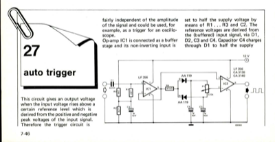
27 auto trigger This circuit gives an output voltage when the input voltage rises above a certain reference level which is derived from the positive and negative peak voltages of the input signal. Therefore the trigger circuit is fairly independent of the amplitude of the signal and could be used, for example, as a trigger for an oscillo- scope. Op-amp IC1 is connected as a buffer stage and its non-inverting input is set to half the supply voltage by means of R 1 . .. R3 and C2. The reference voltages are derived from the (buffered) input signal, via Dl, D2, C3 and C4. Capacitor C4 charges through Dl to half the supply 12 V 7-46 voltage plus the positive peak voltage of the input signal. C3 is charged through Dl and P1, but in this case diode D2 ensures that the voltage across C3 is not more than half the supply voltage minus the peak negative voltage. The values chosen in this part of the circuit are such that the reference voltages across the capacitors stay very constant when...


Discussion (0 comments)