Article
audio tester

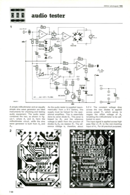
1 854231 max. 50 mV A simple millivoltmeter and an equally simple sine wave generator are ideal instruments for checking and testing audio equipment. The audio tester combines the two, as shown in fig- ure 1, where Aland A2 form the millivoltmeter circuit, while the sine wave generator is built from A3and A4. As the audio tester is supplied (asym- metrically) from a 9 V battery, this supply must be halved for the oper- ational amplifiers. This is essentially done by zener diode D7. This zener is biased by R6, and the reference voltage is taken from the junction of diodes D8-D, via resistor R7. The ref- erence voltage is, therefore, about 5.3 V. The constant voltage drop across the two diodes is applied across preset P3 which serves to negate the offset voltage of A2 (enabling the millivoltmeter to be cali- brated to zero). The input signal is applied across high pass filter Cl/R Ito the non-inverting input of A1. For all practical purposes, p R1 6 A2 05 D6 D3 D4 OMI 50,A R17 • a...


Discussion (0 comments)