Article
Joystick adaptor

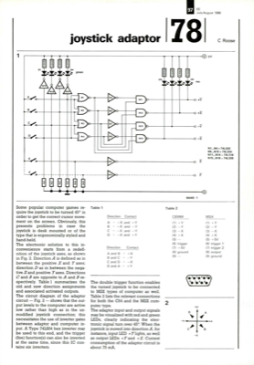
D1 N15 D5 1/11.1FNIAr INImi‚Ä¢ De joystick adaptor D4 ‚Ä¢‚Ä¢ X.7.k. green mi. N17 97 EE July/August 1986 78 C Roose 5V 44 Some popular computer games re- quire the joystick to be turned 45¬? in order to get the correct cursor move- ment on the screen. Obviously, this presents problems in case the joystick is desk mounted or of the type that is ergonomically styled and hand-held. The electronic solution to this in- convenience starts from a redefi- nition of the joystick axes, as shown in Fig. 2. Direction A is defined as in between the positive X and Y axes; direction D as in between the nega- tive X and positive Y axes. Directions C and B are opposite to A and B re- spectively. Table 1 summarizes the old and new direction assignments and associated activated outputs. The circuit diagram of the adaptor circuit - Fig. 2 - shows that the out- put levels to the computer are active low rather than high as in the un- modified joystick connection; this necessitates the use of invert...


Discussion (0 comments)