Article
Looking Back

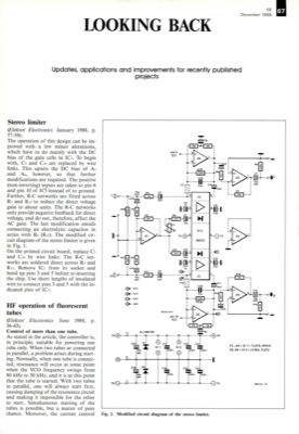
Stereo limiter (Elektor Electronics January 1988, p. 57-59). The operation of this design can be im- proved with a few minor alterations, which have to do mainly with the DC bias of the gain cells in IC3. To begin with, C3 and Cio are replaced by wire links. This upsets the DC bias of As and A6, however, so that further modifications are required. The positive (non-inverting) inputs are taken to pin 6 and pin 10 of IC), instead of to ground. Further, R-C networks are fitted across R5 and R12 to reduce the direct voltage gain to about unity. The R-C networks only provide negative feedback for direct voltage, and do not, therefore, affect the AC gain. The last modification entails connecting an electrolytic capacitor in series with R6 (R13). The modified cir- cuit diagram of the stereo limiter is given in Fig. 1. On the printed circuit board, replace C3 and Cu by wire links. The R-C net- works are soldered direct across R5 and R13. Remove IC2 from its socket and bend up pins 3 and 5...


Discussion (0 comments)