Article
2-metre band converter
capture 144 MHz DX signals
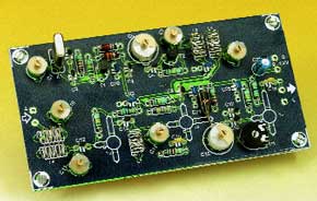
If you have a general coverage shortwave receiver available and would like to extend its frequency range with the two-metre amateur radio band, the present design is for you. Easy to build from low-cost parts, the converter should make an excellent entry-level project for budding radio enthusiasts. The converter is also a prefect companion to the general-coverage multi-mode SW receiver described last year in this magazine.The 2-metre radio amateur band is still the most popular band worldwide. It extends from 144 to 146 MHz in most European countries, and from 144 to 148 MHz is some other countries like the U.S.A. and Australia. Traditionally, the band is associated with short-range communication over distances of up to 50 miles or so using narrow-band frequency modulation (NBFM) and power levels up to about 50 watts. This is also called ‘local traffic’ by some radio amateurs. Thanks to the relatively short antenna lengths and general profusion of cheap Japanese hightech rigs and converted PMR kit, the 2-m band is also the place to be for mobile and portable communication, witness the presence of amateur-built and operated repeater stations in many countries and areas.
Materials
Gerber file
CAM/CAD data for the PCB referred to in this article is available as a Gerber file. Elektor GREEN and GOLD members can exclusively download these files for free as part of their membership. Gerber files allow a PCB to be produced on an appropriate device available locally, or through an online PCB manufacturing service.
Elektor recommends the Elektor PCB Service service from its business partner Eurocircuits or AISLER as the best services for its own prototypes and volume production.
The use of our Gerber files is provided under a modified Creative Commons license. Creative Commons offers authors, scientists, educators and other creatives the freedom to handle their copyright in a more free way without losing their ownership.
PCB
Component list
Resistors:
R1,R4,R10 = 150k?
R2,R9 = 2k?2
R3 = 180k?
R5 = 560?
R6 = 47k?
R7 = 100k?
R8 = 1k?
R11 = 56?
P1 = 1k? preset H
Capacitors:
C1,C7,C8,C10,C11,C14 = 22pF trimmer
C2 = 27pF
C3,C6,C9,C12,C18 = 10pF
C4 = 15pF
C5,C16 = 40pF trimmer
C13 = 4pF7
C15,C19 = 1nF, raster 5mm
C17 = 22pF
C20,C22-C25 = 100nF ceramic
C21 = 10µF 63V radial
Inductors:
L1 = 0.22µH miniature choke
L2 = 0.33µH miniature choke
L3-L7 = 5 turns silver-plated wire, dia. 0.8mm (SWG20), internal diameter 4.5mm, length 10mm Distance between coupled inductors: 1mm, tap at 2 turns from ground side
L8 = 0.56µH miniature choke
Semiconductors:
T1,T2 = BF494
T3,T5 = BFR91
T4 = BF961
Miscellaneous:
X1 = quartz crystal 38.667MHz (3rd overtone) (Mainline, tel. 0870 2410810)
PCB, order code 000013-1
Case: e.g. Hammond 1590B 56×107×25 (inside dimensions)
Discussion (0 comments)