Article
Midget medium-wave receiver
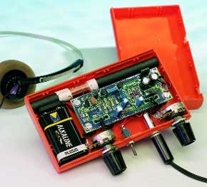
The tiny medium-wave (MW) receiver described in this article is an ideal construction project to while away the dreariness of a rainy winter’s day. Solder a couple of standard components onto a tiny printed-circuit board, connect the finished board to a battery, and Bob ’s your uncle. Nowadays there are few construction projects or, indeed, commercially available equipment, that use discrete components only. Most apparatus encountered today has at least a processor and/or a number of integrated circuits. Although such equipment has the great advantages of reliability and simplicity, some readers may find the present project in which they can potter about without running into great difficulties a welcome surprise.The midget radio receiver consists of five common-or-garden transistors, one inductor and a handful of standard passive components. Most readers may well find that they have all the necessary components to hand.
Materials
Gerber file
CAM/CAD data for the PCB referred to in this article is available as a Gerber file. Elektor GREEN and GOLD members can exclusively download these files for free as part of their membership. Gerber files allow a PCB to be produced on an appropriate device available locally, or through an online PCB manufacturing service.
Elektor recommends the Elektor PCB Service service from its business partner Eurocircuits or AISLER as the best services for its own prototypes and volume production.
The use of our Gerber files is provided under a modified Creative Commons license. Creative Commons offers authors, scientists, educators and other creatives the freedom to handle their copyright in a more free way without losing their ownership.
PCB
Component list
Resistors:
R1 = 1M?
R2 = 1k?5
R3,R7 = 1k?8
R4 = 2M?2
R5 = 10k?
R6 = 560k?
R8 = 220?
R9 = 5k?6
P1 = 50k? linear potentiometer
P2 = 50k? logarithmic potentiometer
Capacitors:
C1 = 470pF
C2,C3,C4,C7 = 10nF
C5,C6 = 1µF 16V radial
C8,C9 = 220µF 16V radial
C10 = 100µF 63V radial
C11 = 100nF
Inductor:
L1 = 50 turns 0.3mm dia. (SWG30) enamelled copper wire on ferrite rod (10x100mm)
Semiconductors:
D1 = BB509 *
D2,D3 = 1N4148
T1 = BF245C or BF256C
T2,T3 = BC550C
T4 = BD140
T5 = BD139
Miscellaneous:
K1 = 3.5 mm jack socket
S1 = on/off switch
Bt1 = 9-V battery with clip-on connector
Ls1 = earpiece, headphones or 8? loudspeaker Enclosure: e.g., Conrad Electronics 52 09 93 (123x30x70mm)
PCB, order code 000034-1
Discussion (0 comments)